52a MITSUBISHI LANCER 2005 User Guide
[x] Cancel search | Manufacturer: MITSUBISHI, Model Year: 2005, Model line: LANCER, Model: MITSUBISHI LANCER 2005Pages: 788, PDF Size: 45.98 MB
Page 300 of 788
WINDOW GLASS
BODY42-22
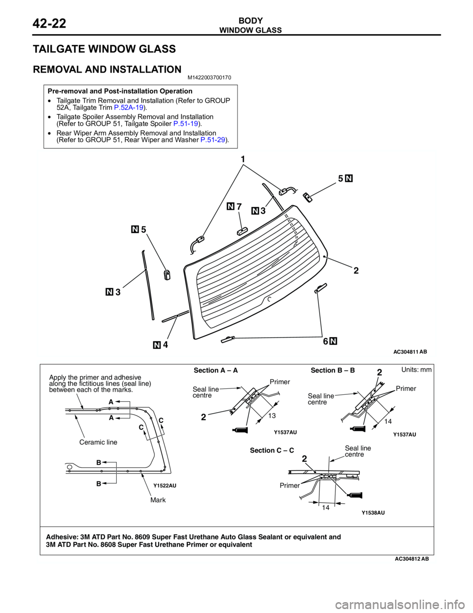
TAILGATE WINDOW GLASS
REMOVAL AND INSTALLATIONM1422003700170
Pre-removal and Post-installation Operation
•Tailgate Trim Removal and Installation (Refer to GROUP
52A, Tailgate Trim P.52A-19).
•Tailgate Spoiler Assembly Removal and Installation
(Refer to GROUP 51, Tailgate Spoiler P.51-19).
•Rear Wiper Arm Assembly Removal and Installation
(Refer to GROUP 51, Rear Wiper and Washer P.51-29).
AC304811
1
2
6 55
4 33 7
AB
N
NN
N
N
N
N
Y1522AU
Y1538AU
AC304812
Y1537AUY1537AU
AB
Units: mm
Adhesive: 3M ATD Part No. 8609 Super Fast Urethane Auto Glass Sealant or equivalent and
3M ATD Part No. 8608 Super Fast Urethane Primer or equivalentSection A – A
13
14
14 Section B – B
Section C – C A
A
CC
B
B Ceramic line
Mark Apply the primer and adhesive
along the fictitious lines (seal line)
between each of the marks.
Seal line
centrePrimer
Seal line
centrePrimer
Seal line
centre
Primer
22
2
Page 306 of 788
DOOR
BODY42-28
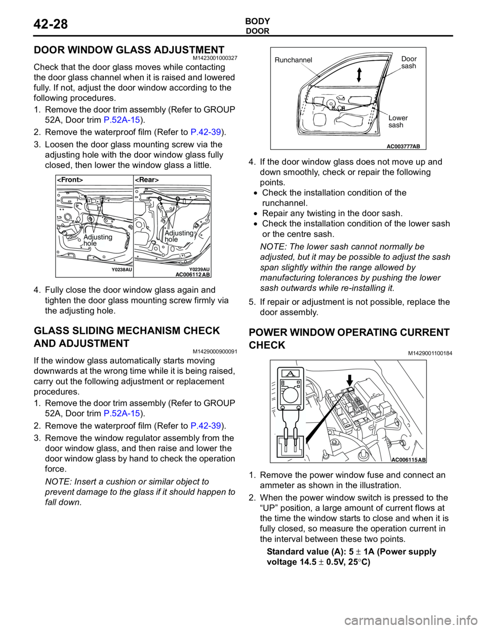
DOOR WINDOW GLASS ADJUSTMENTM1423001000327
Check that the door glass moves while contacting
the door glass channel when it is raised and lowered
fully. If not, adjust the door window according to the
following procedures.
1. Remove the door trim assembly (Refer to GROUP
52A, Door trim P.52A-15).
2. Remove the waterproof film (Refer to P.42-39).
3. Loosen the door glass mounting screw via the
adjusting hole with the door window glass fully
closed, then lower the window glass a little.
4. Fully close the door window glass again and
tighten the door glass mounting screw firmly via
the adjusting hole.
GLASS SLIDING MECHANISM CHECK
AND ADJUSTMENT
M1429000900091
If the window glass automatically starts moving
downwards at the wrong time while it is being raised,
carry out the following adjustment or replacement
procedures.
1. Remove the door trim assembly (Refer to GROUP
52A, Door trim P.52A-15).
2. Remove the waterproof film (Refer to P.42-39).
3. Remove the window regulator assembly from the
door window glass, and then raise and lower the
door window glass by hand to check the operation
force.
NOTE: Insert a cushion or similar object to
prevent damage to the glass if it should happen to
fall down.4. If the door window glass does not move up and
down smoothly, check or repair the following
points.
•Check the installation condition of the
runchannel.
•Repair any twisting in the door sash.
•Check the installation condition of the lower sash
or the centre sash.
NOTE: The lower sash cannot normally be
adjusted, but it may be possible to adjust the sash
span slightly within the range allowed by
manufacturing tolerances by pushing the lower
sash outwards while re-installing it.
5. If repair or adjustment is not possible, replace the
door assembly.
POWER WINDOW OPERATING CURRENT
CHECK
M1429001100184
1. Remove the power window fuse and connect an
ammeter as shown in the illustration.
2. When the power window switch is pressed to the
“UP” position, a large amount of current flows at
the time the window starts to close and when it is
fully closed, so measure the operation current in
the interval between these two points.
Standard value (A): 5 ± 1A (Power supply
voltage 14.5 ± 0.5V, 25°C)
Y0238AUY0239AUAC006112
AB
Adjusting
holeAdjusting
hole
AC003777
RunchannelDoor
sash
Lower
sash
AB
AC006115AB
Page 308 of 788
DOOR
BODY42-30
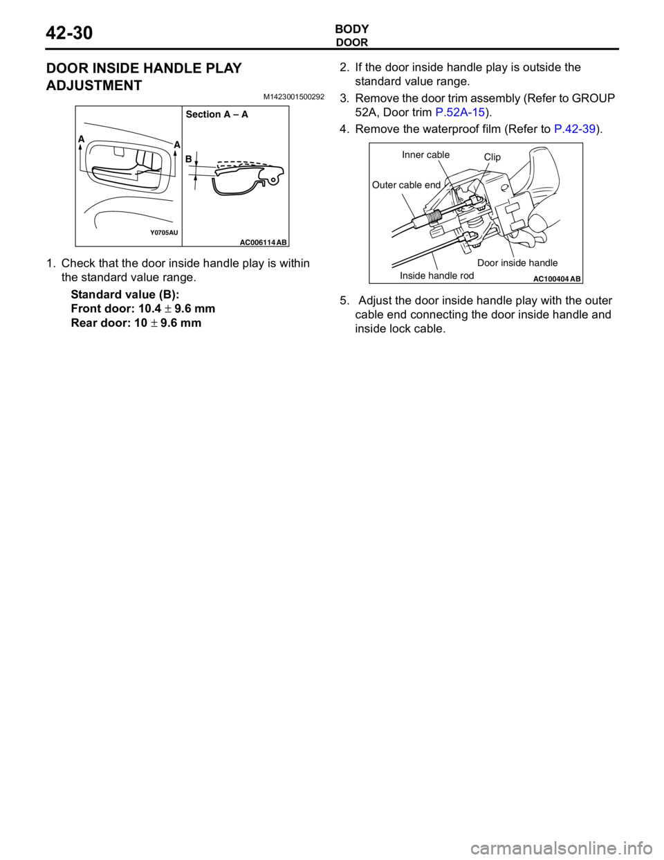
DOOR INSIDE HANDLE PLAY
ADJUSTMENT
M1423001500292
1. Check that the door inside handle play is within
the standard value range.
Standard value (B):
Front door: 10.4 ± 9.6 mm
Rear door: 10 ± 9.6 mm2. If the door inside handle play is outside the
standard value range.
3. Remove the door trim assembly (Refer to GROUP
52A, Door trim P.52A-15).
4. Remove the waterproof film (Refer to P.42-39).
5. Adjust the door inside handle play with the outer
cable end connecting the door inside handle and
inside lock cable.
AC006114Y0705AUAB
A
A
BSection A – A
AC100404
AB
Clip Inner cable
Outer cable end
Inside handle rodDoor inside handle
Page 309 of 788
DOOR
BODY42-31
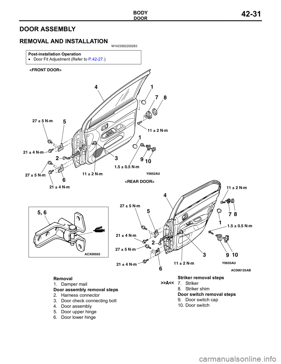
DOOR ASSEMBLY
REMOVAL AND INSTALLATIONM1423002200283
Post-installation Operation
•Door Fit Adjustment (Refer to P.42-27.)
Y0655AU
AC006125
ACX00503
Y0652AU
5, 6
AB
1
2
3 4
5
678
910 1
234
5
67
8
9
10 11.5 ± 0.5 N·m 1.5 ± 0.5 N·m
11 ± 2 N·m11 ± 2 N·m
11 ± 2 N·m
11 ± 2 N·m 21 ± 4 N·m 27 ± 5 N·m 21 ± 4 N·m 27 ± 5 N·m
21 ± 4 N·m 27 ± 5 N·m
21 ± 4 N·m 27 ± 5 N·m
Removal
1. Damper mail
Door assembly removal steps
2. Harness connector
3. Door check connecting bolt
4. Door assembly
5. Door upper hinge
6. Door lower hingeStriker removal steps>>A<<7. Striker
8. Striker shim
Door switch removal steps
9. Door switch cap
10. Door switch
Page 311 of 788
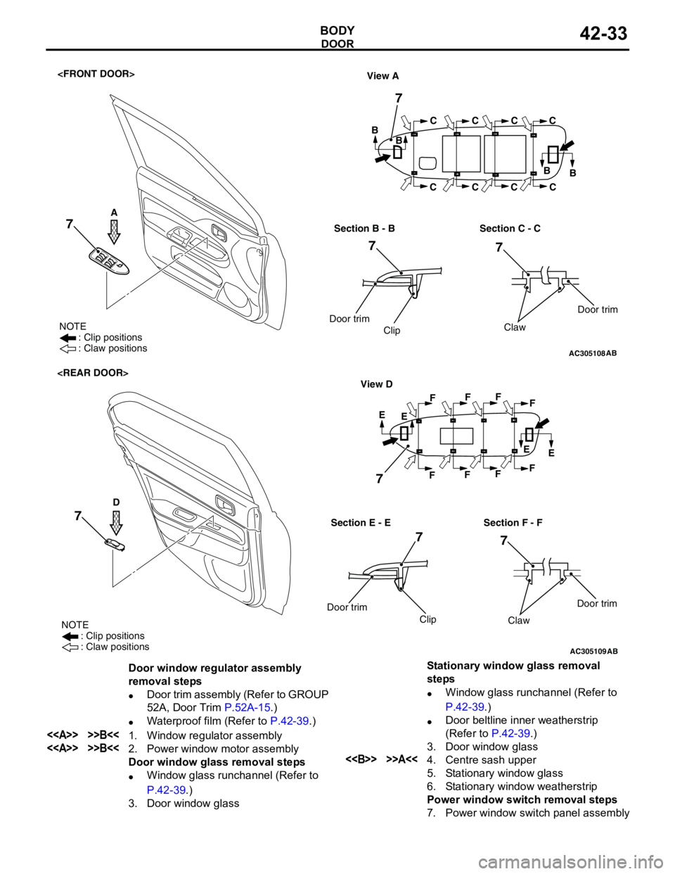
DOOR
BODY42-33
AC305108
NOTE
: Clip positions
: Claw positions
View A
B
B
B
B C
CC
CC
CC
C
Section B - B
Door trim
ClipSection C - C
AB
Door trim
Claw
7
7
7 7
A
AC305109
NOTE
: Clip positions
: Claw positions
E
E
E
E F
FF
FF
FF
F
Section E - EView D
Door trim
ClipSection F - F
Door trim
Claw
D
7
7 7
AB
7
Door window regulator assembly
removal steps
•Door trim assembly (Refer to GROUP
52A, Door Trim P.52A-15.)
•Waterproof film (Refer to P.42-39.)
<> >>B<<1. Window regulator assembly
<> >>B<<2. Power window motor assembly
Door window glass removal steps
•Window glass runchannel (Refer to
P.42-39.)
3. Door window glassStationary window glass removal
steps
•Window glass runchannel (Refer to
P.42-39.)
•Door beltline inner weatherstrip
(Refer to P.42-39.)
3. Door window glass<> >>A<<4. Centre sash upper
5. Stationary window glass
6. Stationary window weatherstrip
Power window switch removal steps
7. Power window switch panel assembly
Page 314 of 788
DOOR
BODY42-36
DOOR HANDLE AND LATCH
REMOVAL AND INSTALLATIONM1423004600328
Pre-removal Operation
•Door Trim Removal (Refer to GROUP 52A, Door trim
P.52A-15.)Post-installation Operation
•Door Inside Handle Play Check (Refer to P.42-30.)
•Door Outside Handle Play Check (Refer to P.42-29.)
•Door Trim Installation (Refer to GROUP 52A, Door trim
P.52A-15.)
AC305110
5
5.0 ± 1.0 N·m
1
4
9
2
AB
45 2
3
87
5.0 ± 1.0 N·m
1 6
9
NN
89.0 ± 2.0 N·m9.0 ± 2.0 N·m
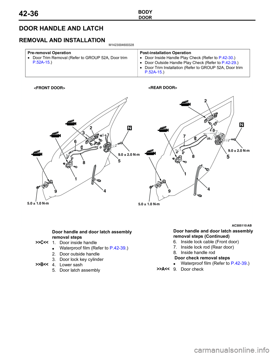
Door handle and door latch assembly
removal steps
>>C<<1. Door inside handle
•Waterproof film (Refer to P.42-39.)
2. Door outside handle
3. Door lock key cylinder
>>B<<4. Lower sash
5. Door latch assembly6. Inside lock cable (Front door)
7. Inside lock rod (Rear door)
8. Inside handle rod
Door check removal steps
•Waterproof film (Refer to P.42-39.)>>A<<9. Door check Door handle and door latch assembly
removal steps (Continued)
Page 317 of 788
DOOR
BODY42-39
WINDOW GLASS RUNCHANNEL AND
DOOR OPENING WEATHERSTRIP
REMOVAL AND INSTALLATIONM1423003100290
AC304409AB
Section A – A
Sealant: 3M ATD Part No.8633 or equivalentDoor
: Sectional view of
clip position
: Sectional view of
clip position
6 2
1
4
365
A A
1
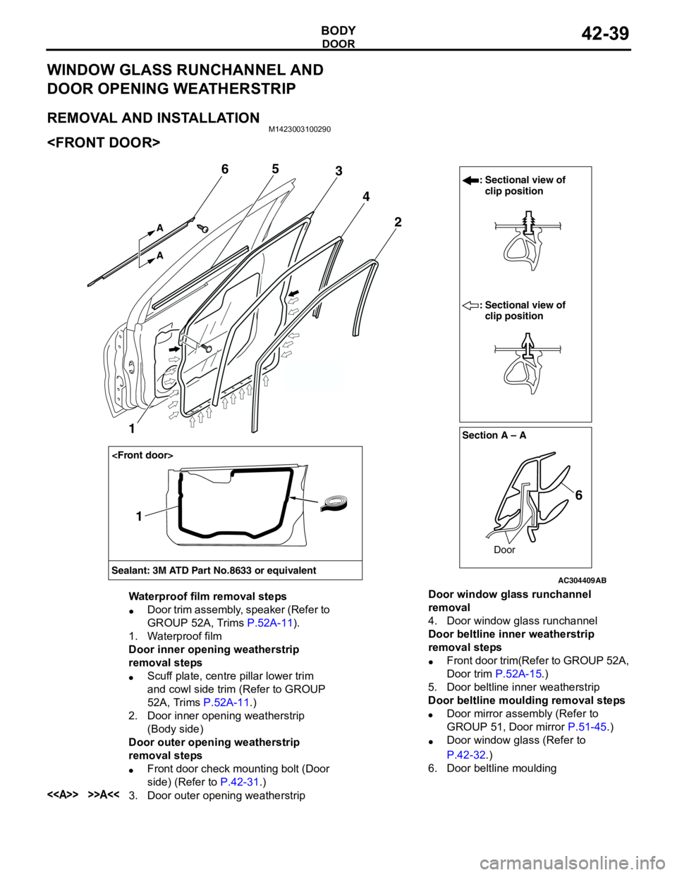
Waterproof film removal steps
•Door trim assembly, speaker (Refer to
GROUP 52A, Trims P.52A-11).
1. Waterproof film
Door inner opening weatherstrip
removal steps
•Scuff plate, centre pillar lower trim
and cowl side trim (Refer to GROUP
52A, Trims P.52A-11.)
2. Door inner opening weatherstrip
(Body side)
Door outer opening weatherstrip
removal steps
•Front door check mounting bolt (Door
side) (Refer to P.42-31.)
<> >>A<<3. Door outer opening weatherstripDoor window glass runchannel
removal
4. Door window glass runchannel
Door beltline inner weatherstrip
removal steps
•Front door trim(Refer to GROUP 52A,
Door trim P.52A-15.)
5. Door beltline inner weatherstrip
Door beltline moulding removal steps
•Door mirror assembly (Refer to
GROUP 51, Door mirror P.51-45.)
•Door window glass (Refer to
P.42-32.)
6. Door beltline moulding
Page 318 of 788
DOOR
BODY42-40
AC304418AB
Section A – A
Door
: Sectional view of
clip position
: Sectional view of
clip position
6 2 4
5
7
A A
3
Section B – B
Door
6
3
6
BB
Sealant: 3M ATD Part No.8633 or equivalent
1
1
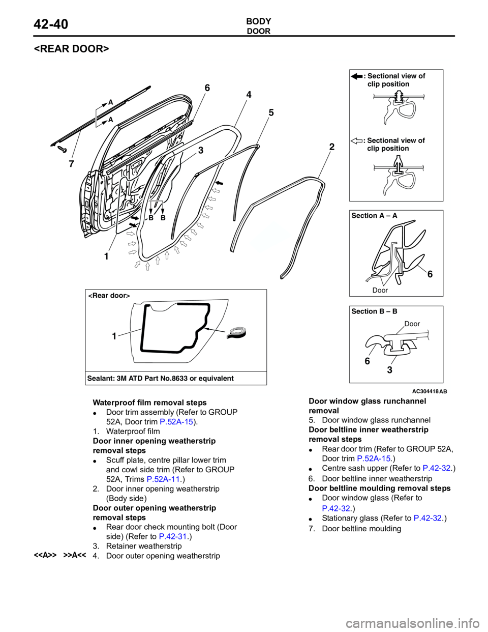
Waterproof film removal steps
•Door trim assembly (Refer to GROUP
52A, Door trim P.52A-15).
1. Waterproof film
Door inner opening weatherstrip
removal steps
•Scuff plate, centre pillar lower trim
and cowl side trim (Refer to GROUP
52A, Trims P.52A-11.)
2. Door inner opening weatherstrip
(Body side)
Door outer opening weatherstrip
removal steps
•Rear door check mounting bolt (Door
side) (Refer to P.42-31.)
3. Retainer weatherstrip
<> >>A<<4. Door outer opening weatherstripDoor window glass runchannel
removal
5. Door window glass runchannel
Door beltline inner weatherstrip
removal steps
•Rear door trim (Refer to GROUP 52A,
Door trim P.52A-15.)
•Centre sash upper (Refer to P.42-32.)
6. Door beltline inner weatherstrip
Door beltline moulding removal steps
•Door window glass (Refer to
P.42-32.)
•Stationary glass (Refer to P.42-32.)
7. Door beltline moulding
Page 321 of 788
TRUNK LID
BODY42-43
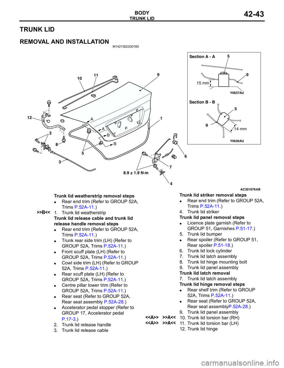
TRUNK LID
REMOVAL AND INSTALLATIONM1421002200180
AC301676
Y0636AU
Y0637AU
AB
1
2
3
45
5
6
7 89
10
99
11
12
8.9 ± 1.9 N·m A
A
B
B15 mm
14 mm
5Section A - A
Section B - B
Trunk lid weatherstrip removal steps
•Rear end trim (Refer to GROUP 52A,
Trims P.52A-11.)
>>B<<1. Trunk lid weatherstrip
Trunk lid release cable and trunk lid
release handle removal steps
•Rear end trim (Refer to GROUP 52A,
Trims P.52A-11.)
•Trunk rear side trim (LH) (Refer to
GROUP 52A, Trims P.52A-11.)
•Front scuff plate (LH) (Refer to
GROUP 52A, Trims P.52A-11.)
•Cowl side trim (LH) (Refer to GROUP
52A, Trims P.52A-11.)
•Rear scuff plate (LH) (Refer to
GROUP 52A, Trims P.52A-11.)
•Centre pillar lower trim (Refer to
GROUP 52A, Trims P.52A-11.)
•Rear seat (Refer to GROUP 52A,
Rear seat assembly P.52A-28.)
•Accelerator pedal stopper (Refer to
GROUP 17, Accelerator pedal
P.17-3.)
2. Trunk lid release handle
3. Trunk lid release cableTrunk lid striker removal steps
•Rear end trim (Refer to GROUP 52A,
Trims P.52A-11.)
4. Trunk lid striker
Trunk lid panel removal steps
•Licence plate garnish (Refer to
GROUP 51, Garnishes P.51-17.)
5. Trunk lid bumper
•Rear spoiler (Refer to GROUP 51,
Rear spoiler P.51-18.)
6. Trunk lid lock cylinder
7. Trunk lid latch assembly
8. Trunk lid hinge mounting bolt
9. Trunk lid panel assembly
Trunk lid latch removal
7. Trunk lid latch assembly
Trunk lid hinge removal steps
•Rear shelf trim (Refer to GROUP
52A, Trims P.52A-11.)
•Rear seat (Refer to GROUP 52A,
Rear seat assemblyP.52A-28.)
9. Trunk lid panel assembly
<> >>A<<10. Trunk lid torsion bar (RH)
<> >>A<<11. Trunk lid torsion bar (LH)
12. Trunk lid hinge
Page 325 of 788
TA I L G AT E
BODY42-47
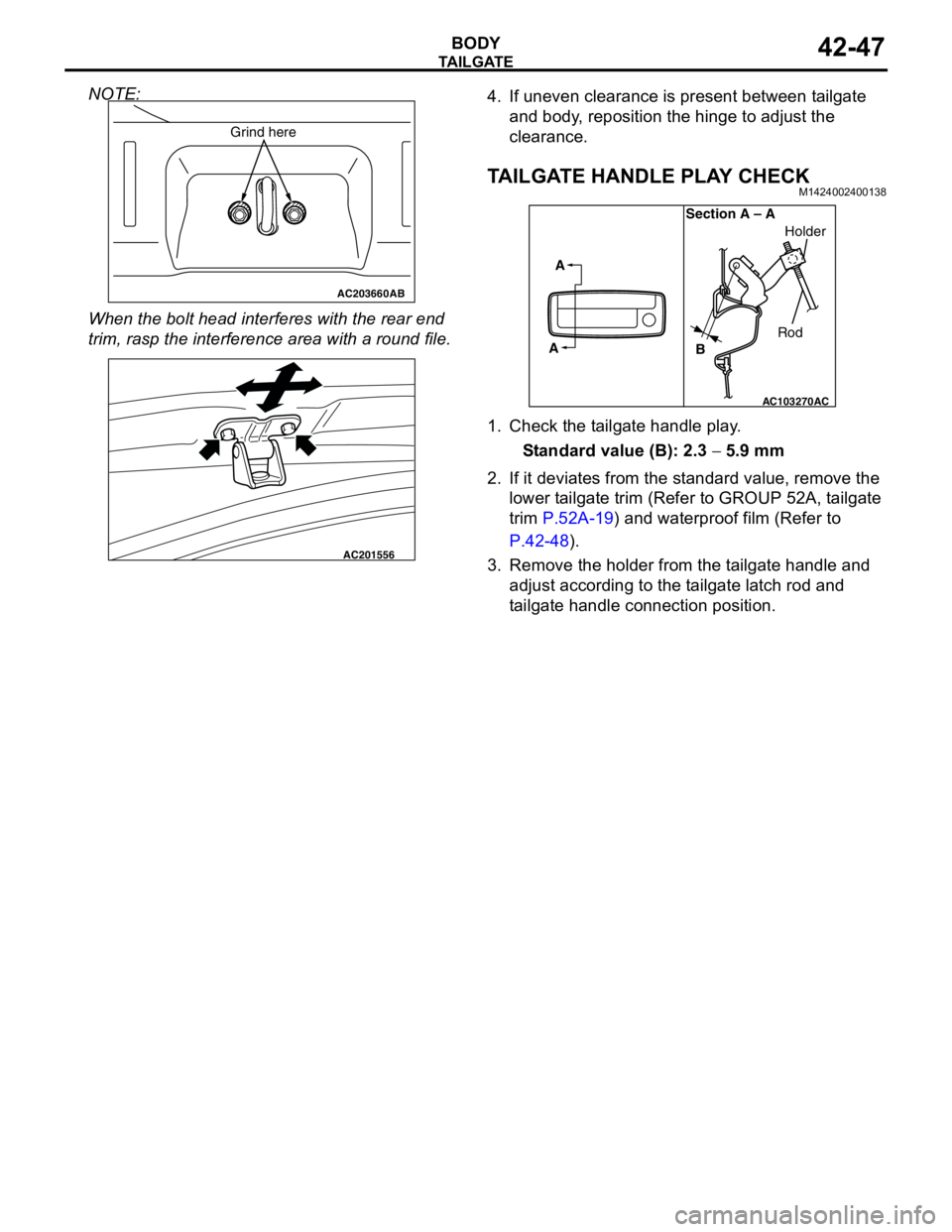
NOTE:
When the bolt head interferes with the rear end
trim, rasp the interference area with a round file.4. If uneven clearance is present between tailgate
and body, reposition the hinge to adjust the
clearance.
TAILGATE HANDLE PLAY CHECKM1424002400138
1. Check the tailgate handle play.
Standard value (B): 2.3 − 5.9 mm
2. If it deviates from the standard value, remove the
lower tailgate trim (Refer to GROUP 52A, tailgate
trim P.52A-19) and waterproof film (Refer to
P.42-48).
3. Remove the holder from the tailgate handle and
adjust according to the tailgate latch rod and
tailgate handle connection position.
AC203660AB
Grind here
AC201556
AC103270
A
ASection A – A
RodHolder
B
AC