52a MITSUBISHI LANCER 2005 Owner's Guide
[x] Cancel search | Manufacturer: MITSUBISHI, Model Year: 2005, Model line: LANCER, Model: MITSUBISHI LANCER 2005Pages: 788, PDF Size: 45.98 MB
Page 471 of 788
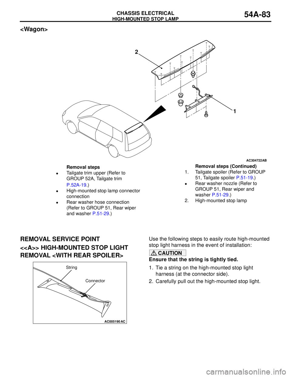
Page 481 of 788
SPEAKER
CHASSIS ELECTRICAL54A-93
SPEAKER
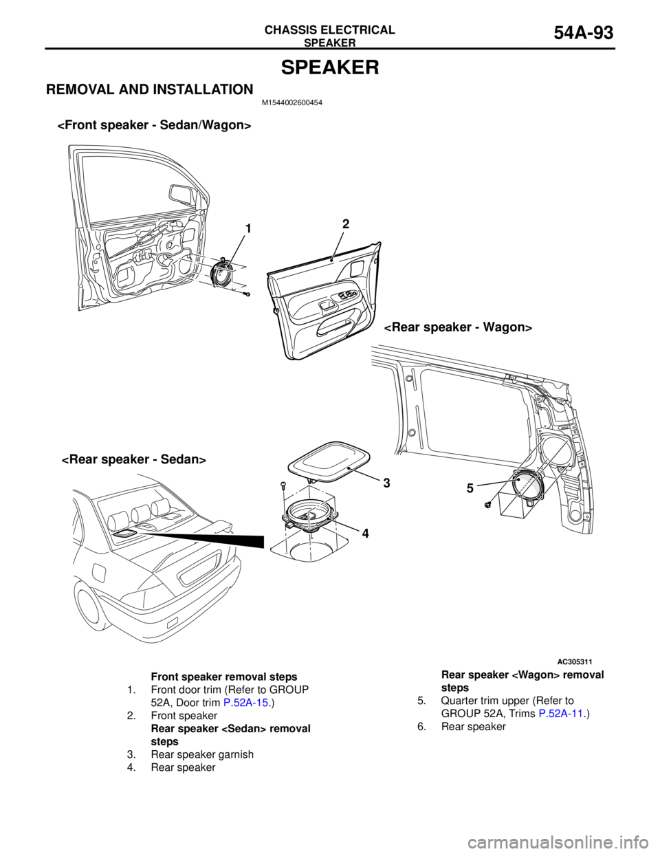
REMOVAL AND INSTALLATIONM1544002600454
AC305311AB
12
3
4
Front speaker removal steps
1. Front door trim (Refer to GROUP
52A, Door trim P.52A-15.)
2. Front speaker
Rear speaker
steps
3. Rear speaker garnish
4. Rear speakerRear speaker
steps
5. Quarter trim upper (Refer to
GROUP 52A, Trims P.52A-11.)
6. Rear speaker
Page 482 of 788
ANTENNA
CHASSIS ELECTRICAL54A-94
ANTENNA
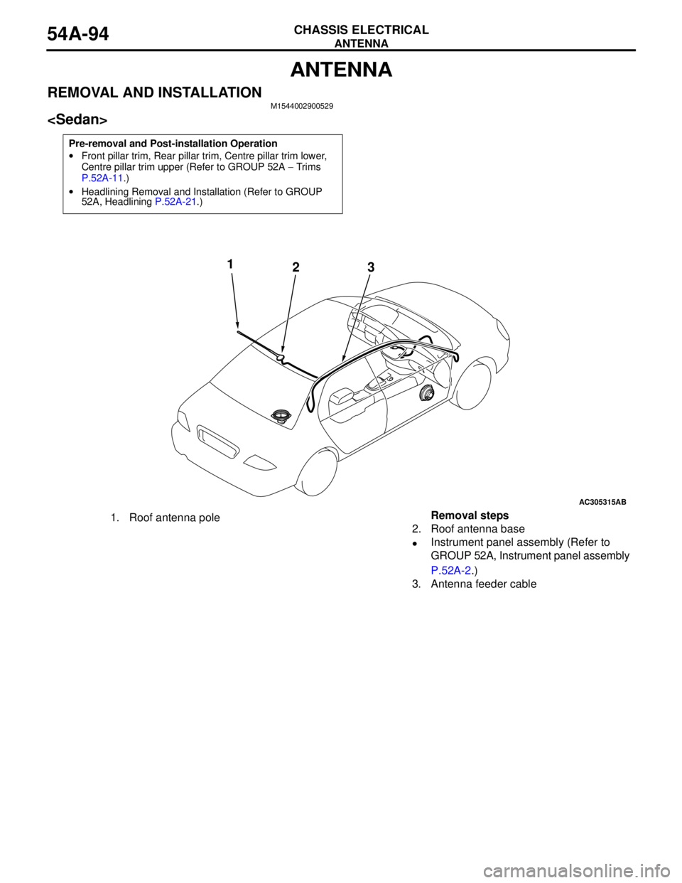
REMOVAL AND INSTALLATIONM1544002900529
Pre-removal and Post-installation Operation
•Front pillar trim, Rear pillar trim, Centre pillar trim lower,
Centre pillar trim upper (Refer to GROUP 52A − Trims
P.52A-11.)
•Headlining Removal and Installation (Refer to GROUP
52A, Headlining P.52A-21.)
AC305315AB
1
23
1. Roof antenna poleRemoval steps
2. Roof antenna base
•Instrument panel assembly (Refer to
GROUP 52A, Instrument panel assembly
P.52A-2.)
3. Antenna feeder cable
Page 483 of 788
REAR WINDOW DEFOGGER
CHASSIS ELECTRICAL54A-95
REAR WINDOW DEFOGGER
GENERAL INFORMATIONM1543000100319
Rear Defogger operation
The defogger relay turns ON if the defogger switch
built-in the A/C-ECU is turned ON when the ignition
switch is in the "ON" position. When the defogger
relay turns ON, power is supplied to the defogger
and the defogger is activated. The defogger comes
with a timer function that causes the defogger switch
to automatically turn OFF in about 11 minutes after
the defogger switch is turned ON.
TROUBLESHOOTINGM1543000701013
The rear window defogger is controlled by the
A/C-ECU. For troubleshooting, refer to GROUP 55-
Troubleshooting P.55-5.
Pre-removal and Post-installation Operation
•Front pillar trim, Centre pillar trim lower, Centre pillar trim
upper, Quarter trim lower, Quarter trim upper (Refer to
GROUP 52A − Trims P.52A-11.)
•Headlining Removal and Installation (Refer to GROUP
52A, Headlining P.52A-21.)
AC305316
AB
1
23
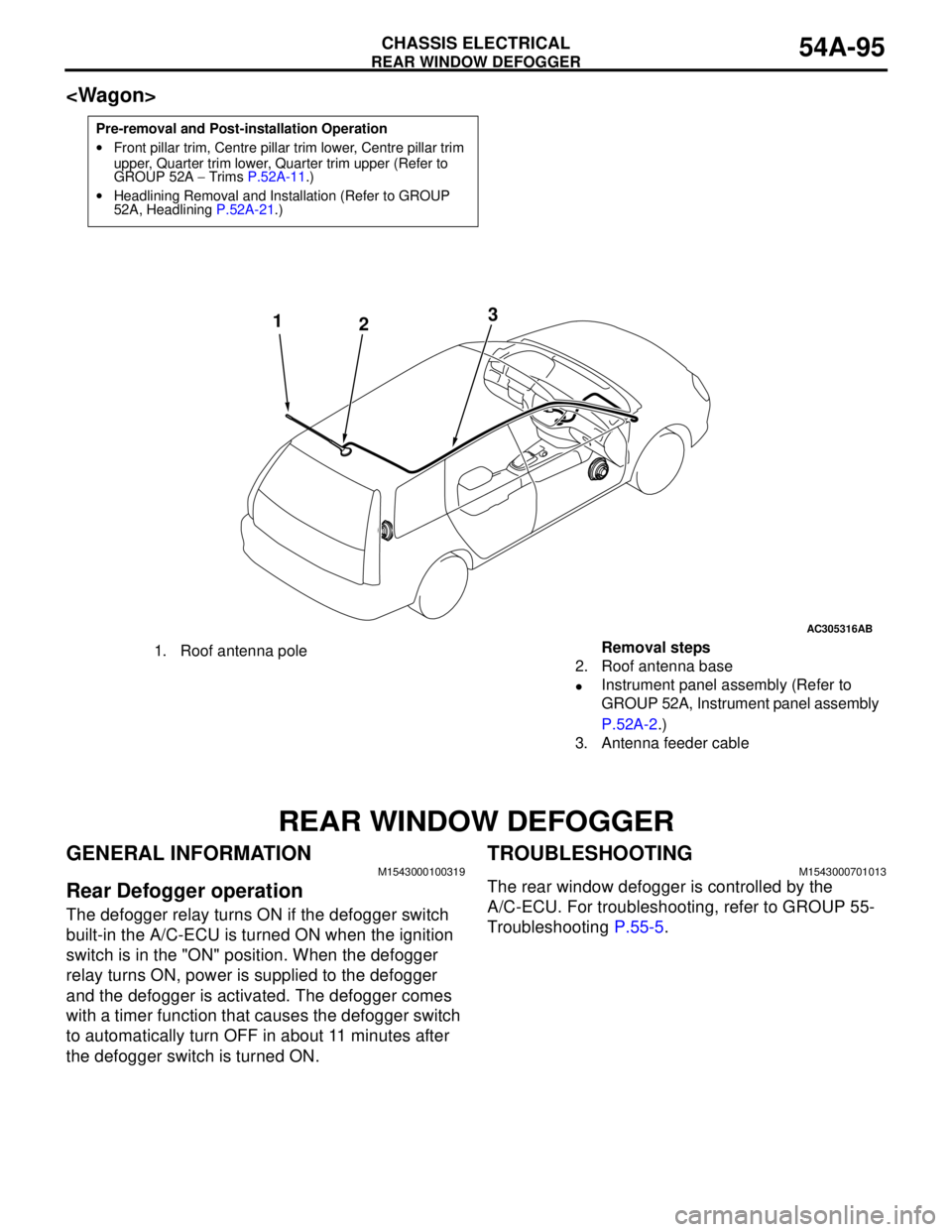
1. Roof antenna poleRemoval steps
2. Roof antenna base
•Instrument panel assembly (Refer to
GROUP 52A, Instrument panel assembly
P.52A-2.)
3. Antenna feeder cable
Page 560 of 788
ON-VEHICLE SERVICE
HEATER, AIR CONDITIONER AND VENTILATION55-76
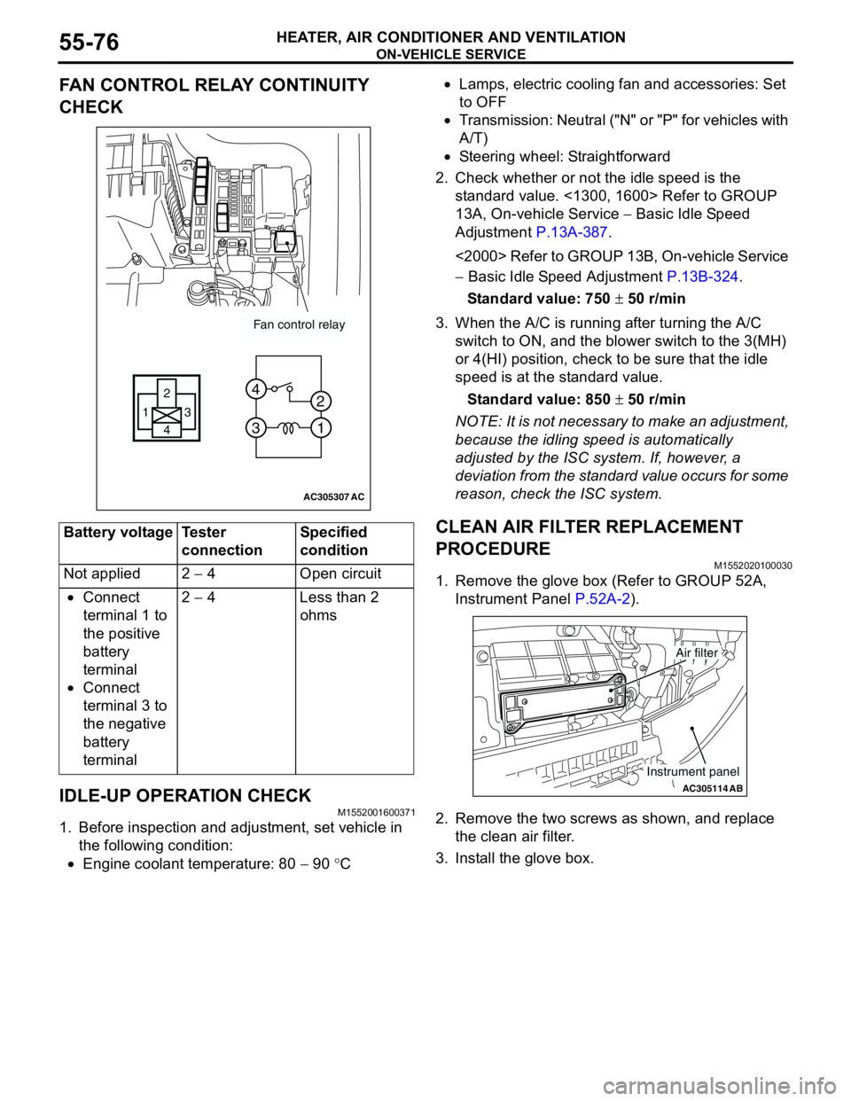
FAN CONTROL RELAY CONTINUITY
CHECK
IDLE-UP OPERATION CHECK
M1552001600371
1. Before inspection and adjustment, set vehicle in
the following condition:
•Engine coolant temperature: 80 − 90 °C•Lamps, electric cooling fan and accessories: Set
to OFF
•Transmission: Neutral ("N" or "P" for vehicles with
A/T)
•Steering wheel: Straightforward
2. Check whether or not the idle speed is the
standard value. <1300, 1600> Refer to GROUP
13A, On-vehicle Service − Basic Idle Speed
Adjustment P.13A-387.
<2000> Refer to GROUP 13B, On-vehicle Service
− Basic Idle Speed Adjustment P.13B-324.
Standard value: 750 ± 50 r/min
3. When the A/C is running after turning the A/C
switch to ON, and the blower switch to the 3(MH)
or 4(HI) position, check to be sure that the idle
speed is at the standard value.
Standard value: 850 ± 50 r/min
NOTE: It is not necessary to make an adjustment,
because the idling speed is automatically
adjusted by the ISC system. If, however, a
deviation from the standard value occurs for some
reason, check the ISC system.
CLEAN AIR FILTER REPLACEMENT
PROCEDURE
M1552020100030
1. Remove the glove box (Refer to GROUP 52A,
Instrument Panel P.52A-2).
2. Remove the two screws as shown, and replace
the clean air filter.
3. Install the glove box. Battery voltage Tester
connectionSpecified
condition
Not applied 2 − 4 Open circuit
•Connect
terminal 1 to
the positive
battery
terminal
•Connect
terminal 3 to
the negative
battery
terminal2 − 4 Less than 2
ohms
AC305307
Fan control relay
13
4 2
3 4
1 2
AC
AC305114AB
Air filter
Instrument panel
Page 565 of 788
HEATER UNIT, HEATER CORE, BLOWER ASSEMBLY AND EVAPORATOR UNIT
HEATER, AIR CONDITIONER AND VENTILATION55-81
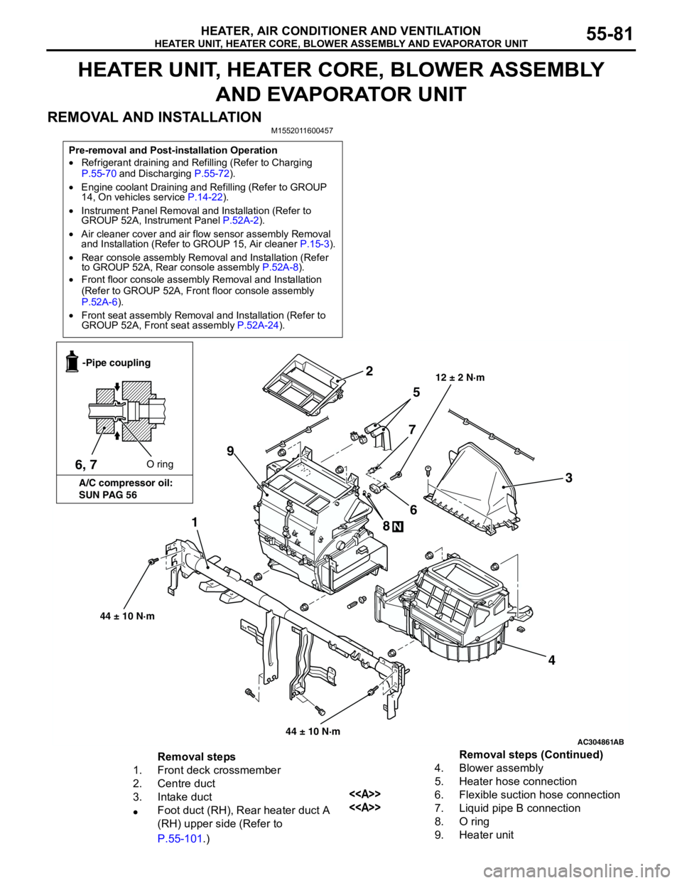
HEATER UNIT, HEATER CORE, BLOWER ASSEMBLY
AND EVAPORATOR UNIT
REMOVAL AND INSTALLATION
M1552011600457
Pre-removal and Post-installation Operation
•Refrigerant draining and Refilling (Refer to Charging
P.55-70 and Discharging P.55-72).
•Engine coolant Draining and Refilling (Refer to GROUP
14, On vehicles service P.14-22).
•Instrument Panel Removal and Installation (Refer to
GROUP 52A, Instrument Panel P.52A-2).
•Air cleaner cover and air flow sensor assembly Removal
and Installation (Refer to GROUP 15, Air cleaner P.15-3).
•Rear console assembly Removal and Installation (Refer
to GROUP 52A, Rear console assembly P.52A-8).
•Front floor console assembly Removal and Installation
(Refer to GROUP 52A, Front floor console assembly
P.52A-6).
•Front seat assembly Removal and Installation (Refer to
GROUP 52A, Front seat assembly P.52A-24).
AC304861
1
2
3
4 5
6
7
8
N
9
AB
12 ± 2 N·m
6, 7O ring -Pipe coupling
A/C compressor oil:
SUN PAG 56
44 ± 10 N·m
44 ± 10 N·m
Removal steps
1. Front deck crossmember
2. Centre duct
3. Intake duct
•Foot duct (RH), Rear heater duct A
(RH) upper side (Refer to
P.55-101.)4. Blower assembly
5. Heater hose connection
<>6. Flexible suction hose connection
<>7. Liquid pipe B connection
8. O ring
9. Heater unitRemoval steps (Continued)
Page 569 of 788
BLOWERMOTOR, RESISTOR AND OUTSIDE/ INSIDE AIR SELECTION DAMPER CONTROL MOTOR
HEATER, AIR CONDITIONER AND VENTILATION55-85
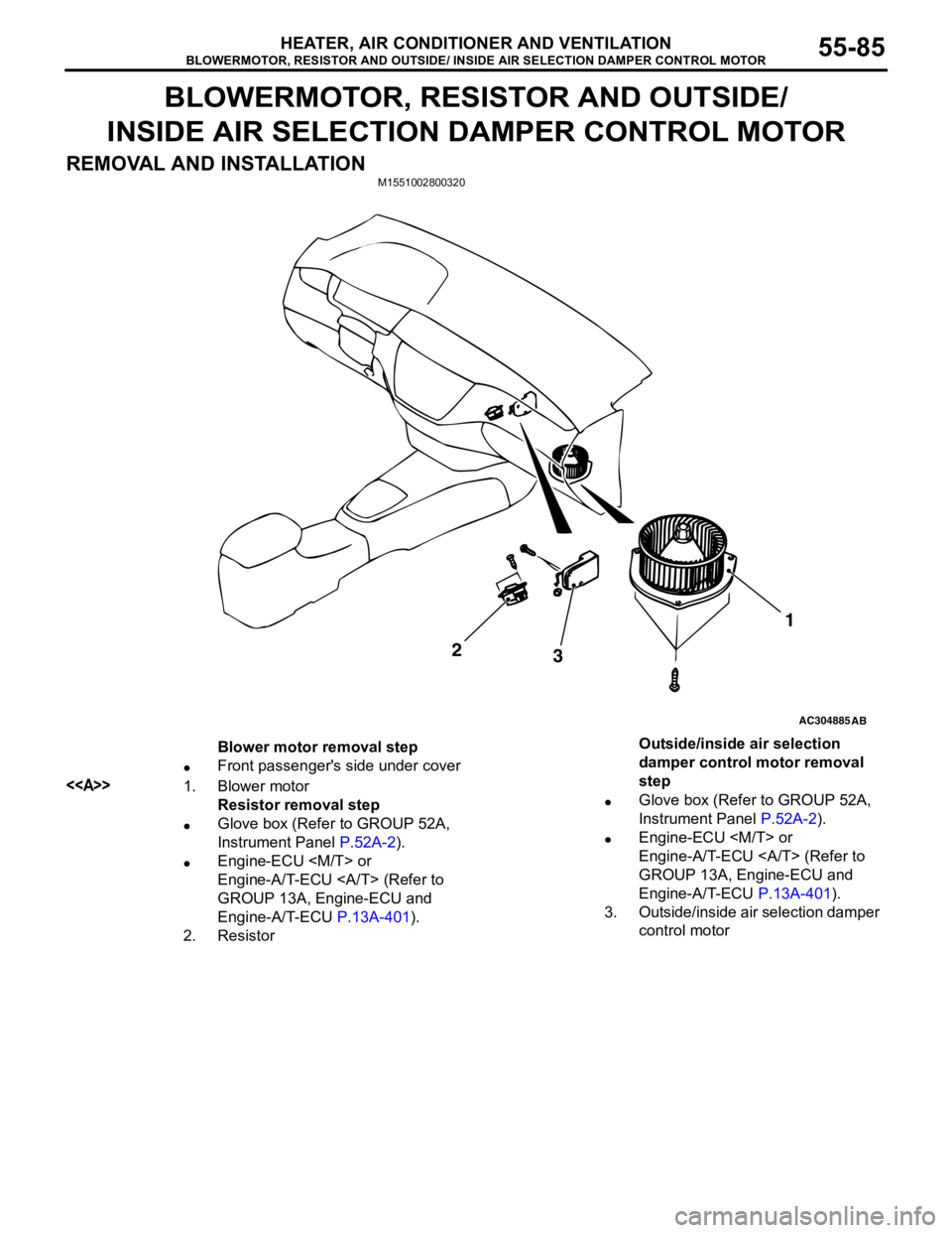
BLOWERMOTOR, RESISTOR AND OUTSIDE/
INSIDE AIR SELECTION DAMPER CONTROL MOTOR
REMOVAL AND INSTALLATION
M1551002800320
AC304885AB
2
31
Blower motor removal step
•Front passenger's side under cover
<>1. Blower motor
Resistor removal step
•Glove box (Refer to GROUP 52A,
Instrument Panel P.52A-2).
•Engine-ECU
Engine-A/T-ECU (Refer to
GROUP 13A, Engine-ECU and
Engine-A/T-ECU P.13A-401).
2. ResistorOutside/inside air selection
damper control motor removal
step
•Glove box (Refer to GROUP 52A,
Instrument Panel P.52A-2).
•Engine-ECU
Engine-A/T-ECU (Refer to
GROUP 13A, Engine-ECU and
Engine-A/T-ECU P.13A-401).
3. Outside/inside air selection damper
control motor
Page 572 of 788
EVAPORATOR ASSEMBLY
HEATER, AIR CONDITIONER AND VENTILATION55-88
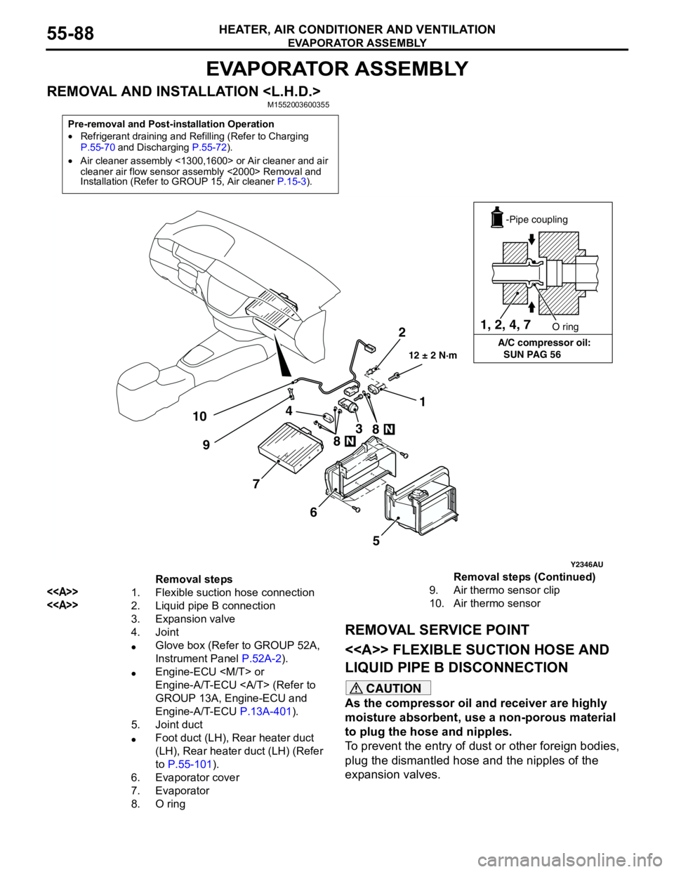
EVAPORATOR ASSEMBLY
REMOVAL AND INSTALLATION
REMOVAL SERVICE POINT
<> FLEXIBLE SUCTION HOSE AND
LIQUID PIPE B DISCONNECTION
CAUTION
As the compressor oil and receiver are highly
moisture absorbent, use a non-porous material
to plug the hose and nipples.
To prevent the entry of dust or other foreign bodies,
plug the dismantled hose and the nipples of the
expansion valves.
Pre-removal and Post-installation Operation
•Refrigerant draining and Refilling (Refer to Charging
P.55-70 and Discharging P.55-72).
•Air cleaner assembly <1300,1600> or Air cleaner and air
cleaner air flow sensor assembly <2000> Removal and
Installation (Refer to GROUP 15, Air cleaner P.15-3).
Y2346AU
1, 2, 4, 7
A/C compressor oil:
SUN PAG 56O ring
-Pipe coupling
2
101
3 4
7
6
5 98
8
12 ± 2 N·m
Removal steps
<>1. Flexible suction hose connection
<>2. Liquid pipe B connection
3. Expansion valve
4. Joint
•Glove box (Refer to GROUP 52A,
Instrument Panel P.52A-2).
•Engine-ECU
Engine-A/T-ECU (Refer to
GROUP 13A, Engine-ECU and
Engine-A/T-ECU P.13A-401).
5. Joint duct
•Foot duct (LH), Rear heater duct
(LH), Rear heater duct (LH) (Refer
to P.55-101).
6. Evaporator cover
7. Evaporator
8. O ring 9. Air thermo sensor clip
10. Air thermo sensorRemoval steps (Continued)
Page 573 of 788
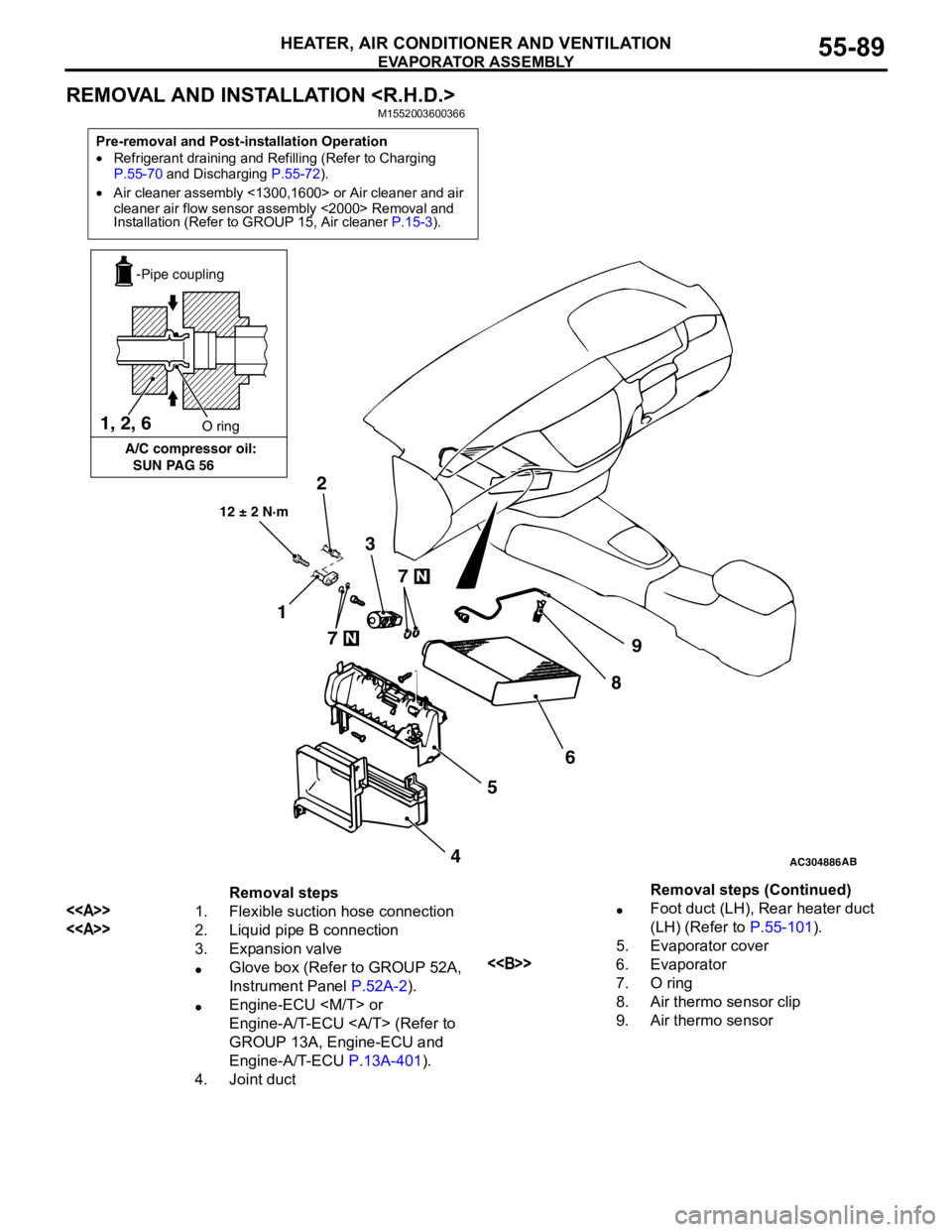
EVAPORATOR ASSEMBLY
HEATER, AIR CONDITIONER AND VENTILATION55-89
REMOVAL AND INSTALLATION
Pre-removal and Post-installation Operation
•Refrigerant draining and Refilling (Refer to Charging
P.55-70 and Discharging P.55-72).
•Air cleaner assembly <1300,1600> or Air cleaner and air
cleaner air flow sensor assembly <2000> Removal and
Installation (Refer to GROUP 15, Air cleaner P.15-3).
AC304886AB
12 ± 2 N·m
7
7
2
1
9
8
6
5
4 3 1, 2, 6
A/C compressor oil:
SUN PAG 56O ring
-Pipe coupling
Removal steps
<>1. Flexible suction hose connection
<>2. Liquid pipe B connection
3. Expansion valve
•Glove box (Refer to GROUP 52A,
Instrument Panel P.52A-2).
•Engine-ECU
Engine-A/T-ECU (Refer to
GROUP 13A, Engine-ECU and
Engine-A/T-ECU P.13A-401).
4. Joint duct•Foot duct (LH), Rear heater duct
(LH) (Refer to P.55-101).
5. Evaporator cover
<>6. Evaporator
7. O ring
8. Air thermo sensor clip
9. Air thermo sensorRemoval steps (Continued)
Page 585 of 788
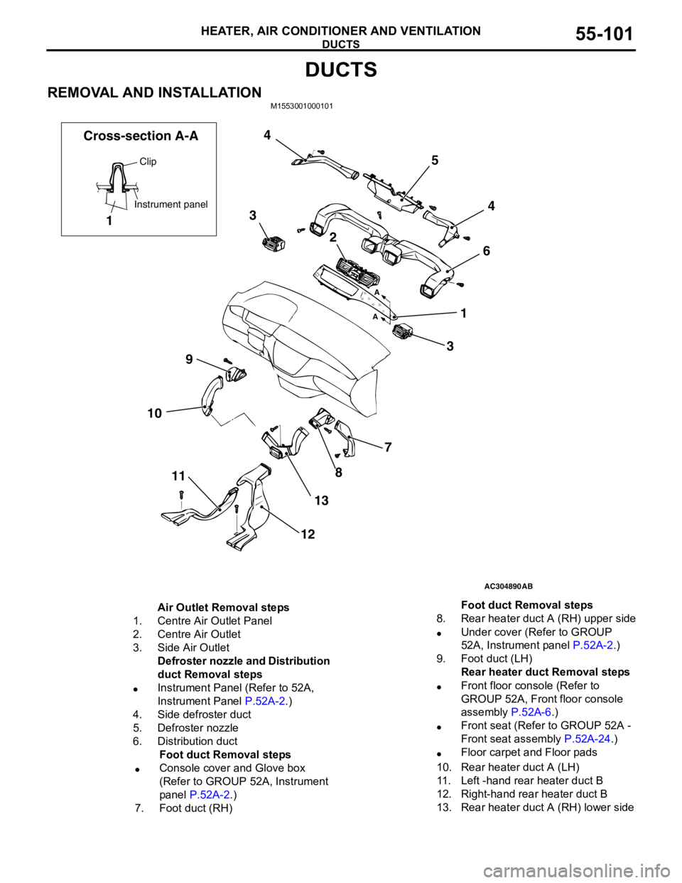
DUCTS
HEATER, AIR CONDITIONER AND VENTILATION55-101
DUCTS
REMOVAL AND INSTALLATIONM1553001000101
AC304890
7
8
13
12 11 109364 5 4
3
2
1
AB A
A
Clip
Instrument panel
1 Cross-section A-A
Air Outlet Removal steps
1. Centre Air Outlet Panel
2. Centre Air Outlet
3. Side Air Outlet
Defroster nozzle and Distribution
duct Removal steps
•Instrument Panel (Refer to 52A,
Instrument Panel P.52A-2.)
4. Side defroster duct
5. Defroster nozzle
6. Distribution duct
Foot duct Removal steps
•Console cover and Glove box
(Refer to GROUP 52A, Instrument
panel P.52A-2.)
7. Foot duct (RH)8. Rear heater duct A (RH) upper side
•Under cover (Refer to GROUP
52A, Instrument panel P.52A-2.)
9. Foot duct (LH)
Rear heater duct Removal steps
•Front floor console (Refer to
GROUP 52A, Front floor console
assembly P.52A-6.)
•Front seat (Refer to GROUP 52A -
Front seat assembly P.52A-24.)
•Floor carpet and Floor pads
10. Rear heater duct A (LH)
11. Left -hand rear heater duct B
12. Right-hand rear heater duct B
13. Rear heater duct A (RH) lower sideFoot duct Removal steps