Front suspensión MITSUBISHI LANCER 2005 Owner's Manual
[x] Cancel search | Manufacturer: MITSUBISHI, Model Year: 2005, Model line: LANCER, Model: MITSUBISHI LANCER 2005Pages: 788, PDF Size: 45.98 MB
Page 198 of 788
Page 199 of 788
STABILIZER BAR
FRONT SUSPENSION33-17
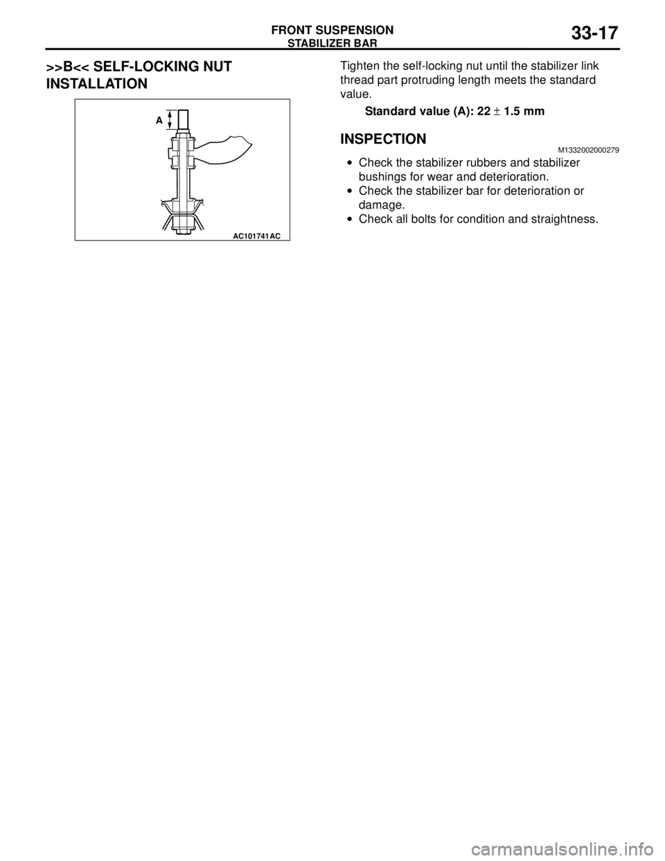
>>B<< SELF-LOCKING NUT
INSTALLATIONTighten the self-locking nut until the stabilizer link
thread part protruding length meets the standard
value.
Standard value (A): 22 ± 1.5 mm
INSPECTIONM1332002000279
•Check the stabilizer rubbers and stabilizer
bushings for wear and deterioration.
•Check the stabilizer bar for deterioration or
damage.
•Check all bolts for condition and straightness.
AC101741AC
A
Page 206 of 788
ON-VEHICLE SERVICE
REAR SUSPENSION34-6
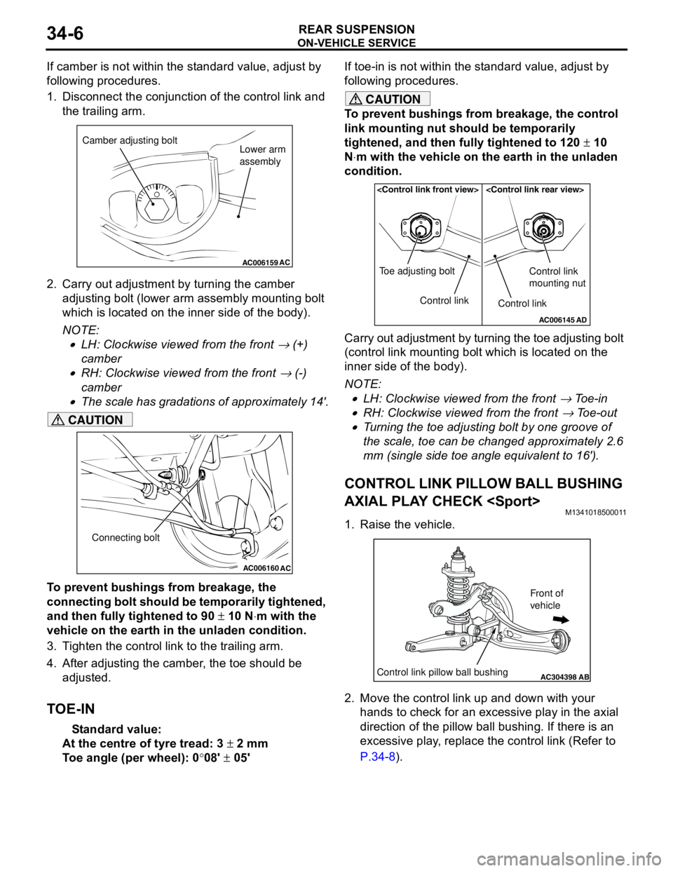
If camber is not within the standard value, adjust by
following procedures.
1. Disconnect the conjunction of the control link and
the trailing arm.
2. Carry out adjustment by turning the camber
adjusting bolt (lower arm assembly mounting bolt
which is located on the inner side of the body).
NOTE: .
•LH: Clockwise viewed from the front → (+)
camber
•RH: Clockwise viewed from the front → (-)
camber
•The scale has gradations of approximately 14'.
CAUTION
To prevent bushings from breakage, the
connecting bolt should be temporarily tightened,
and then fully tightened to 90 ± 10 N⋅m with the
vehicle on the earth in the unladen condition.
3. Tighten the control link to the trailing arm.
4. After adjusting the camber, the toe should be
adjusted.
TOE-IN
Standard value:
At the centre of tyre tread: 3 ± 2 mm
Toe angle (per wheel): 0°08' ± 05'If toe-in is not within the standard value, adjust by
following procedures.
CAUTION
To prevent bushings from breakage, the control
link mounting nut should be temporarily
tightened, and then fully tightened to 120 ± 10
N⋅m with the vehicle on the earth in the unladen
condition.
Carry out adjustment by turning the toe adjusting bolt
(control link mounting bolt which is located on the
inner side of the body).
NOTE: .
•LH: Clockwise viewed from the front → Toe-in
•RH: Clockwise viewed from the front → Toe-out
•Turning the toe adjusting bolt by one groove of
the scale, toe can be changed approximately 2.6
mm (single side toe angle equivalent to 16').
CONTROL LINK PILLOW BALL BUSHING
AXIAL PLAY CHECK
M1341018500011
1. Raise the vehicle.
2. Move the control link up and down with your
hands to check for an excessive play in the axial
direction of the pillow ball bushing. If there is an
excessive play, replace the control link (Refer to
P.34-8).
AC006159AC
Camber adjusting bolt
Lower arm
assembly
AC006160
AC
Connecting bolt
AC006145AD
Control link Toe adjusting boltControl link
Control link
mounting nut
AC304398ABControl link pillow ball bushing
Front of
vehicle
Page 207 of 788

ON-VEHICLE SERVICE
REAR SUSPENSION34-7
UPPER ARM PILLOW BALL BUSHING
AXIAL PLAY CHECK
M1341018400014
1. Raise the vehicle.
2. Move the upper arm up and down with your hands
to check for an excessive play in the axial
direction of the pillow ball bushing. If there is an
excessive play, replace the upper arm (Refer to
P.34-8).
LOWER ARM PILLOW BALL BUSHING
AXIAL PLAY CHECK
M1341016900057
1. Raise the vehicle.
2. Remove the stabilizer link and shock absorber
from the lower arm assembly.3. Move the lower arm up and down with your hands
to check for an excessive play in the axial
direction of the pillow ball bushing. If there is an
excessive play, replace the lower arm pillow ball
bushing (Refer to P.34-10).
4. After inspection, install the stabilizer link and
shock absorber to the lower arm assembly (Refer
to P.34-8).
STABILIZER LINK BALL JOINT DUST
COVER INSPECTION
M1341012800274
1. Check stabilizer link ball joint dust covers for
cracks or damage by pushing it with your finger.
2. If a dust cover is cracked or damaged, replace the
stabilizer link assembly.
NOTE: Cracks or damage to the dust cover may
cause damage to the ball joint.
AC304398AC
Upper arm pillow
ball bushing
Front of
vehicle
AC304398ADLower arm pillow ball bushing
Front of
vehicle
Page 213 of 788
Page 454 of 788
HEADLAMP
CHASSIS ELECTRICAL54A-66
HEADLAMP
SERVICE SPECIFICATIONSM1542000300332
TROUBLESHOOTING M1542000701281
Features the headlamp automatic shutdown function
to avoid battery drain when the headlamps are left
on. The main features are as follows:
•Extinguishes automatically in three minutes if the
ignition switch is turned off with the lighting switch
on.
•Extinguishes in one second if the driver's door is
opened within that 3-minute period.
•If the headlamps are turned on with the ignition
switch off, the headlamps and tail lamps will
extinguish in three minutes after the driver's door
is opened or closed.
The headlamps are controlled by the Smart Wiring
System (SWS). For troubleshooting, refer to
respective Groups below.
•Not using SWS monitor: GROUP 54B, SWS
Troubleshooting P.54B-38.
•Using SWS monitor: GROUP 54C, SWS
Troubleshooting P.54C-22.
ON-VEHICLE SERVICE
HEADLAMP AIMING
M1542000900538
PRE-AIMING INSTRUCTIONS
1. Inspect for badly rusted or faulty headlamp
assemblies.
2. These conditions must be corrected before a
satisfactory adjustment can be made.
3. Inspect tyre inflation, and adjust if it is necessary.
4. If the fuel tank is not full, place a weight in luggage
room of the vehicle to simulate weight of a full
tank (0.8 kg per litre).
5. There should be no other load in the vehicle other
than driver or substituted weight of approximately
75 kg placed in driver's position.
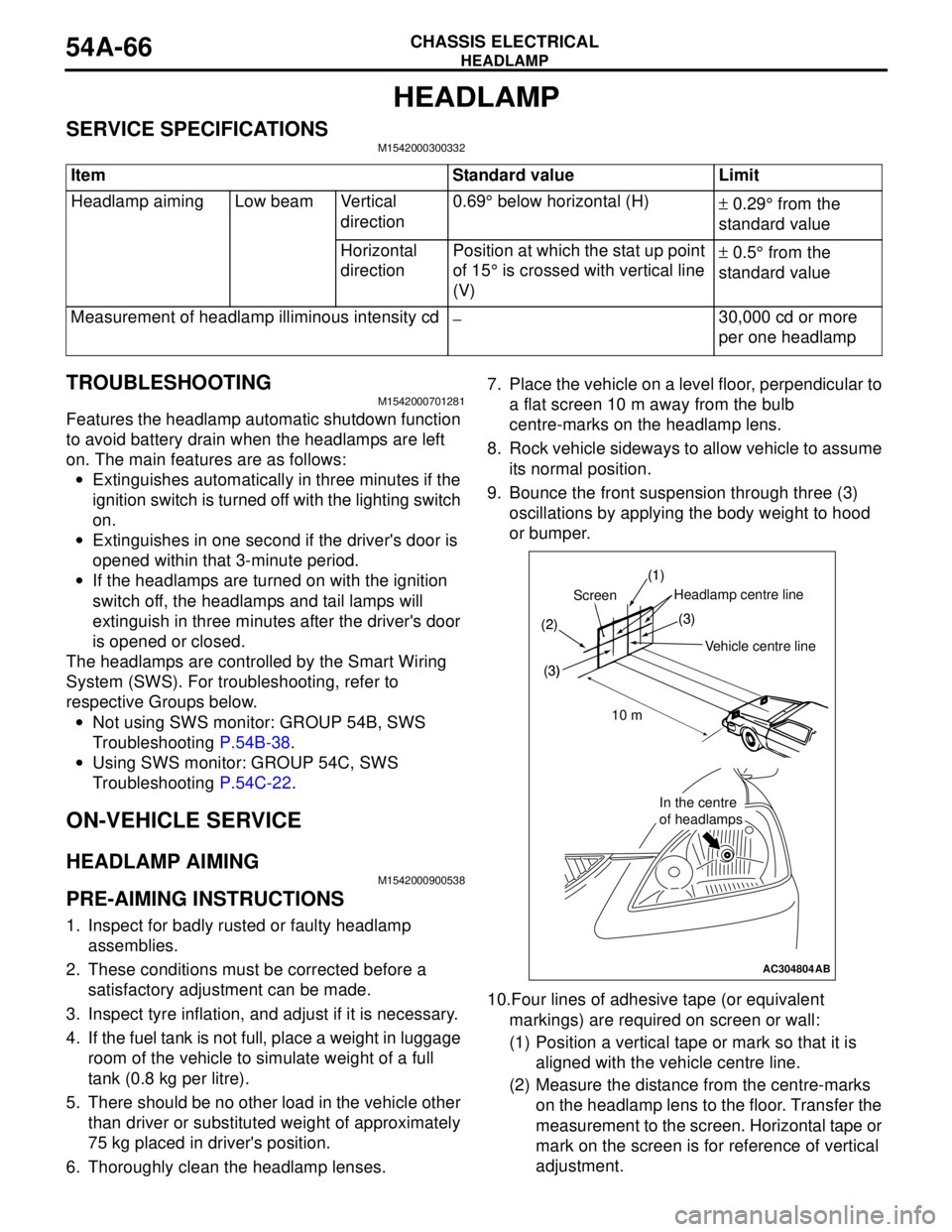
6. Thoroughly clean the headlamp lenses.7. Place the vehicle on a level floor, perpendicular to
a flat screen 10 m away from the bulb
centre-marks on the headlamp lens.
8. Rock vehicle sideways to allow vehicle to assume
its normal position.
9. Bounce the front suspension through three (3)
oscillations by applying the body weight to hood
or bumper.
10.Four lines of adhesive tape (or equivalent
markings) are required on screen or wall:
(1) Position a vertical tape or mark so that it is
aligned with the vehicle centre line.
(2) Measure the distance from the centre-marks
on the headlamp lens to the floor. Transfer the
measurement to the screen. Horizontal tape or
mark on the screen is for reference of vertical
adjustment. Item Standard value Limit
Headlamp aiming Low beam Vertical
direction0.69° below horizontal (H)
± 0.29° from the
standard value
Horizontal
directionPosition at which the stat up point
of 15° is crossed with vertical line
(V)± 0.5° from the
standard value
Measurement of headlamp illiminous intensity cd
−30,000 cd or more
per one headlamp
AC304804
(1)
(2)
(3)
Headlamp centre line
Vehicle crntre line Screen
(3)
10 m
In the centre
of headlamps
(1)
(2)
(3)(3)
In the centre
of headlamps
AB
Vehicle centre line
ScreenHeadlamp centre line
10 m