engine MITSUBISHI LANCER 2005 Owner's Manual
[x] Cancel search | Manufacturer: MITSUBISHI, Model Year: 2005, Model line: LANCER, Model: MITSUBISHI LANCER 2005Pages: 788, PDF Size: 45.98 MB
Page 27 of 788
TROUBLESHOOTING
ENGINE COOLING14-13
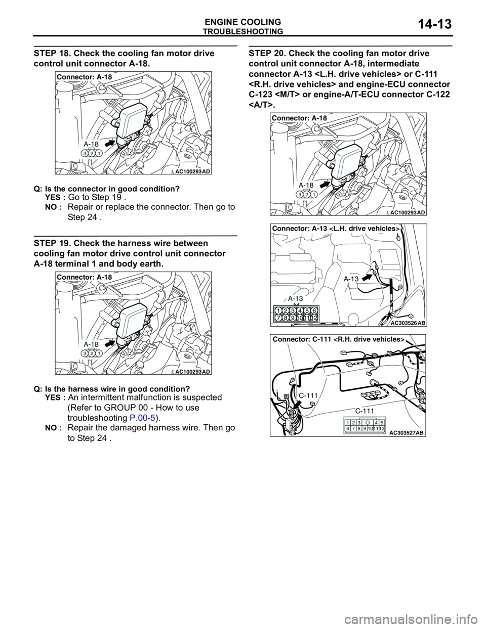
STEP 18. Check the cooling fan motor drive
control unit connector A-18.
Q: Is the connector in good condition?
YES :
Go to Step 19 .
NO : Repair or replace the connector. Then go to
Step 24 .
STEP 19. Check the harness wire between
cooling fan motor drive control unit connector
A-18 terminal 1 and body earth.
Q: Is the harness wire in good condition?
YES :
An intermittent malfunction is suspected
(Refer to GROUP 00 - How to use
troubleshooting P.00-5).
NO : Repair the damaged harness wire. Then go
to Step 24 .
STEP 20. Check the cooling fan motor drive
control unit connector A-18, intermediate
connector A-13
C-123
.
AC100293
A-18
321
Connector: A-18
AD
AC100293
A-18
321
Connector: A-18
AD
AC100293
A-18
321
Connector: A-18
AD
AC303526
Connector: A-13
AB
A-13
A-13
AC303527
Connector: C-111
AB
C-111
C-111
615
121179
810234
Page 28 of 788
TROUBLESHOOTING
ENGINE COOLING14-14
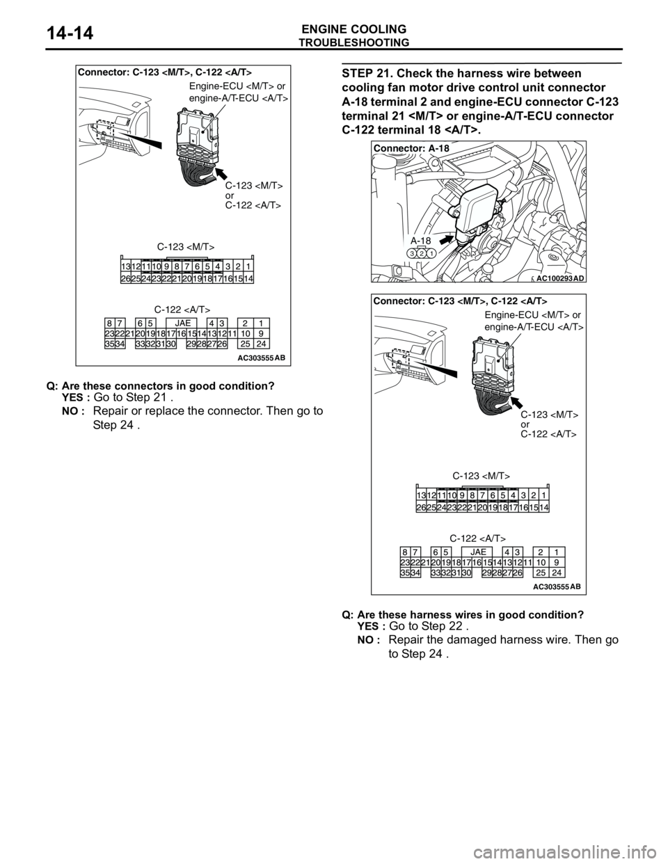
Q: Are these connectors in good condition?
YES :
Go to Step 21 .
NO : Repair or replace the connector. Then go to
Step 24 .
STEP 21. Check the harness wire between
cooling fan motor drive control unit connector
A-18 terminal 2 and engine-ECU connector C-123
terminal 21
C-122 terminal 18 .
Q: Are these harness wires in good condition?
YES :
Go to Step 22 .
NO : Repair the damaged harness wire. Then go
to Step 24 .
AC303555AB
Connector: C-123
C-123
or
C-122
C-123
Engine-ECU
engine-A/T-ECU
C-122
AC100293
A-18
321
Connector: A-18
AD
AC303555AB
Connector: C-123
C-123
or
C-122
C-123
Engine-ECU
engine-A/T-ECU
C-122
Page 29 of 788
TROUBLESHOOTING
ENGINE COOLING14-15
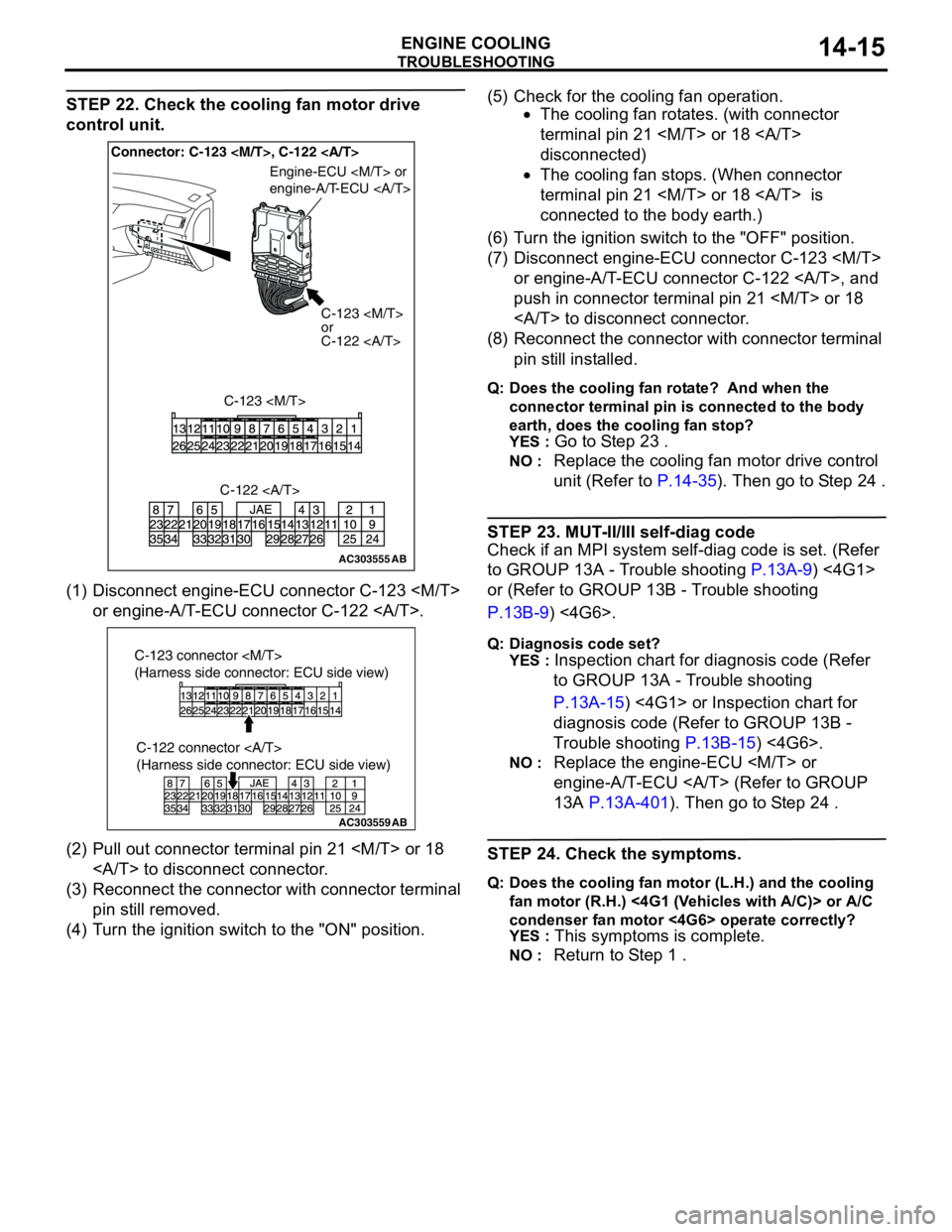
STEP 22. Check the cooling fan motor drive
control unit.
(1) Disconnect engine-ECU connector C-123
or engine-A/T-ECU connector C-122 .
(2) Pull out connector terminal pin 21
to disconnect connector.
(3) Reconnect the connector with connector terminal
pin still removed.
(4) Turn the ignition switch to the "ON" position.(5) Check for the cooling fan operation.
•The cooling fan rotates. (with connector
terminal pin 21
disconnected)
•The cooling fan stops. (When connector
terminal pin 21
connected to the body earth.)
(6) Turn the ignition switch to the "OFF" position.
(7) Disconnect engine-ECU connector C-123
or engine-A/T-ECU connector C-122 , and
push in connector terminal pin 21
to disconnect connector.
(8) Reconnect the connector with connector terminal
pin still installed.
Q: Does the cooling fan rotate? And when the
connector terminal pin is connected to the body
earth, does the cooling fan stop?
YES :
Go to Step 23 .
NO : Replace the cooling fan motor drive control
unit (Refer to P.14-35). Then go to Step 24 .
STEP 23. MUT-II/III self-diag code
Check if an MPI system self-diag code is set. (Refer
to GROUP 13A - Trouble shooting P.13A-9) <4G1>
or (Refer to GROUP 13B - Trouble shooting
P.13B-9) <4G6>.
Q: Diagnosis code set?
YES :
Inspection chart for diagnosis code (Refer
to GROUP 13A - Trouble shooting
P.13A-15) <4G1> or Inspection chart for
diagnosis code (Refer to GROUP 13B -
Trouble shooting P.13B-15) <4G6>.
NO : Replace the engine-ECU
engine-A/T-ECU (Refer to GROUP
13A P.13A-401). Then go to Step 24 .
STEP 24. Check the symptoms.
Q: Does the cooling fan motor (L.H.) and the cooling
fan motor (R.H.) <4G1 (Vehicles with A/C)> or A/C
condenser fan motor <4G6> operate correctly?
YES :
This symptoms is complete.
NO : Return to Step 1 .
AC303555AB
Connector: C-123
C-123
or
C-122
C-123
Engine-ECU
engine-A/T-ECU
C-122
AC303559
C-122 connector
(Harness side connector: ECU side view)
AB
C-123 connector
(Harness side connector: ECU side view)
Page 30 of 788
TROUBLESHOOTING
ENGINE COOLING14-16
INSPECTION PROCEDURE 2: Cooling Fan (L.H.) and Cooling Fan (R.H.) <4G1 (Vehicles with A/C)> or
A/C Condenser Fan <4G6> do not Change Speed or Stop
COOLING FAN (L.H.) AND COOLING FAN
(R.H.) OR A/C CONDENSER FAN DRIVE
CIRCUIT
Refer to P.14-6.
CIRCUIT OPERATION
Refer to P.14-6.
TECHNICAL DESCRIPTION
•If the communication line wiring harness between
the cooling fan motor drive control unit and the
engine-ECU
is open, the cooling fan motor (L.H.) and
the cooling fan motor (R.H.) <4G1 (Vehicles with
A/C)>, or the A/C condenser fan motor <4G6>
rotate to prevent the engine from overheating.
•If the system voltage is continuously supplied to
the cooling fan motor drive control unit by a fan
motor relay malfunction and a short circuit on the
cooling fan motor drive control unit power supply
wiring harness, the cooling fan motor (L.H.) and
the cooling fan motor (R.H.) <4G1 (Vehicles with
A/C)>, or the A/C condenser fan motor <4G6>
rotate.
•The cause could also be a malfunction of the
cooling fan motor (L.H.).
•The cause could also be a malfunction of input
signal from the A/C switch, the water temperature
sensor unit and the vehicle speed sensor
or the output shaft speed sensor to the
engine-ECU
•The cause could also be a malfunction of the
cooling fan motor drive control unit or the
engine-ECU
TROUBLESHOOTING HINTS
•Malfunction of fan control relay
•Malfunction of cooling fan motor (L.H.)
•Malfunction of cooling fan motor drive control unit
•Malfunction of engine-ECU
engine-A/T-ECU
•Damaged wiring harness or connector
DIAGNOSIS
STEP 1. Check the fan control relay.
Refer to P.14-24.
Q: Is the fan control relay in good condition?
YES :
Go to Step 2 .
NO : Replace the fan control relay. Then go to
Step 8 .
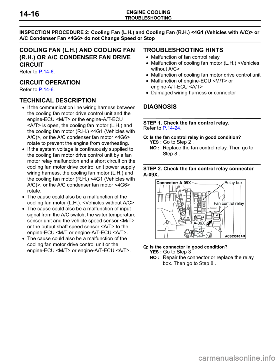
STEP 2. Check the fan control relay connector
A-09X.
Q: Is the connector in good condition?
YES :
Go to Step 3 .
NO : Repair the connector or replace the relay
box. Then go to Step 8 .
AC303510AB
Fan control relay
Relay boxConnector: A-09X
A-09X
Page 31 of 788
TROUBLESHOOTING
ENGINE COOLING14-17
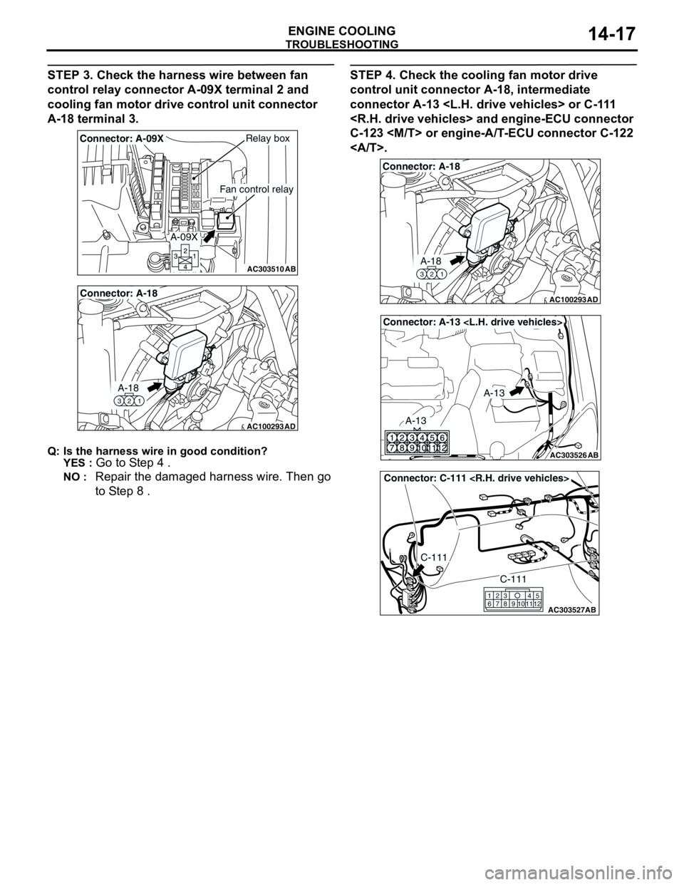
STEP 3. Check the harness wire between fan
control relay connector A-09X terminal 2 and
cooling fan motor drive control unit connector
A-18 terminal 3.
Q: Is the harness wire in good condition?
YES :
Go to Step 4 .
NO : Repair the damaged harness wire. Then go
to Step 8 .
STEP 4. Check the cooling fan motor drive
control unit connector A-18, intermediate
connector A-13
C-123
.
AC303510AB
Fan control relay
Relay boxConnector: A-09X
A-09X
AC100293
A-18
321
Connector: A-18
AD
AC100293
A-18
321
Connector: A-18
AD
AC303526
Connector: A-13
AB
A-13
A-13
AC303527
Connector: C-111
AB
C-111
C-111
615
121179
810234
Page 32 of 788
TROUBLESHOOTING
ENGINE COOLING14-18
Q: Are these connectors in good condition?
YES :
Go to Step 5 .
NO : Repair or replace the connector. Then go to
Step 8 .
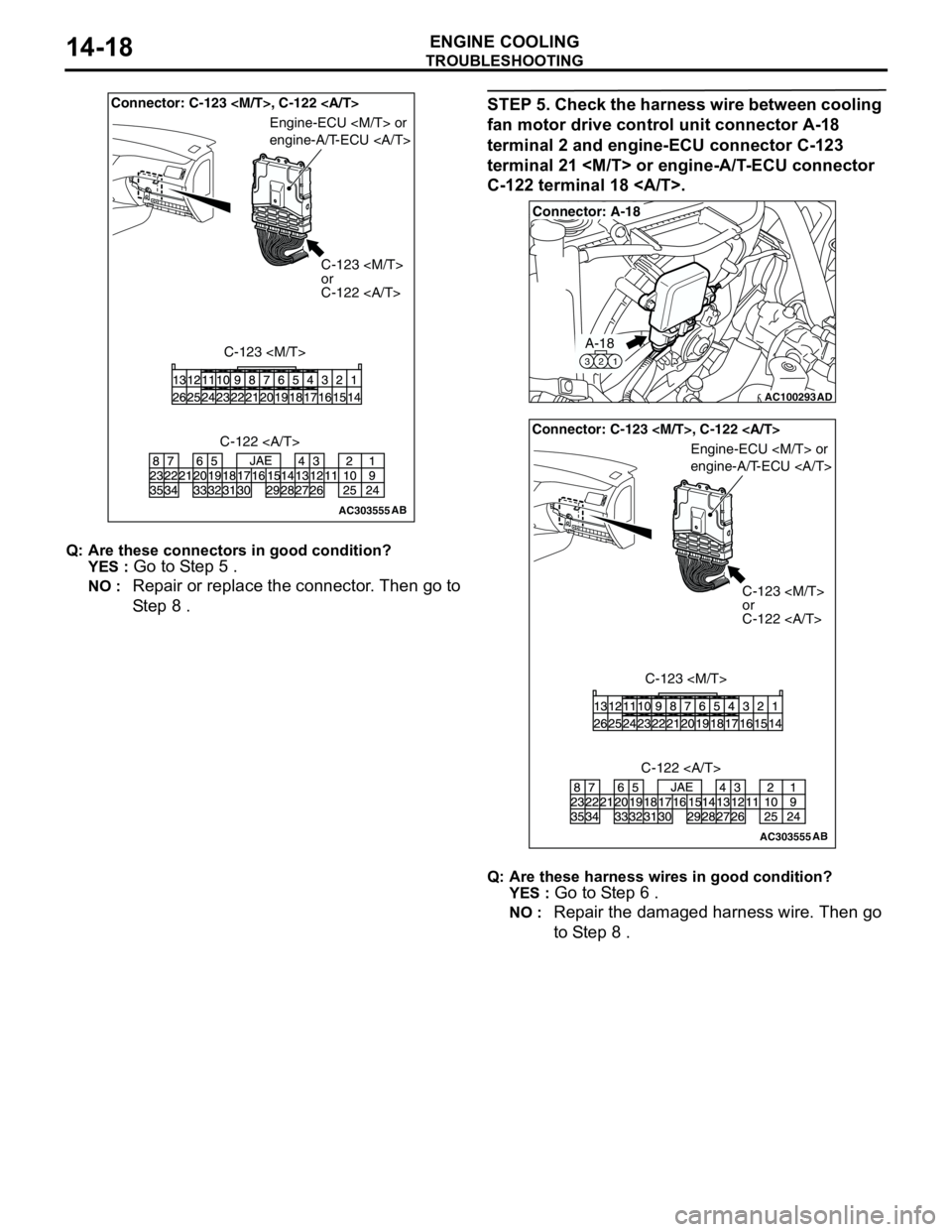
STEP 5. Check the harness wire between cooling
fan motor drive control unit connector A-18
terminal 2 and engine-ECU connector C-123
terminal 21
C-122 terminal 18 .
Q: Are these harness wires in good condition?
YES :
Go to Step 6 .
NO : Repair the damaged harness wire. Then go
to Step 8 .
AC303555AB
Connector: C-123
C-123
or
C-122
C-123
Engine-ECU
engine-A/T-ECU
C-122
AC100293
A-18
321
Connector: A-18
AD
AC303555AB
Connector: C-123
C-123
or
C-122
C-123
Engine-ECU
engine-A/T-ECU
C-122
Page 33 of 788
TROUBLESHOOTING
ENGINE COOLING14-19
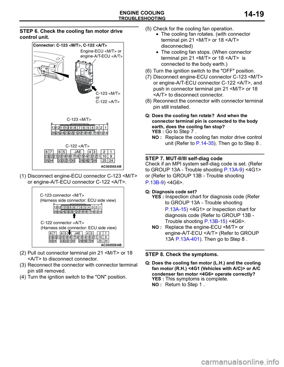
STEP 6. Check the cooling fan motor drive
control unit.
(1) Disconnect engine-ECU connector C-123
or engine-A/T-ECU connector C-122 .
(2) Pull out connector terminal pin 21
to disconnect connector.
(3) Reconnect the connector with connector terminal
pin still removed.
(4) Turn the ignition switch to the "ON" position.(5) Check for the cooling fan operation.
•The cooling fan rotates. (with connector
terminal pin 21
disconnected)
•The cooling fan stops. (When connector
terminal pin 21
connected to the body earth.)
(6) Turn the ignition switch to the "OFF" position.
(7) Disconnect engine-ECU connector C-123
or engine-A/T-ECU connector C-122 , and
push in connector terminal pin 21
to disconnect connector.
(8) Reconnect the connector with connector terminal
pin still installed.
Q: Does the cooling fan rotate? And when the
connector terminal pin is connected to the body
earth, does the cooling fan stop?
YES :
Go to Step 7 .
NO : Replace the cooling fan motor drive control
unit (Refer to P.14-35). Then go to Step 8 .
STEP 7. MUT-II/III self-diag code
Check if an MPI system self-diag code is set. (Refer
to GROUP 13A - Trouble shooting P.13A-9) <4G1>
or (Refer to GROUP 13B - Trouble shooting
P.13B-9) <4G6>.
Q: Diagnosis code set?
YES :
Inspection chart for diagnosis code (Refer
to GROUP 13A - Trouble shooting
P.13A-15) <4G1> or Inspection chart for
diagnosis code (Refer to GROUP 13B -
Trouble shooting P.13B-15) <4G6>.
NO : Replace the engine-ECU
engine-A/T-ECU (Refer to GROUP
13A P.13A-401). Then go to Step 8 .
STEP 8. Check the symptoms.
Q: Does the cooling fan motor (L.H.) and the cooling
fan motor (R.H.) <4G1 (Vehicles with A/C)> or A/C
condenser fan motor <4G6> operate correctly?
YES :
This symptoms is complete.
NO : Return to Step 1 .
AC303555AB
Connector: C-123
C-123
or
C-122
C-123
Engine-ECU
engine-A/T-ECU
C-122
AC303559
C-122 connector
(Harness side connector: ECU side view)
AB
C-123 connector
(Harness side connector: ECU side view)
Page 34 of 788
TROUBLESHOOTING
ENGINE COOLING14-20
INSPECTION PROCEDURE 3: Cooling Fan (L.H.) does not Operate {When Cooling Fan (R.H.) <4G1> or
A/C Condenser Fan <4G6> Operate}
COOLING FAN (L.H.) AND COOLING FAN
(R.H.) OR A/C CONDENSER FAN DRIVE
CIRCUIT
Refer to P.14-6.
CIRCUIT OPERATION
Refer to P.14-6.
TECHNICAL DESCRIPTION
The cause could be a malfunction of the cooling fan
motor (L.H.) or cooling fan motor drive control unit.
TROUBLESHOOTING HINTS
•Malfunction of cooling fan motor (L.H.)
•Malfunction of cooling fan motor drive control unit
DIAGNOSIS
STEP 1. Check the cooling fan motor (L.H.).
Refer to P.14-25.
Q: Is the cooling fan motor (L.H.) in good condition?
YES :
Go to Step 2 .
NO : Replace the cooling fan motor (L.H.) (Refer
to P.14-35). Then go to Step 3 .
STEP 2. Check the cooling fan motor drive
control unit.
Refer to P.14-23.
Q: Is the cooling fan motor drive control unit in good
condition?
YES :
Go to Step 3 .
NO : Replace the cooling fan motor drive control
unit (Refer to P.14-35). Then go to Step 3 .
STEP 3. Check the symptoms.
Q: Do the cooling fan (L.H.) operate (when the cooling
fan (R.H.) <4G1> or A/C condenser fan <4G6>
operate)?
YES :
This symptoms is complete.
NO : Return to Step 1 .
Page 35 of 788
TROUBLESHOOTING
ENGINE COOLING14-21
INSPECTION PROCEDURE 4: Cooling Fan (R.H.) <4G1> or A/C Condenser Fan <4G6> does not
Operate {When Cooling Fan (L.H.) Operate}
COOLING FAN (L.H.) AND COOLING FAN
(R.H.) OR A/C CONDENSER FAN DRIVE
CIRCUIT
Refer to P.14-6.
CIRCUIT OPERATION
Refer to P.14-6.
TECHNICAL DESCRIPTION
The cause could be a malfunction of the cooling fan
motor (R.H.) <4G1> or A/C condenser fan motor
<4G6> or cooling fan motor drive control unit.
TROUBLESHOOTING HINTS
•Malfunction of cooling fan motor (R.H.) <4G1> or
A/C condenser fan motor <4G6>
•Malfunction of cooling fan motor drive control unit
DIAGNOSIS
STEP 1. Check the cooling fan motor (R.H.)
<4G1> or A/C condenser fan motor <4G6>.
Cooling fan motor (R.H.) check. (Refer to P.14-25)
<4G1>.
A/C condenser fan motor check. (Refer to GROUP
55 P.55-97) <4G6>.
Q: Is the cooling fan motor (R.H.) <4G1> or A/C
condenser fan motor <4G6> in good condition?
YES :
Go to Step 2 .
NO : Replace the cooling fan motor (R.H.) (Refer
to P.14-35) <4G1> or A/C condenser fan
motor (Refer to GROUP 55 P.55-96)
<4G6>. Then go to Step 3 .
STEP 2. Check the cooling fan motor drive
control unit.
Refer to P.14-23.
Q: Is the cooling fan motor drive control unit in good
condition?
YES :
Go to Step 3 .
NO : Replace the cooling fan motor drive control
unit (Refer to P.14-35). Then go to Step 3 .
STEP 3. Check the symptoms.
Q: Do the cooling fan (R.H.) <4G1> or A/C condenser
fan <4G6> operate (when the cooling fan (L.H.)
operate)?
YES :
This symptoms is complete.
NO : Return to Step 1 .
Page 36 of 788
ON-VEHICLE SERVICE
ENGINE COOLING14-22
ON-VEHICLE SERVICE
ENGINE COOLANT LEAK CHECKM1141001000300
WARNING
When pressure testing the cooling system,
slowly release cooling system pressure to
avoid getting burned by hot coolant.
CAUTION
•Be sure to completely clean away any
moisture from the places checked.
•When the tester is taken out, be careful not to
spill any coolant.
•Be careful when installing and removing the
tester and when testing not to deform the
filler neck of the radiator.
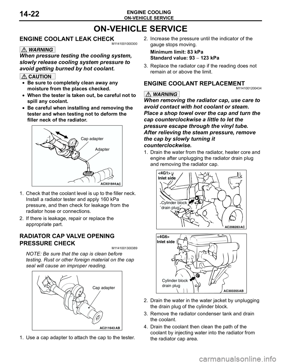
1. Check that the coolant level is up to the filler neck.
Install a radiator tester and apply 160 kPa
pressure, and then check for leakage from the
radiator hose or connections.
2. If there is leakage, repair or replace the
appropriate part.
RADIATOR CAP VALVE OPENING
PRESSURE CHECK
M1141001300389
NOTE: Be sure that the cap is clean before
testing. Rust or other foreign material on the cap
seal will cause an improper reading.
1. Use a cap adapter to attach the cap to the tester.2. Increase the pressure until the indicator of the
gauge stops moving.
Minimum limit: 83 kPa
Standard value: 93 − 123 kPa
3. Replace the radiator cap if the reading does not
remain at or above the limit.
ENGINE COOLANT REPLACEMENTM1141001200434
WARNING
When removing the radiator cap, use care to
avoid contact with hot coolant or steam.
Place a shop towel over the cap and turn the
cap counterclockwise a little to let the
pressure escape through the vinyl tube.
After relieving the steam pressure, remove
the cap by slowly turning it
counterclockwise.
1. Drain the water from the radiator, heater core and
engine after unplugging the radiator drain plug
and removing the radiator cap.
2. Drain the water in the water jacket by unplugging
the drain plug of the cylinder block.
3. Remove the radiator condenser tank and drain
the coolant.
4. Drain the coolant then clean the path of the
coolant by injecting water into the radiator from
the radiator cap area.
ACX01844
Cap adapter
Adapter
AC
AC211643AB
Cap adapter
AC208283AC
Cylinder block
drain plug
<4G1>
Inlet side
AC303355
<4G6>
Inlet side
Cylinder block
drain plug
AB