coolant level MITSUBISHI LANCER 2005 Workshop Manual
[x] Cancel search | Manufacturer: MITSUBISHI, Model Year: 2005, Model line: LANCER, Model: MITSUBISHI LANCER 2005Pages: 788, PDF Size: 45.98 MB
Page 10 of 788
ON-VEHICLE SERVICE
ENGINE LUBRICATION12-4
ON-VEHICLE SERVICE
ENGINE OIL CHECKM1121000900342
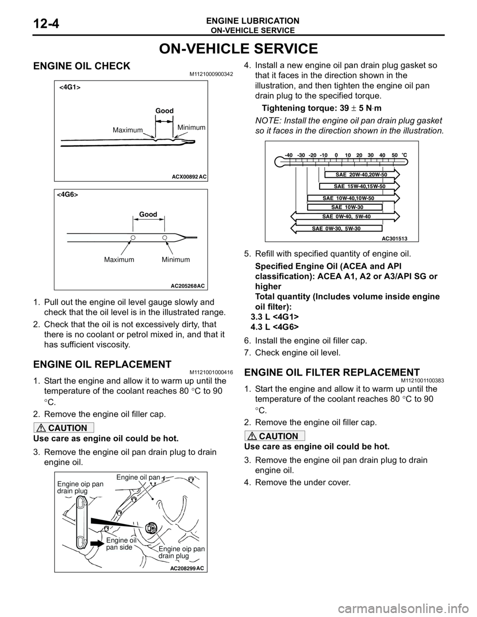
1. Pull out the engine oil level gauge slowly and
check that the oil level is in the illustrated range.
2. Check that the oil is not excessively dirty, that
there is no coolant or petrol mixed in, and that it
has sufficient viscosity.
ENGINE OIL REPLACEMENTM1121001000416
1. Start the engine and allow it to warm up until the
temperature of the coolant reaches 80 °C to 90
°C.
2. Remove the engine oil filler cap.
CAUTION
Use care as engine oil could be hot.
3. Remove the engine oil pan drain plug to drain
engine oil.4. Install a new engine oil pan drain plug gasket so
that it faces in the direction shown in the
illustration, and then tighten the engine oil pan
drain plug to the specified torque.
Tightening torque: 39 ± 5 N⋅m
NOTE: Install the engine oil pan drain plug gasket
so it faces in the direction shown in the illustration.
5. Refill with specified quantity of engine oil.
Specified Engine Oil (ACEA and API
classification): ACEA A1, A2 or A3/API SG or
higher
Total quantity (Includes volume inside engine
oil filter):
3.3 L <4G1>
4.3 L <4G6>
6. Install the engine oil filler cap.
7. Check engine oil level.
ENGINE OIL FILTER REPLACEMENTM1121001100383
1. Start the engine and allow it to warm up until the
temperature of the coolant reaches 80 °C to 90
°C.
2. Remove the engine oil filler cap.
CAUTION
Use care as engine oil could be hot.
3. Remove the engine oil pan drain plug to drain
engine oil.
4. Remove the under cover.
ACX00892 AC
Good
MaximumMinimum
<4G1>
AC205268
Maximum MinimumGood
AC
<4G6>
AC208299
Engine oil pan
AC
Engine oip pan
drain plug
Engine oip pan
drain plug
Engine oil
pan side
AC301513
Page 36 of 788
ON-VEHICLE SERVICE
ENGINE COOLING14-22
ON-VEHICLE SERVICE
ENGINE COOLANT LEAK CHECKM1141001000300
WARNING
When pressure testing the cooling system,
slowly release cooling system pressure to
avoid getting burned by hot coolant.
CAUTION
•Be sure to completely clean away any
moisture from the places checked.
•When the tester is taken out, be careful not to
spill any coolant.
•Be careful when installing and removing the
tester and when testing not to deform the
filler neck of the radiator.
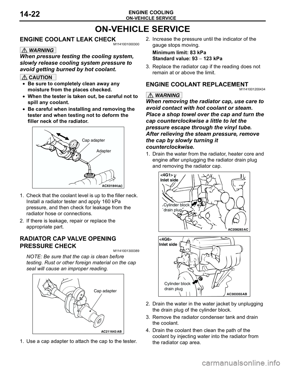
1. Check that the coolant level is up to the filler neck.
Install a radiator tester and apply 160 kPa
pressure, and then check for leakage from the
radiator hose or connections.
2. If there is leakage, repair or replace the
appropriate part.
RADIATOR CAP VALVE OPENING
PRESSURE CHECK
M1141001300389
NOTE: Be sure that the cap is clean before
testing. Rust or other foreign material on the cap
seal will cause an improper reading.
1. Use a cap adapter to attach the cap to the tester.2. Increase the pressure until the indicator of the
gauge stops moving.
Minimum limit: 83 kPa
Standard value: 93 − 123 kPa
3. Replace the radiator cap if the reading does not
remain at or above the limit.
ENGINE COOLANT REPLACEMENTM1141001200434
WARNING
When removing the radiator cap, use care to
avoid contact with hot coolant or steam.
Place a shop towel over the cap and turn the
cap counterclockwise a little to let the
pressure escape through the vinyl tube.
After relieving the steam pressure, remove
the cap by slowly turning it
counterclockwise.
1. Drain the water from the radiator, heater core and
engine after unplugging the radiator drain plug
and removing the radiator cap.
2. Drain the water in the water jacket by unplugging
the drain plug of the cylinder block.
3. Remove the radiator condenser tank and drain
the coolant.
4. Drain the coolant then clean the path of the
coolant by injecting water into the radiator from
the radiator cap area.
ACX01844
Cap adapter
Adapter
AC
AC211643AB
Cap adapter
AC208283AC
Cylinder block
drain plug
<4G1>
Inlet side
AC303355
<4G6>
Inlet side
Cylinder block
drain plug
AB
Page 37 of 788
ON-VEHICLE SERVICE
ENGINE COOLING14-23
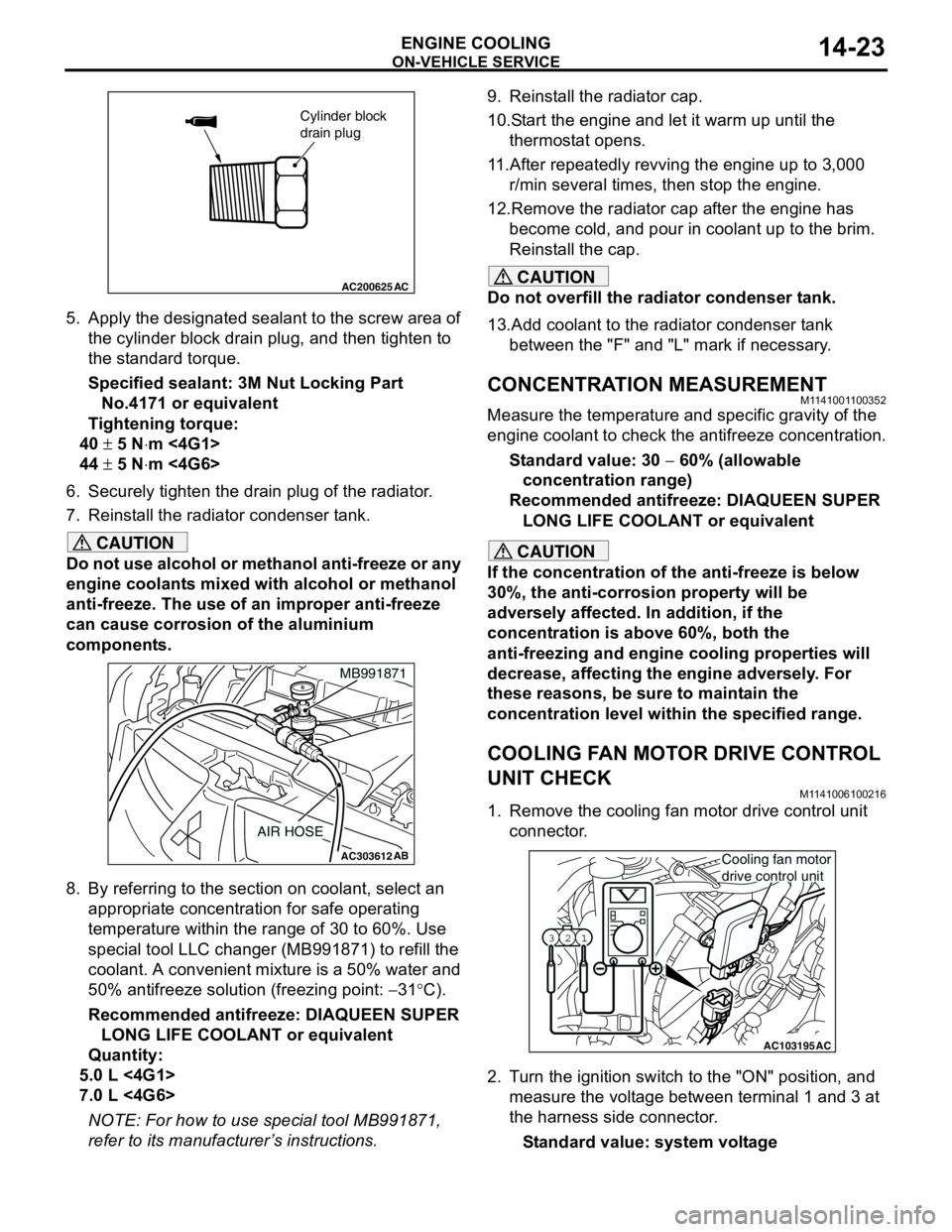
5. Apply the designated sealant to the screw area of
the cylinder block drain plug, and then tighten to
the standard torque.
Specified sealant: 3M Nut Locking Part
No.4171 or equivalent
Tightening torque:
40 ± 5 N⋅m <4G1>
44 ± 5 N⋅m <4G6>
6. Securely tighten the drain plug of the radiator.
7. Reinstall the radiator condenser tank.
CAUTION
Do not use alcohol or methanol anti-freeze or any
engine coolants mixed with alcohol or methanol
anti-freeze. The use of an improper anti-freeze
can cause corrosion of the aluminium
components.
8. By referring to the section on coolant, select an
appropriate concentration for safe operating
temperature within the range of 30 to 60%. Use
special tool LLC changer (MB991871) to refill the
coolant. A convenient mixture is a 50% water and
50% antifreeze solution (freezing point: −31°C).
Recommended antifreeze: DIAQUEEN SUPER
LONG LIFE COOLANT or equivalent
Quantity:
5.0 L <4G1>
7.0 L <4G6>
NOTE: For how to use special tool MB991871,
refer to its manufacturer’s instructions.9. Reinstall the radiator cap.
10.Start the engine and let it warm up until the
thermostat opens.
11.After repeatedly revving the engine up to 3,000
r/min several times, then stop the engine.
12.Remove the radiator cap after the engine has
become cold, and pour in coolant up to the brim.
Reinstall the cap.
CAUTION
Do not overfill the radiator condenser tank.
13.Add coolant to the radiator condenser tank
between the "F" and "L" mark if necessary.
CONCENTRATION MEASUREMENTM1141001100352
Measure the temperature and specific gravity of the
engine coolant to check the antifreeze concentration.
Standard value: 30 − 60% (allowable
concentration range)
Recommended antifreeze: DIAQUEEN SUPER
LONG LIFE COOLANT or equivalent
CAUTION
If the concentration of the anti-freeze is below
30%, the anti-corrosion property will be
adversely affected. In addition, if the
concentration is above 60%, both the
anti-freezing and engine cooling properties will
decrease, affecting the engine adversely. For
these reasons, be sure to maintain the
concentration level within the specified range.
COOLING FAN MOTOR DRIVE CONTROL
UNIT CHECK
M1141006100216
1. Remove the cooling fan motor drive control unit
connector.
2. Turn the ignition switch to the "ON" position, and
measure the voltage between terminal 1 and 3 at
the harness side connector.
Standard value: system voltage
AC200625
Cylinder block
drain plug
AC
AC303612AB
MB991871
AIR HOSE
AC103195
Y1716AU
1 23
AC
Cooling fan motor
drive control unit
Page 58 of 788
INLET MANIFOLD
INTAKE AND EXHAUST15-6
REMOVAL AND INSTALLATION <4G6>M1151003001236
Pre-removal Operation
•Fuel Line Pressure Reduction (Refer to GROUP 13A -
On-vehicle Service P.13A-389).
•Engine Coolant Draining (Refer to GROUP 14 -
On-vehicle Service P.14-22).
•Strut Tower Bar Removal (Refer to GROUP 42 P.42-9).
•Throttle Body Assembly Removal (Refer to GROUP 13B
P.13B-336).
•Fuel Delivery Pipe and Fuel Injector Assembly Removal
(Refer to GROUP 13B P.13B-334).Post-installation Operation
•Fuel Delivery Pipe and Fuel Injector Assembly Installation
(Refer to GROUP 13B P.13B-334).
•Throttle Body Assembly Installation (Refer to GROUP
13B P.13B-336).
•Strut Tower Bar Installation (Refer to GROUP 42 P.42-9).
•Engine Coolant Supplying (Refer to GROUP 14 -
On-vehicle Service P.14-22).
•Accelerator Cable Adjustment (Refer to GROUP 17 -
On-vehicle Service P.17-2).
•Fuel Leak Check
AC303657
9.0 ± 1.0 N·m11 ± 1 N·m
20 ± 2 N·m
31 ± 3 N·m 36 ± 6 N·m
20 ± 2 N·m
20 ± 2 N·m
36 ± 6 N·m
36 ± 6 N·m
11
9 10 212
N1413N
AB
5.0 ± 1.0 N·m
3
1
11 ± 1 N·m
4
N
13 ± 1 N·m
5
6
(Engine oil)
7
8
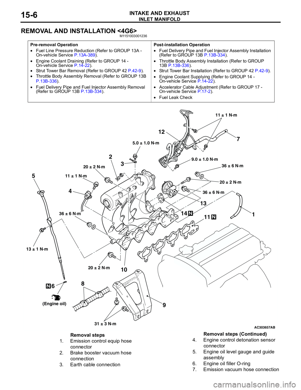
Removal steps
1. Emission control equip hose
connector
2. Brake booster vacuum hose
connection
3. Earth cable connection4. Engine control detonation sensor
connector
5. Engine oil level gauge and guide
assembly
6. Engine oil filler O-ring
7. Emission vacuum hose connectionRemoval steps (Continued)
Page 117 of 788
EMISSION CONTROL
ENGINE AND EMISSION CONTROL17-9
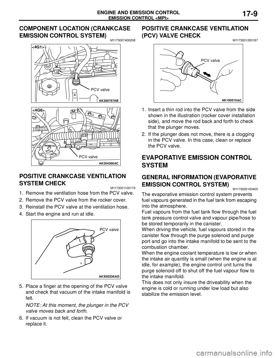
COMPONENT LOCATION (CRANKCASE
EMISSION CONTROL SYSTEM)
M1173007400208
POSITIVE CRANKCASE VENTILATION
SYSTEM CHECK
M1173001100179
1. Remove the ventilation hose from the PCV valve.
2. Remove the PCV valve from the rocker cover.
3. Reinstall the PCV valve at the ventilation hose.
4. Start the engine and run at idle.
5. Place a finger at the opening of the PCV valve
and check that vacuum of the intake manifold is
felt.
NOTE: At this moment, the plunger in the PCV
valve moves back and forth.
6. If vacuum is not felt, clean the PCV valve or
replace it.
POSITIVE CRANKCASE VENTILATION
(PCV) VALVE CHECK
M1173001200187
1. Insert a thin rod into the PCV valve from the side
shown in the illustration (rocker cover installation
side), and move the rod back and forth to check
that the plunger moves.
2. If the plunger does not move, there is a clogging
in the PCV valve. In this case, clean or replace
the PCV valve.
EVAPORATIVE EMISSION CONTROL
SYSTEM
GENERAL INFORMATION (EVAPORATIVE
EMISSION CONTROL SYSTEM)
M1173005100405
The evaporative emission control system prevents
fuel vapours generated in the fuel tank from escaping
into the atmosphere.
Fuel vapours from the fuel tank flow through the fuel
tank pressure control valve and vapour pipe/hose to
be stored temporarily in the canister.
When driving the vehicle, fuel vapours stored in the
canister flow through the purge solenoid and purge
port and go into the intake manifold to be sent to the
combustion chamber.
When the engine coolant temperature is low or when
the intake air quantity is small (when the engine is at
idle, for example), the engine control unit turns the
purge solenoid off to shut off the fuel vapour flow to
the intake manifold.
This does not only insure the driveability when the
engine is cold or running under low load but also
stabilize the emission level.
AK300767
<4G1>
AB
PCV valve
AK204366
<4G6>
AC
PCV valve
AKX00336
PCV valve
AD
AK100010
PCV valve
AC
Page 121 of 788
EMISSION CONTROL
ENGINE AND EMISSION CONTROL17-13
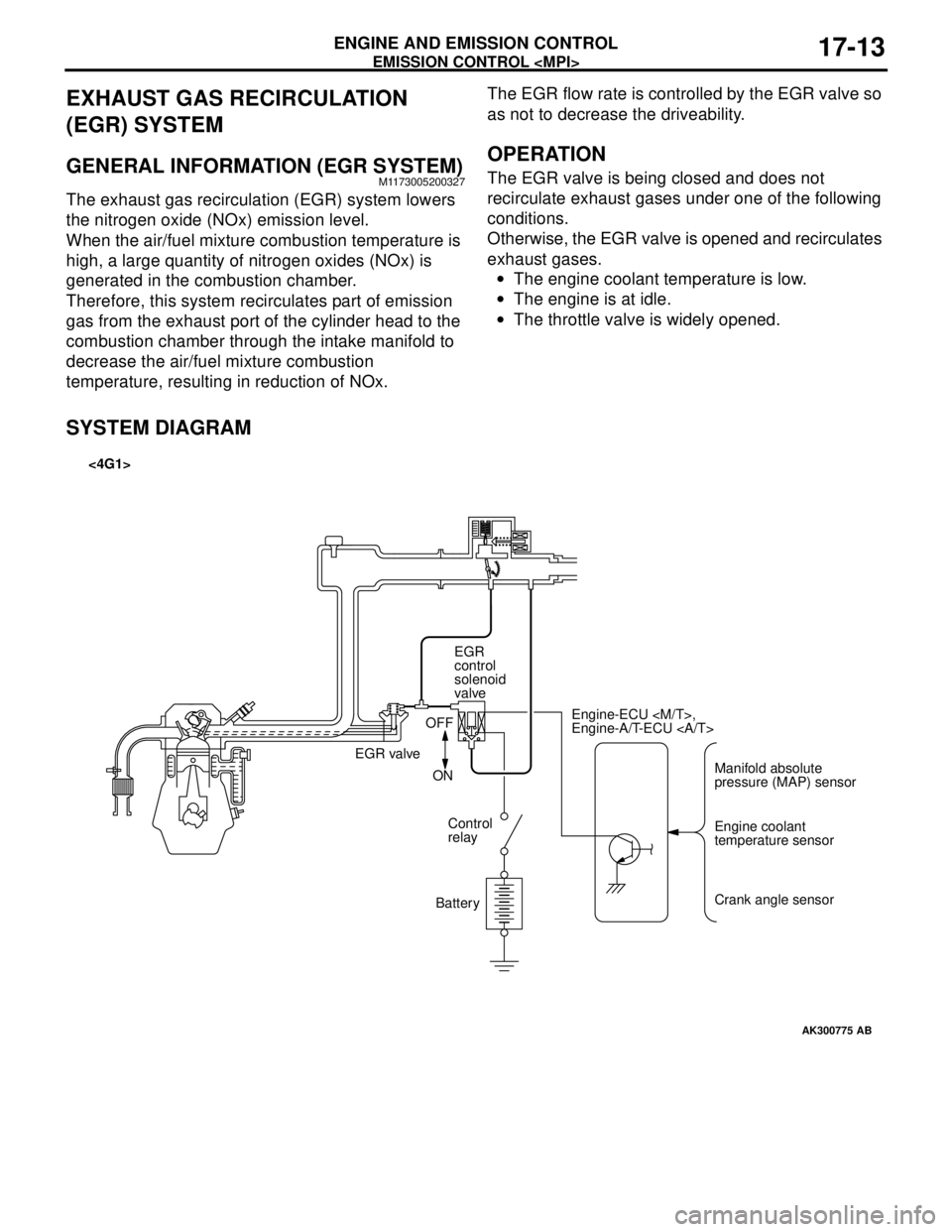
EXHAUST GAS RECIRCULATION
(EGR) SYSTEM
GENERAL INFORMATION (EGR SYSTEM)M1173005200327
The exhaust gas recirculation (EGR) system lowers
the nitrogen oxide (NOx) emission level.
When the air/fuel mixture combustion temperature is
high, a large quantity of nitrogen oxides (NOx) is
generated in the combustion chamber.
Therefore, this system recirculates part of emission
gas from the exhaust port of the cylinder head to the
combustion chamber through the intake manifold to
decrease the air/fuel mixture combustion
temperature, resulting in reduction of NOx.The EGR flow rate is controlled by the EGR valve so
as not to decrease the driveability.
OPERATION
The EGR valve is being closed and does not
recirculate exhaust gases under one of the following
conditions.
Otherwise, the EGR valve is opened and recirculates
exhaust gases.
•The engine coolant temperature is low.
•The engine is at idle.
•The throttle valve is widely opened.
SYSTEM DIAGRAM
AK300775
Manifold absolute
pressure (MAP) sensor Engine-ECU
Engine-A/T-ECU
Engine coolant
temperature sensor
Crank angle sensor EGR
control
solenoid
valve
EGR valveOFF
ON
Control
relay
Battery
AB
<4G1>
Page 390 of 788
54A-2
COMBINATION METER
ASSEMBLY . . . . . . . . . . . . . . . .
54A-29
SERVICE SPECIFICATIONS. . . . .
54A-29
SEALANT. . . . . . . . . . . . . . . . . . . .54A-29
SPECIAL TOOLS. . . . . . . . . . . . . .54A-29
TROUBLESHOOTING . . . . . . . . . .54A-31
SYMPTOM CHART . . . . . . . . . . . . . . . . 54A-31
SYMPTOM PROCEDURES . . . . . .54A-32
ON-VEHICLE SERVICE. . . . . . . . .54A-60
SPEEDOMETER CHECK . . . . . . . . . . . 54A-60
TACHOMETER CHECK . . . . . . . . . . . . 54A-60
FUEL TANK GAUGE UNIT CHECK . . . 54A-61
ENGINE COOLANT TEMPERATURE GAUGE
UNIT CHECK . . . . . . . . . . . . . . . . . . . . . 54A-61
COMBINATION METER ASSEMBLY54A-63
REMOVAL AND INSTALLATION . . . . . 54A-63
INSPECTION . . . . . . . . . . . . . . . . . . . . . 54A-64
DISASSEMBLY AND REASSEMBLY . . 54A-65
HEADLAMP . . . . . . . . . . . . . . . .54A-66
SERVICE SPECIFICATIONS. . . . .
54A-66
TROUBLESHOOTING . . . . . . . . . .54A-66
ON-VEHICLE SERVICE. . . . . . . . .54A-66
HEADLAMP AIMING . . . . . . . . . . . . . . . 54A-66
LUMINOUS INTENSITY
MEASUREMENT . . . . . . . . . . . . . . . . . . 54A-67
BULB REPLACEMENT . . . . . . . . . . . . . 54A-68
HEADLAMP . . . . . . . . . . . . . . . . . .54A-69
REMOVAL AND INSTALLATION . . . . . 54A-69
HEADLAMP LEVELING SWITCH .54A-70
REMOVAL AND INSTALLATION . . . . . 54A-70
INSPECTION . . . . . . . . . . . . . . . . . . . . . 54A-70
FOG LAMP . . . . . . . . . . . . . . . . 54A-71
SERVICE SPECIFICATION . . . . . .
54A-71
SPECIAL TOOL . . . . . . . . . . . . . . .54A-71
TROUBLESHOOTING . . . . . . . . . .54A-71
ON-VEHICLE SERVICE . . . . . . . . .54A-71
FRONT FOG LAMP AIMING CHECK . . 54A-71
FOG LAMP . . . . . . . . . . . . . . . . . . .54A-73
REMOVAL AND INSTALLATION . . . . . . 54A-73
FOG LAMP SWITCH . . . . . . . . . . .54A-74
REMOVAL AND INSTALLATION . . . . . . 54A-74
INSPECTION . . . . . . . . . . . . . . . . . . . . . 54A-74
REAR FOG LAMP . . . . . . . . . . 54A-75
TROUBLESHOOTING . . . . . . . . . .
54A-75
SPECIAL TOOL . . . . . . . . . . . . . . .54A-75
REAR FOG LAMP . . . . . . . . . . . . .54A-76
REMOVAL AND INSTALLATION . . . . . . 54A-76
REAR FOG LAMP SWITCH . . . . . .54A-76
REMOVAL AND INSTALATION . . . . . . . 54A-76
INSPECTION . . . . . . . . . . . . . . . . . . . . . 54A-76
SIDE TURN-SIGNAL LAMP. . . 54A-77
SPECIAL TOOL . . . . . . . . . . . . . . .
54A-77
SIDE TURN-SIGNAL LAMP . . . . . .54A-77
REMOVAL AND INSTALLATION . . . . . . 54A-77
ROOM LAMP . . . . . . . . . . . . . . 54A-78
TROUBLESHOOTING . . . . . . . . . . . . . . 54A-78
Continued on next page
Page 725 of 788
METER AND GAUGE
CIRCUIT DIAGRAMS90-87
METER AND GAUGE
M1901003501072
RELAY
BOXBATTERYFRONT-ECU
(TAIL LAMP RELAY)
TAIL LAMP,
POSITION LAMP,
LICENCE PLATE
LAMP AND LIGHTING
MONITOR BUZZER
ODO/TRIP
ENGINE
SPEED
DETECTION
CONNECTOR ENGINE-
ECU
ENGINE-
A/T-ECU
DIAGNOSIS
CONNECTOR
·TAIL LAMP, POSITION LAMP,
LICENCE PLATE LAMP AND
LIGHTING MONITOR BUZZER
·WINDSHIELD WIPER
AND WASHER ·FRONT FOG LAMP
·HEADLAMP
·HEADLAMP
LEVELLING SYSTEM
·REAR FOG LAMP
IGNITION
SWITCH (IG1)
COMBINATION
METER
CONTROL CIRCUIT
ENGINE
COOLANT
TEMPERATURE
GAUGE UNITFUEL
GAUGE
UNIT
NOTE
: SEDAN
: WAGON
: M/T
: A/T
FRONT SIDE : EXCEPT 4G6
: 4G6
Page 727 of 788
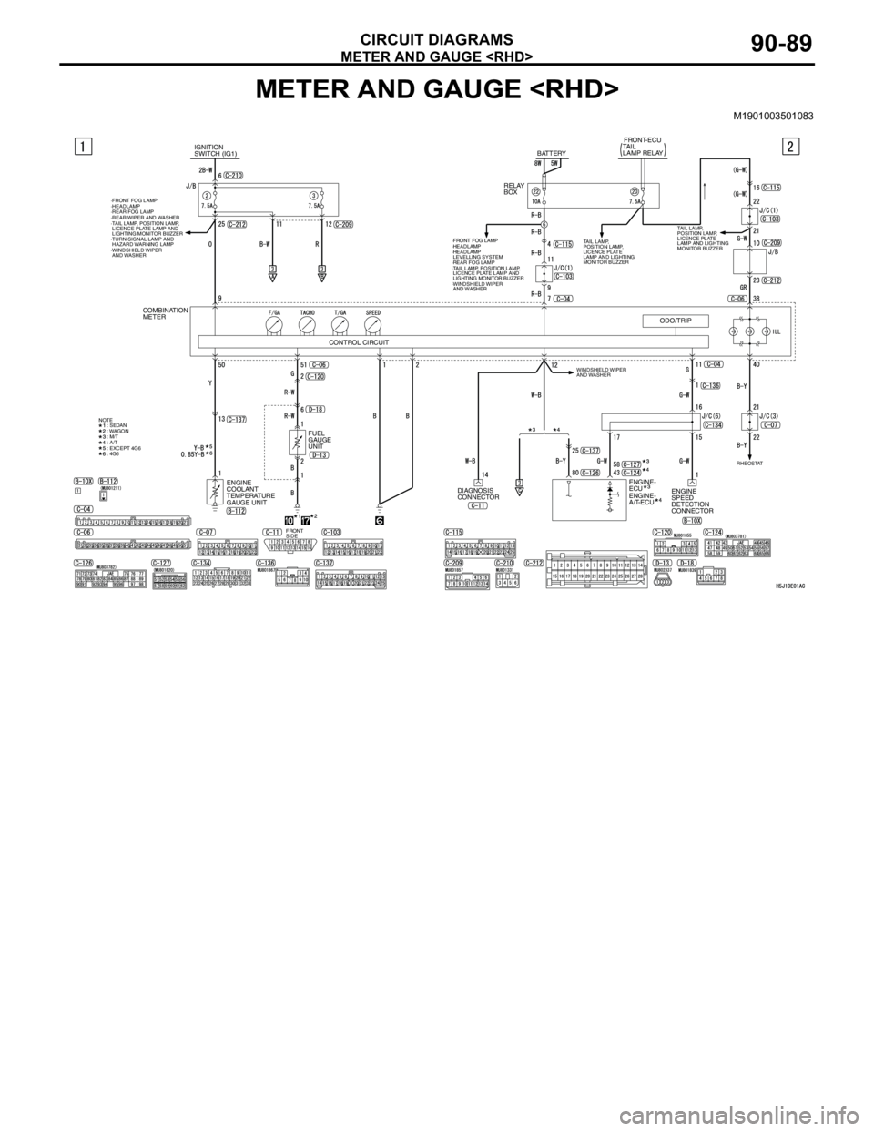
METER AND GAUGE
CIRCUIT DIAGRAMS90-89
METER AND GAUGE
M1901003501083
DIAGNOSIS
CONNECTOR
RELAY
BOXBATTERYFRONT-ECU
TAIL
LAMP RELAY
TAIL LAMP,
POSITION LAMP,
LICENCE PLATE
LAMP AND LIGHTING
MONITOR BUZZERTAIL LAMP,
POSITION LAMP,
LICENCE PLATE
LAMP AND LIGHTING
MONITOR BUZZER
ODO/TRIP
ENGINE
SPEED
DETECTION
CONNECTOR ENGINE-
ECU
ENGINE-
A/T-ECU
RHEOSTAT ·TAIL LAMP, POSITION LAMP,
LICENCE PLATE LAMP AND
LIGHTING MONITOR BUZZER
·WINDSHIELD WIPER
AND WASHER
WINDSHIELD WIPER
AND WASHER ·FRONT FOG LAMP
·HEADLAMP
·HEADLAMP
LEVELLING SYSTEM
·REAR FOG LAMP
IGNITION
SWITCH (IG1)
COMBINATION
METER
CONTROL CIRCUIT
ENGINE
COOLANT
TEMPERATURE
GAUGE UNITFUEL
GAUGE
UNIT
NOTE
: SEDAN
: WAGON
: M/T
: A/T
: EXCEPT 4G6
: 4G6
FRONT
SIDE ·TAIL LAMP, POSITION LAMP,
LICENCE PLATE LAMP AND
LIGHTING MONITOR BUZZER
·TURN-SIGNAL LAMP AND
HAZARD WARNING LAMP
·WINDSHIELD WIPER
AND WASHER ·FRONT FOG LAMP
·HEADLAMP
·REAR FOG LAMP
·REAR WIPER AND WASHER