steering MITSUBISHI LANCER 2005 Service Manual
[x] Cancel search | Manufacturer: MITSUBISHI, Model Year: 2005, Model line: LANCER, Model: MITSUBISHI LANCER 2005Pages: 788, PDF Size: 45.98 MB
Page 259 of 788
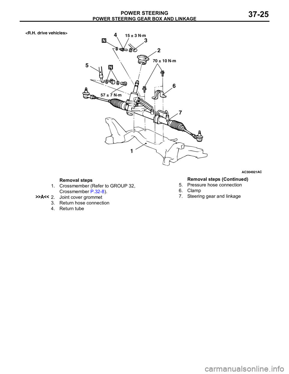
POWER STEERING GEAR BOX AND LINKAGE
POWER STEERING37-25
AC304921AC
57 ± 7 N·m15 ± 3 N·m
70 ± 10 N·m
3
52 4
1
6
7
Removal steps
1. Crossmember (Refer to GROUP 32,
Crossmember P.32-8).
>>A<<2. Joint cover grommet
3. Return hose connection
4. Return tube5. Pressure hose connection
6. Clamp
7. Steering gear and linkageRemoval steps (Continued)
Page 260 of 788
POWER STEERING GEAR BOX AND LINKAGE
POWER STEERING37-26
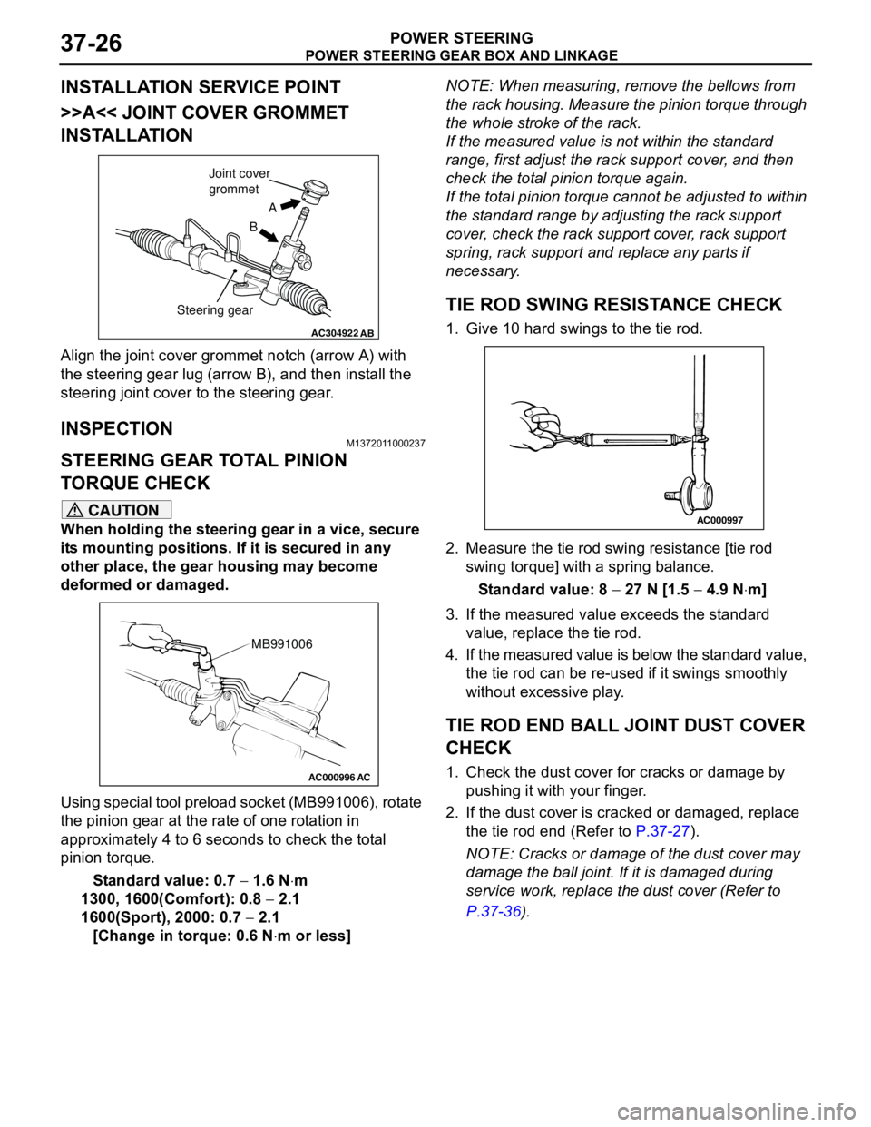
INSTALLATION SERVICE POINT
>>A<< JOINT COVER GROMMET
INSTALLATION
Align the joint cover grommet notch (arrow A) with
the steering gear lug (arrow B), and then install the
steering joint cover to the steering gear.
INSPECTIONM1372011000237
STEERING GEAR TOTAL PINION
TORQUE CHECK
CAUTION
When holding the steering gear in a vice, secure
its mounting positions. If it is secured in any
other place, the gear housing may become
deformed or damaged.
Using special tool preload socket (MB991006), rotate
the pinion gear at the rate of one rotation in
approximately 4 to 6 seconds to check the total
pinion torque.
Standard value: 0.7 − 1.6 N⋅m
1300, 1600(Comfort): 0.8 − 2.1
1600(Sport), 2000: 0.7 − 2.1
[Change in torque: 0.6 N⋅m or less]NOTE: When measuring, remove the bellows from
the rack housing. Measure the pinion torque through
the whole stroke of the rack.
If the measured value is not within the standard
range, first adjust the rack support cover, and then
check the total pinion torque again.
If the total pinion torque cannot be adjusted to within
the standard range by adjusting the rack support
cover, check the rack support cover, rack support
spring, rack support and replace any parts if
necessary.
TIE ROD SWING RESISTANCE CHECK
1. Give 10 hard swings to the tie rod.
2. Measure the tie rod swing resistance [tie rod
swing torque] with a spring balance.
Standard value: 8 − 27 N [1.5 − 4.9 N⋅m]
3. If the measured value exceeds the standard
value, replace the tie rod.
4. If the measured value is below the standard value,
the tie rod can be re-used if it swings smoothly
without excessive play.
TIE ROD END BALL JOINT DUST COVER
CHECK
1. Check the dust cover for cracks or damage by
pushing it with your finger.
2. If the dust cover is cracked or damaged, replace
the tie rod end (Refer to P.37-27).
NOTE: Cracks or damage of the dust cover may
damage the ball joint. If it is damaged during
service work, replace the dust cover (Refer to
P.37-36).
AC304922AB
A
B Joint cover
grommet
Steering gear
AC000996 AC
MB991006
AC000997
Page 261 of 788
POWER STEERING GEAR BOX AND LINKAGE
POWER STEERING37-27
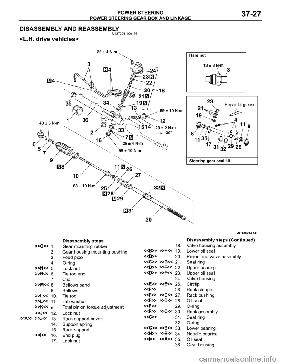
DISASSEMBLY AND REASSEMBLYM1372011100193
AC100244AE
3
13 ± 3 N·m
Steering gear seal kit Flare nut
Repair kit grease
23
21
19
4
11
8
28 29
32 31 17 35
11 8
22 ± 4 N·m
59 ± 10 N·m
23 ± 2 N·m
-30˚
12
14
15
33
17
59 ± 10 N·m25 ± 4 N·m
18 24
23
20
19
2122
13 344
4
3
35
136
2
16
30 31
32
27
29 28
2526 1188 ± 10 N·m
10 8
9 7 5 6
40 ± 5 N·m
Disassembly steps
>>O<<1. Gear mounting rubber
2. Gear housing mounting bushing
3. Feed pipe
4. O-ring
>>N<<5. Lock nut
>>N<<6. Tie rod end
7. Clip
>>M<<8. Bellows band
9. Bellows
>>L<<10. Tie rod
>>L<<11. Tab washer
>>K<<•Total pinion torque adjustment
>>J<<12. Lock nut
<> >>J<<13. Rack support cover
14. Support spring
15. Rack support
>>I<<16. End plug
17. Lock nut18. Valve housing assembly
<> >>H<<19. Lower oil seal
<>20. Pinion and valve assembly
<
<
<
24. Valve housing
<
<
<
<
<
<
<
32. O-ring
<
<
<> >>A<<35. Oil seal
36. Gear housingDisassembly steps (Continued)
Page 262 of 788
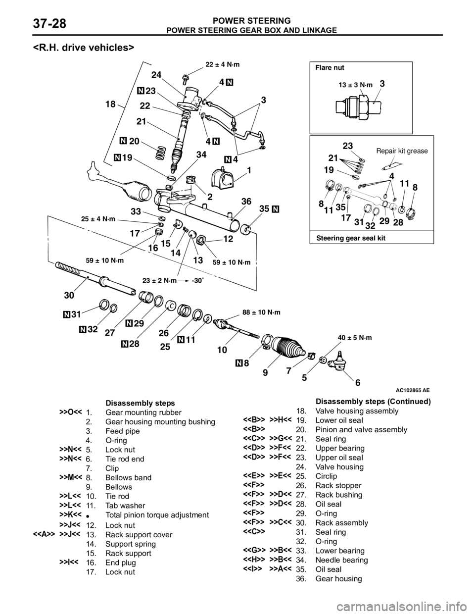
POWER STEERING GEAR BOX AND LINKAGE
POWER STEERING37-28
AC102865
3
23
21
19
4
11
8
8
1135
17
31
3229
28
6 5 7
9 8 10 11
25 26
2829
27 32 31 3012
13 14 15
16 173335 361 4
2 3444
3 24
23
22
21
20
19
18
AE
Steering gear seal kit Flare nut
Repair kit grease 22 ± 4 N·m
59 ± 10 N·m 25 ± 4 N·m
88 ± 10 N·m
40 ± 5 N·m 59 ± 10 N·m13 ± 3 N·m
23 ± 2 N·m -30˚
Disassembly steps
>>O<<1. Gear mounting rubber
2. Gear housing mounting bushing
3. Feed pipe
4. O-ring
>>N<<5. Lock nut
>>N<<6. Tie rod end
7. Clip
>>M<<8. Bellows band
9. Bellows
>>L<<10. Tie rod
>>L<<11. Tab washer
>>K<<•Total pinion torque adjustment
>>J<<12. Lock nut
<> >>J<<13. Rack support cover
14. Support spring
15. Rack support
>>I<<16. End plug
17. Lock nut18. Valve housing assembly
<> >>H<<19. Lower oil seal
<>20. Pinion and valve assembly
<
<
<
24. Valve housing
<
<
<
<
<
<
<
32. O-ring
<
<
<> >>A<<35. Oil seal
36. Gear housingDisassembly steps (Continued)
Page 263 of 788
POWER STEERING GEAR BOX AND LINKAGE
POWER STEERING37-29
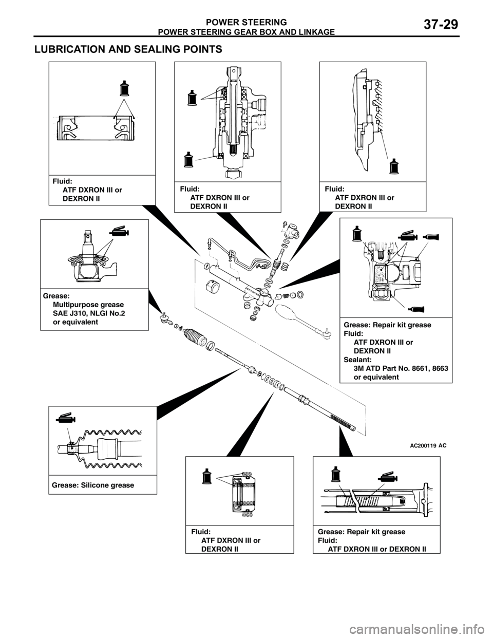
LUBRICATION AND SEALING POINTS
AC200119AC
Grease: Silicone greaseFluid:
ATF DXRON III or
DEXRON II
Grease: Repair kit grease
Fluid:
ATF DXRON III or
DEXRON II
Sealant:
3M ATD Part No. 8661, 8663
or equivalent Grease:
Multipurpose grease
SAE J310, NLGI No.2
or equivalent
Fluid:
ATF DXRON III or
DEXRON IIFluid:
ATF DXRON III or
DEXRON II
Fluid:
ATF DXRON III or
DEXRON IIGrease: Repair kit grease
Fluid:
ATF DXRON III or DEXRON II
Page 264 of 788
POWER STEERING GEAR BOX AND LINKAGE
POWER STEERING37-30
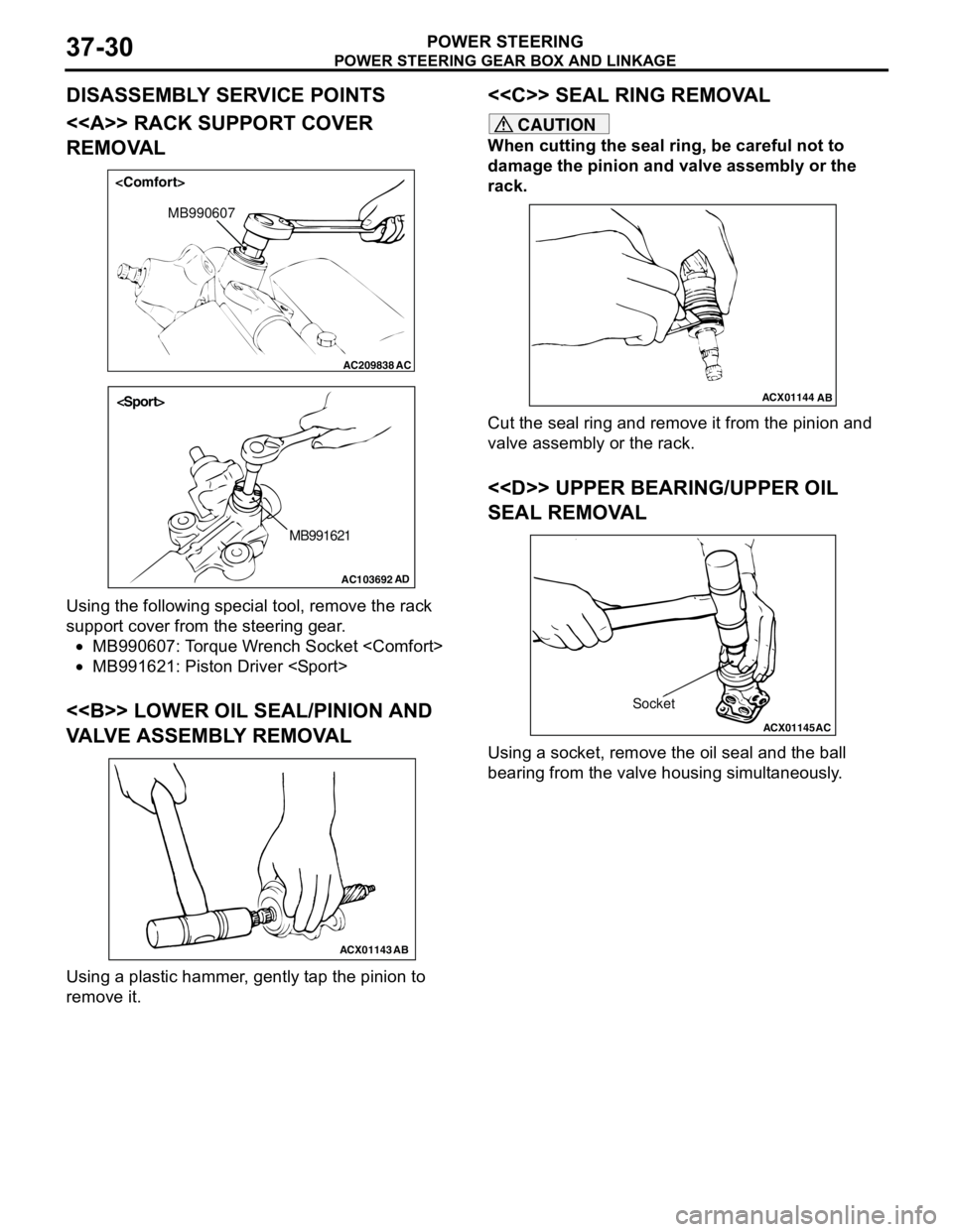
DISASSEMBLY SERVICE POINTS
<> RACK SUPPORT COVER
REMOVAL
Using the following special tool, remove the rack
support cover from the steering gear.
•MB990607: Torque Wrench Socket
•MB991621: Piston Driver
<> LOWER OIL SEAL/PINION AND
VALVE ASSEMBLY REMOVAL
Using a plastic hammer, gently tap the pinion to
remove it.
<
CAUTION
When cutting the seal ring, be careful not to
damage the pinion and valve assembly or the
rack.
Cut the seal ring and remove it from the pinion and
valve assembly or the rack.
<
SEAL REMOVAL
Using a socket, remove the oil seal and the ball
bearing from the valve housing simultaneously.
AC209838
MB990607
AC
AC103692AD
MB991621
ACX01143
AB
ACX01144
AB
ACX01145
AC
Socket
Page 265 of 788
POWER STEERING GEAR BOX AND LINKAGE
POWER STEERING37-31
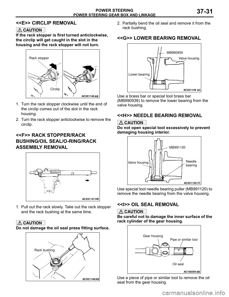
<
CAUTION
If the rack stopper is first turned anticlockwise,
the circlip will get caught in the slot in the
housing and the rack stopper will not turn.
1. Turn the rack stopper clockwise until the end of
the circlip comes out of the slot in the rack
housing.
2. Turn the rack stopper anticlockwise to remove the
circlip.
<
BUSHING/OIL SEAL/O-RING/RACK
ASSEMBLY REMOVAL
1. Pull out the rack slowly. Take out the rack stopper
and the rack bushing at the same time.
CAUTION
Do not damage the oil seal press fitting surface.2. Partially bend the oil seal and remove it from the
rack bushing.
<
Use a brass bar or special tool brass bar
(MB990939) to remove the lower bearing from the
valve housing.
<
CAUTION
Do not open special tool excessively to prevent
damaging housing interior.
Use special tool needle bearing puller (MB991120) to
remove the needle bearing from the valve housing.
<> OIL SEAL REMOVAL
CAUTION
Be careful not to damage the inner surface of the
rack cylinder of the gear housing.
Use a piece of pipe or similar tool to remove the oil
seal from the gear housing.
ACX01146
AB
Circlip Rack stopper
ACX01147AB
ACX01148AB
Rack bushing
ACX01149
MB990939
Lower bearing
AC
Valve housing
ACX01150AB
Valve housingMB991120Needle
bearing
AC100259
Oil seal Pipe or similar tool Gear housing
AB
Page 266 of 788
POWER STEERING GEAR BOX AND LINKAGE
POWER STEERING37-32
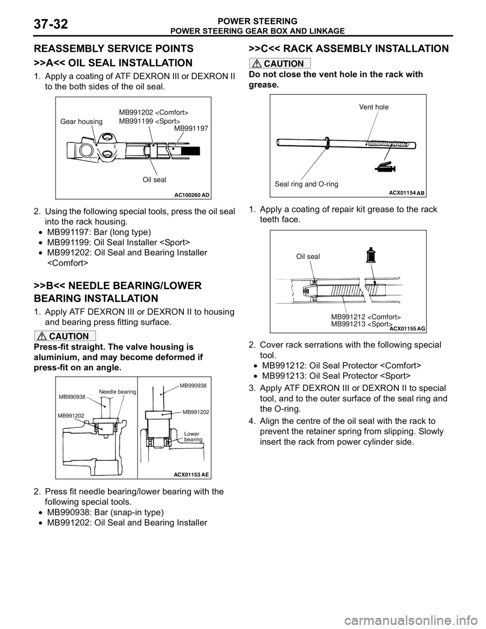
REASSEMBLY SERVICE POINTS
>>A<< OIL SEAL INSTALLATION
1. Apply a coating of ATF DEXRON III or DEXRON II
to the both sides of the oil seal.
2. Using the following special tools, press the oil seal
into the rack housing.
•MB991197: Bar (long type)
•MB991199: Oil Seal Installer
•MB991202: Oil Seal and Bearing Installer
>>B<< NEEDLE BEARING/LOWER
BEARING INSTALLATION
1. Apply ATF DEXRON III or DEXRON II to housing
and bearing press fitting surface.
CAUTION
Press-fit straight. The valve housing is
aluminium, and may become deformed if
press-fit on an angle.
2. Press fit needle bearing/lower bearing with the
following special tools.
•MB990938: Bar (snap-in type)
•MB991202: Oil Seal and Bearing Installer
>>C<< RACK ASSEMBLY INSTALLATION
CAUTION
Do not close the vent hole in the rack with
grease.
1. Apply a coating of repair kit grease to the rack
teeth face.
2. Cover rack serrations with the following special
tool.
•MB991212: Oil Seal Protector
•MB991213: Oil Seal Protector
3. Apply ATF DEXRON III or DEXRON II to special
tool, and to the outer surface of the seal ring and
the O-ring.
4. Align the centre of the oil seal with the rack to
prevent the retainer spring from slipping. Slowly
insert the rack from power cylinder side.
AC100260AD
MB991197
Oil seal MB991202
MB991199
Gear housing
ACX01153
Needle bearing
MB990938
MB991202MB991202
Lower
bearing
AE MB990938
ACX01154
AB
Seal ring and O-ringVent hole
ACX01155
MB991212
MB991213
AG
Oil seal
Page 267 of 788
POWER STEERING GEAR BOX AND LINKAGE
POWER STEERING37-33
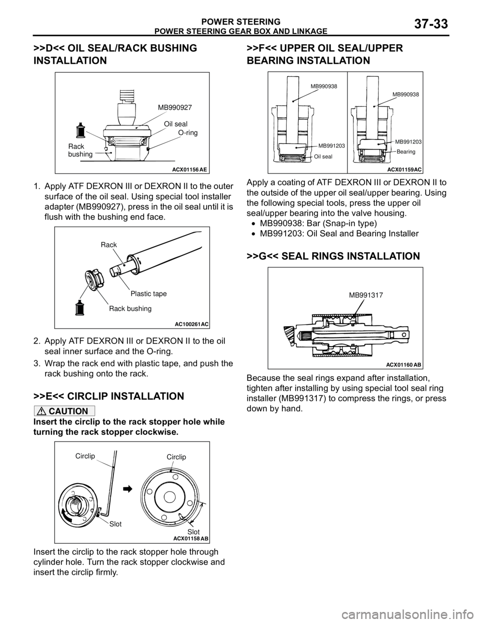
>>D<< OIL SEAL/RACK BUSHING
INSTALLATION
1. Apply ATF DEXRON III or DEXRON II to the outer
surface of the oil seal. Using special tool installer
adapter (MB990927), press in the oil seal until it is
flush with the bushing end face.
2. Apply ATF DEXRON III or DEXRON II to the oil
seal inner surface and the O-ring.
3. Wrap the rack end with plastic tape, and push the
rack bushing onto the rack.
>>E<< CIRCLIP INSTALLATION
CAUTION
Insert the circlip to the rack stopper hole while
turning the rack stopper clockwise.
Insert the circlip to the rack stopper hole through
cylinder hole. Turn the rack stopper clockwise and
insert the circlip firmly.
>>F<< UPPER OIL SEAL/UPPER
BEARING INSTALLATION
Apply a coating of ATF DEXRON III or DEXRON II to
the outside of the upper oil seal/upper bearing. Using
the following special tools, press the upper oil
seal/upper bearing into the valve housing.
•MB990938: Bar (Snap-in type)
•MB991203: Oil Seal and Bearing Installer
>>G<< SEAL RINGS INSTALLATION
Because the seal rings expand after installation,
tighten after installing by using special tool seal ring
installer (MB991317) to compress the rings, or press
down by hand.
ACX01156AE
Oil seal
O-ring MB990927
Rack
bushing
AC100261
AC
Rack
Plastic tape
Rack bushing
ACX01158
Circlip
Slot
AB
Circlip
Slot
ACX01159AC MB990938
MB991203
Oil seal
MB991203
Bearing MB990938
ACX01160AB
MB991317
Page 268 of 788
POWER STEERING GEAR BOX AND LINKAGE
POWER STEERING37-34
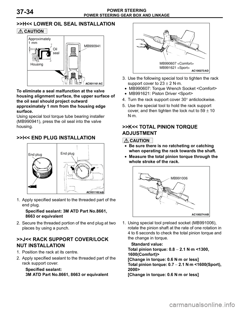
>>H<< LOWER OIL SEAL INSTALLATION
CAUTION
To eliminate a seal malfunction at the valve
housing alignment surface, the upper surface of
the oil seal should project outward
approximately 1 mm from the housing edge
surface.
Using special tool torque tube bearing installer
(MB990941), press the oil seal into the valve
housing.
>>I<< END PLUG INSTALLATION
1. Apply specified sealant to the threaded part of the
end plug.
Specified sealant: 3M ATD Part No.8661,
8663 or equivalent
2. Secure the threaded portion of the end plug at two
places by using a punch.
>>J<< RACK SUPPORT COVER/LOCK
NUT INSTALLATION
1. Position the rack at its centre.
2. Apply specified sealant to the threaded part of the
rack support cover.
Specified sealant:
3M ATD Part No.8661, 8663 or equivalent3. Use the following special tool to tighten the rack
support cover to 23 ± 2 N⋅m.
•MB990607: Torque Wrench Socket
•MB991621: Piston Driver
4. Turn the rack support cover 30° anticlockwise.
5. Use the special tool to hold the rack support
cover, and then tighten the lock nut to 59 ± 10
N⋅m.
>>K<< TOTAL PINION TORQUE
ADJUSTMENT
CAUTION
•Be sure there is no ratcheting or catching
when operating the rack towards the shaft.
•Measure the total pinion torque through the
whole stroke of the rack.
1. Using special tool preload socket (MB991006),
rotate the pinion shaft at the rate of one rotation in
4 to 6 seconds to check the total pinion torque and
the change in torque.
Standard value:
Total pinion torque: 0.8 − 2.1 N⋅m <1300,
1600(Comfort)>
[Change in torque: 0.6 N⋅m or less]
Total pinion torque: 0.7 − 2.1 N⋅m <1600(Sport),
2000>
[Change in torque: 0.6 N⋅m or less]
ACX01161
Housing
AC
Oil
seal
Approximately
1 mm
MB990941
ACX01162
AB
End plugEnd plug
AC100273
MB990607
MB991621
AD
AC100274 AB
MB991006