rear MITSUBISHI LANCER 2005 Repair Manual
[x] Cancel search | Manufacturer: MITSUBISHI, Model Year: 2005, Model line: LANCER, Model: MITSUBISHI LANCER 2005Pages: 788, PDF Size: 45.98 MB
Page 226 of 788
GENERAL INFORMATION
PARKING BRAKES36-2
GENERAL INFORMATION
M1361000100496
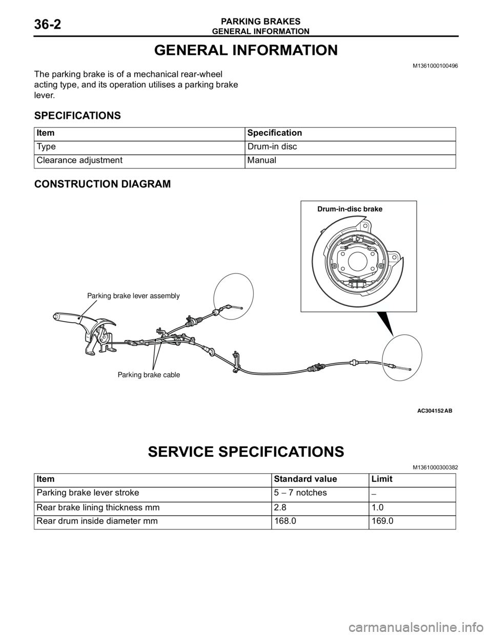
The parking brake is of a mechanical rear-wheel
acting type, and its operation utilises a parking brake
lever.
SPECIFICATIONS
CONSTRUCTION DIAGRAM
SERVICE SPECIFICATIONS
M1361000300382
Item Specification
Type Drum-in disc
Clearance adjustment Manual
AC211553
AC104333
AC304152
Parking brake lever assembly
Parking brake cable
AB
Drum-in-disc brake
Item Standard value Limit
Parking brake lever stroke 5 − 7 notches
−
Rear brake lining thickness mm 2.8 1.0
Rear drum inside diameter mm 168.0 169.0
Page 227 of 788
LUBRICANTS
PARKING BRAKES36-3
LUBRICANTS
M1361000400293
ON-VEHICLE SERVICE
PARKING BRAKE LEVER STROKE
CHECK AND ADJUSTMENT
M1361000900339
1. Pull the parking brake lever with a force of
approximately 200 N and count the number of
notches.
Standard value: 5 − 7 notches
2. If the parking brake lever stroke is not the
standard value, adjust as described below.
(1) Remove the rear console assembly (Refer to
GROUP 52A, Rear Floor Console P.52A-8).
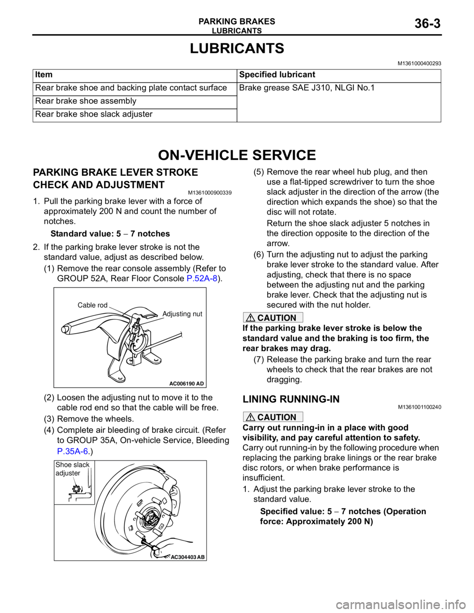
(2) Loosen the adjusting nut to move it to the
cable rod end so that the cable will be free.
(3) Remove the wheels.
(4) Complete air bleeding of brake circuit. (Refer
to GROUP 35A, On-vehicle Service, Bleeding
P.35A-6.)(5) Remove the rear wheel hub plug, and then
use a flat-tipped screwdriver to turn the shoe
slack adjuster in the direction of the arrow (the
direction which expands the shoe) so that the
disc will not rotate.
Return the shoe slack adjuster 5 notches in
the direction opposite to the direction of the
arrow.
(6) Turn the adjusting nut to adjust the parking
brake lever stroke to the standard value. After
adjusting, check that there is no space
between the adjusting nut and the parking
brake lever. Check that the adjusting nut is
secured with the nut holder.
CAUTION
If the parking brake lever stroke is below the
standard value and the braking is too firm, the
rear brakes may drag.
(7) Release the parking brake and turn the rear
wheels to check that the rear brakes are not
dragging.
LINING RUNNING-INM1361001100240
CAUTION
Carry out running-in in a place with good
visibility, and pay careful attention to safety.
Carry out running-in by the following procedure when
replacing the parking brake linings or the rear brake
disc rotors, or when brake performance is
insufficient.
1. Adjust the parking brake lever stroke to the
standard value.
Specified value: 5 − 7 notches (Operation
force: Approximately 200 N) Item Specified lubricant
Rear brake shoe and backing plate contact surface Brake grease SAE J310, NLGI No.1
Rear brake shoe assembly
Rear brake shoe slack adjuster
AC006190
Cable rod
Adjusting nut
AD
AC304403AB
Shoe slack
adjuster
Page 228 of 788
ON-VEHICLE SERVICE
PARKING BRAKES36-4
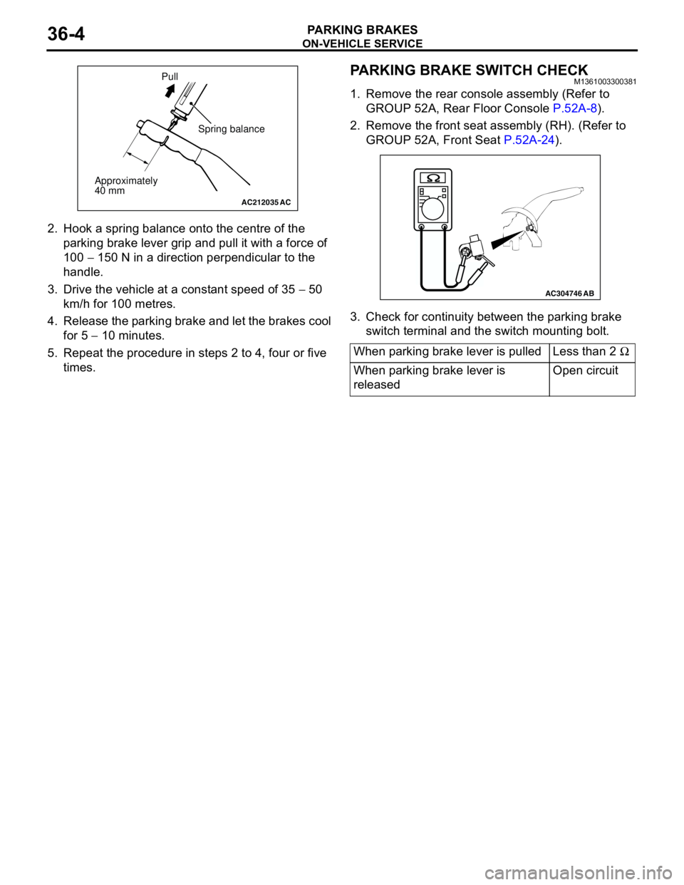
2. Hook a spring balance onto the centre of the
parking brake lever grip and pull it with a force of
100 − 150 N in a direction perpendicular to the
handle.
3. Drive the vehicle at a constant speed of 35 − 50
km/h for 100 metres.
4. Release the parking brake and let the brakes cool
for 5 − 10 minutes.
5. Repeat the procedure in steps 2 to 4, four or five
times.
PARKING BRAKE SWITCH CHECKM1361003300381
1. Remove the rear console assembly (Refer to
GROUP 52A, Rear Floor Console P.52A-8).
2. Remove the front seat assembly (RH). (Refer to
GROUP 52A, Front Seat P.52A-24).
3. Check for continuity between the parking brake
switch terminal and the switch mounting bolt.
AC212035AC
Spring balance
Approximately
40 mmPull
When parking brake lever is pulled Less than 2 Ω
When parking brake lever is
releasedOpen circuit
AC304746AB
Page 229 of 788
PARKING BRAKE LEVER
PARKING BRAKES36-5
PARKING BRAKE LEVER
REMOVAL AND INSTALLATIONM1361001300330
Pre-removal Operation
Rear Console Assembly and Rear Console Bracket Removal
(Refer to GROUP 52A, Rear Floor Console P.52A-8.)Post-installation Operation
•Parking Brake Lever Stroke Adjustment (Refer to P.36-3.)
•Rear Console Bracket and Rear Console Assembly
Installation (Refer to GROUP 52A, Rear Floor Console
P.52A-8.)
AC006199AB
4
5
21
3
A
AB
B
Ratchet pawlSection A - A
Section B - B
Ratchet pawl
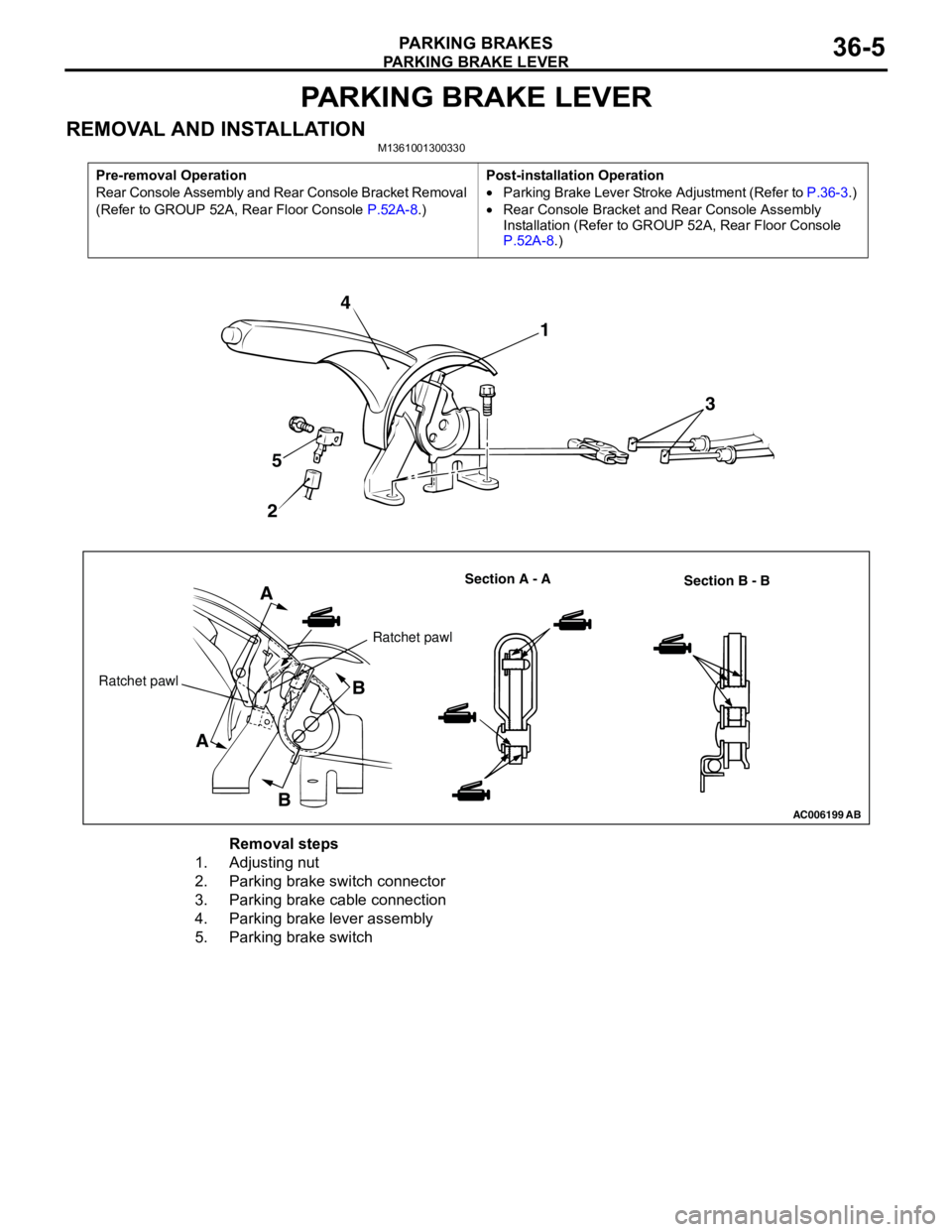
Removal steps
1. Adjusting nut
2. Parking brake switch connector
3. Parking brake cable connection
4. Parking brake lever assembly
5. Parking brake switch
Page 230 of 788
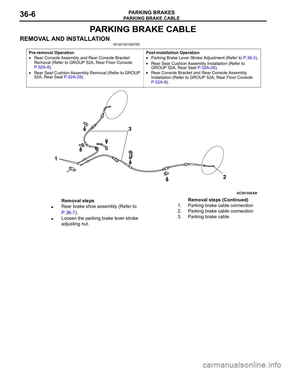
PARKING BRAKE CABLE
PARKING BRAKES36-6
PARKING BRAKE CABLE
REMOVAL AND INSTALLATIONM1361001900785
Pre-removal Operation
•Rear Console Assembly and Rear Console Bracket
Removal (Refer to GROUP 52A, Rear Floor Console
P.52A-8).
•Rear Seat Cushion Assembly Removal (Refer to GROUP
52A, Rear Seat P.52A-28).Post-installation Operation
•Parking Brake Lever Stroke Adjustment (Refer to P.36-3).
•Rear Seat Cushion Assembly Installation (Refer to
GROUP 52A, Rear Seat P.52A-28).
•Rear Console Bracket and Rear Console Assembly
Installation (Refer to GROUP 52A, Rear Floor Console
P.52A-8).
AC301226
1
AB
2
3
Removal steps
•Rear brake shoe assembly (Refer to
P.36-7).
•Loosen the parking brake lever stroke
adjusting nut.1. Parking brake cable connection
2. Parking brake cable connection
3. Parking brake cableRemoval steps (Continued)
Page 231 of 788
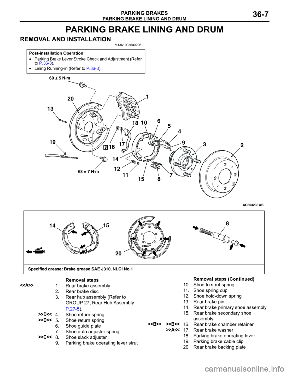
PARKING BRAKE LINING AND DRUM
PARKING BRAKES36-7
PARKING BRAKE LINING AND DRUM
REMOVAL AND INSTALLATIONM1361002500296
Post-installation Operation
•Parking Brake Lever Stroke Check and Adjustment (Refer
to P.36-3).
•Lining Running-in (Refer to P.36-3).
AC304238
19
60 ± 5 N·m
63 ± 7 N·m
AB
13
4
155
3
89
72 1
6
10
11 121718
14 16 20
N
15
14
208
Specified grease: Brake grease SAE J310, NLGI No.1
Removal steps
<>
1. Rear brake assembly
2. Rear brake disc
3. Rear hub assembly (Refer to
GROUP 27, Rear Hub Assembly
P.27-5).
>>D<<4. Shoe return spring
>>D<<5. Shoe return spring
6. Shoe guide plate
7. Shoe auto adjuster spring
>>C<<8. Shoe slack adjuster
9. Parking brake operating lever strut
10. Shoe to strut spring
11. Shoe spring cup
12. Shoe hold-down spring
13. Rear brake pin
14. Rear brake primary shoe assembly
15. Rear brake secondary shoe
assembly
<> >>B<<16. Rear brake chamber retainer
>>A<<17. Rear brake washer
18. Parking brake operating lever
19. Parking brake cable clip
20. Rear brake backing plate
Removal steps (Continued)
Page 232 of 788
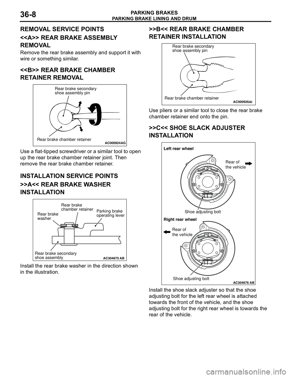
Page 233 of 788
PARKING BRAKE LINING AND DRUM
PARKING BRAKES36-9
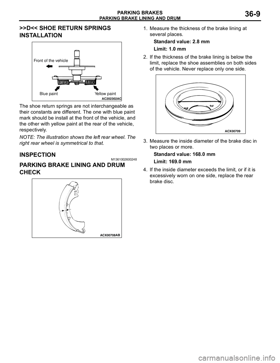
>>D<< SHOE RETURN SPRINGS
INSTALLATION
The shoe return springs are not interchangeable as
their constants are different. The one with blue paint
mark should be install at the front of the vehicle, and
the other with yellow paint at the rear of the vehicle,
respectively.
NOTE: The illustration shows the left rear wheel. The
right rear wheel is symmetrical to that.
INSPECTIONM1361002600248
PARKING BRAKE LINING AND DRUM
CHECK
1. Measure the thickness of the brake lining at
several places.
Standard value: 2.8 mm
Limit: 1.0 mm
2. If the thickness of the brake lining is below the
limit, replace the shoe assemblies on both sides
of the vehicle. Never replace only one side.
3. Measure the inside diameter of the brake disc in
two places or more.
Standard value: 168.0 mm
Limit: 169.0 mm
4. If the inside diameter exceeds the limit, or if it is
excessively worn on one side, replace the rear
brake disc.
AC202302AC
Front of the vehicle
Blue paint Yellow paint
ACX00708AB
ACX00709
Page 245 of 788
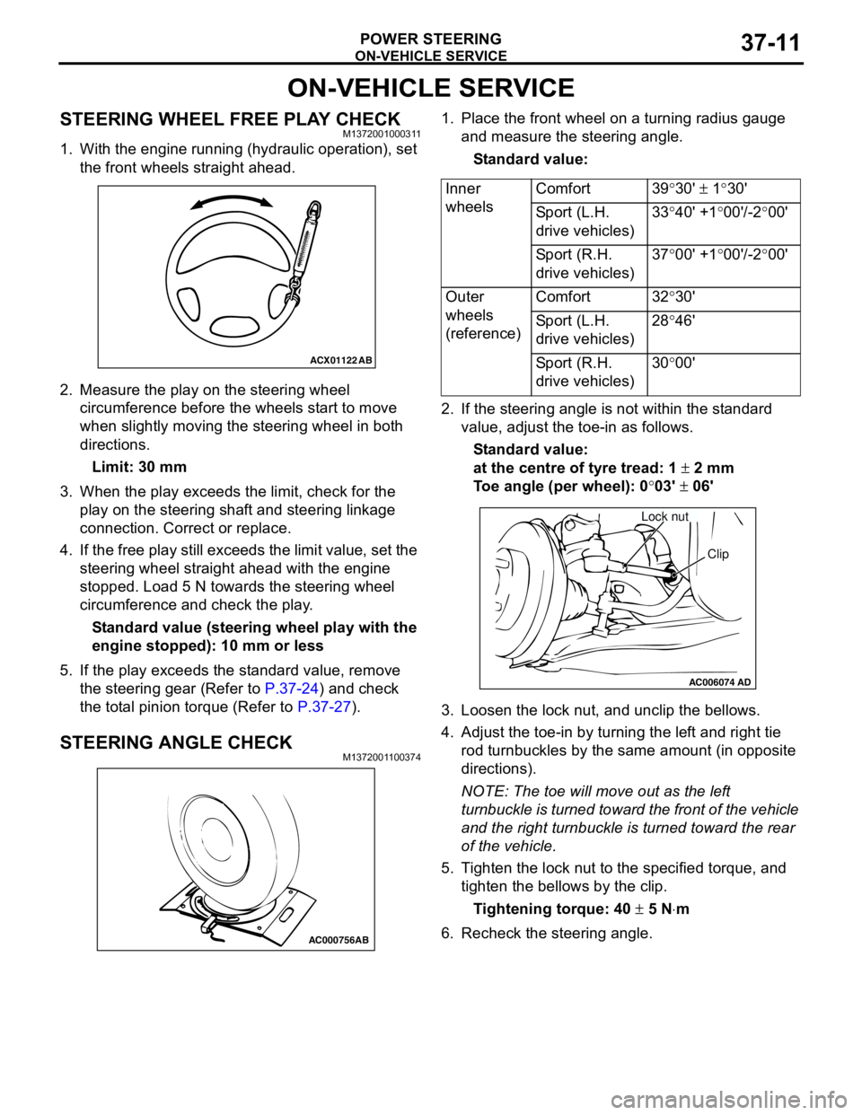
ON-VEHICLE SERVICE
POWER STEERING37-11
ON-VEHICLE SERVICE
STEERING WHEEL FREE PLAY CHECKM1372001000311
1. With the engine running (hydraulic operation), set
the front wheels straight ahead.
2. Measure the play on the steering wheel
circumference before the wheels start to move
when slightly moving the steering wheel in both
directions.
Limit: 30 mm
3. When the play exceeds the limit, check for the
play on the steering shaft and steering linkage
connection. Correct or replace.
4. If the free play still exceeds the limit value, set the
steering wheel straight ahead with the engine
stopped. Load 5 N towards the steering wheel
circumference and check the play.
Standard value (steering wheel play with the
engine stopped): 10 mm or less
5. If the play exceeds the standard value, remove
the steering gear (Refer to P.37-24) and check
the total pinion torque (Refer to P.37-27).
STEERING ANGLE CHECKM1372001100374
1. Place the front wheel on a turning radius gauge
and measure the steering angle.
Standard value:
2. If the steering angle is not within the standard
value, adjust the toe-in as follows.
Standard value:
at the centre of tyre tread: 1 ± 2 mm
Toe angle (per wheel): 0°03' ± 06'
3. Loosen the lock nut, and unclip the bellows.
4. Adjust the toe-in by turning the left and right tie
rod turnbuckles by the same amount (in opposite
directions).
NOTE: The toe will move out as the left
turnbuckle is turned toward the front of the vehicle
and the right turnbuckle is turned toward the rear
of the vehicle.
5. Tighten the lock nut to the specified torque, and
tighten the bellows by the clip.
Tightening torque: 40 ± 5 N⋅m
6. Recheck the steering angle.
ACX01122
AB
AC000756AB
Inner
wheelsComfort 39°30' ± 1°30'
Sport (L.H.
drive vehicles)33°40' +1°00'/-2°00'
Sport (R.H.
drive vehicles)37°00' +1°00'/-2°00'
Outer
wheels
(reference)Comfort 32°30'
Sport (L.H.
drive vehicles)28°46'
Sport (R.H.
drive vehicles)30°00'
AC006074AD
Lock nut
Clip
Page 258 of 788
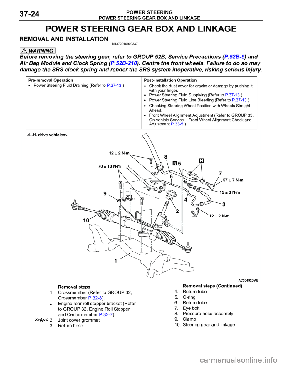
POWER STEERING GEAR BOX AND LINKAGE
POWER STEERING37-24
POWER STEERING GEAR BOX AND LINKAGE
REMOVAL AND INSTALLATIONM1372010900237
WARNING
Before removing the steering gear, refer to GROUP 52B, Service Precautions (P.52B-5) and
Air Bag Module and Clock Spring (P.52B-210). Centre the front wheels. Failure to do so may
damage the SRS clock spring and render the SRS system inoperative, risking serious injury.
Pre-removal Operation
•Power Steering Fluid Draining (Refer to P.37-13.)Post-installation Operation
•Check the dust cover for cracks or damage by pushing it
with your finger.
•Power Steering Fluid Supplying (Refer to P.37-13.)
•Power Steering Fluid Line Bleeding (Refer to P.37-13.)
•Checking Steering Wheel Position with Wheels Straight
Ahead.
•Front Wheel Alignment Adjustment (Refer to GROUP 33,
On-vehicle Service − Front Wheel Alignment Check and
Adjustment P.33-5.)
AC304920
AB
57 ± 7 N·m
15 ± 3 N·m 70 ± 10 N·m
7
3 8
5
6
9
1024
1
12 ± 2 N·m
12 ± 2 N·m
Removal steps
1. Crossmember (Refer to GROUP 32,
Crossmember P.32-8).
•Engine rear roll stopper bracket (Refer
to GROUP 32, Engine Roll Stopper
and Centermember P.32-7).
>>A<<2. Joint cover grommet
3. Return hose4. Return tube
5. O-ring
6. Return tube
7. Eye bolt
8. Pressure hose assembly
9. Clamp
10. Steering gear and linkageRemoval steps (Continued)