battery MITSUBISHI LANCER 2005 Repair Manual
[x] Cancel search | Manufacturer: MITSUBISHI, Model Year: 2005, Model line: LANCER, Model: MITSUBISHI LANCER 2005Pages: 788, PDF Size: 45.98 MB
Page 553 of 788
ON-VEHICLE SERVICE
HEATER, AIR CONDITIONER AND VENTILATION55-69
ON-VEHICLE SERVICE
SIGHT GLASS REFRIGERANT LEVEL
TEST
M1552008400378
1. Start the engine.
2. Operate the air-conditioner, and then set the
temperature to maximum cooling.
3. Hold the engine speed at 1500 r/min.
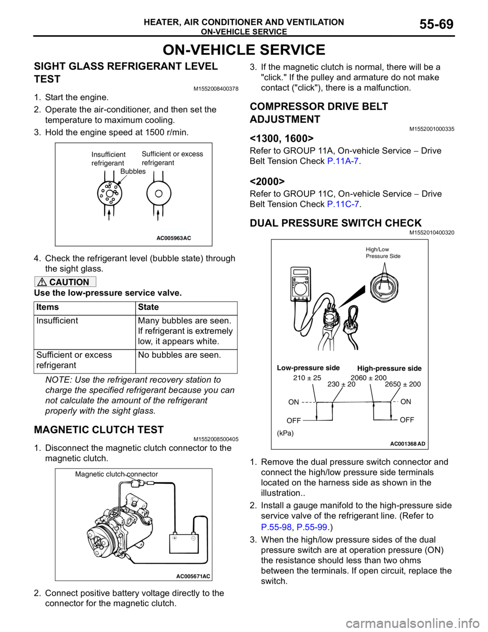
4. Check the refrigerant level (bubble state) through
the sight glass.
CAUTION
Use the low-pressure service valve.
NOTE: Use the refrigerant recovery station to
charge the specified refrigerant because you can
not calculate the amount of the refrigerant
properly with the sight glass.
MAGNETIC CLUTCH TESTM1552008500405
1. Disconnect the magnetic clutch connector to the
magnetic clutch.
2. Connect positive battery voltage directly to the
connector for the magnetic clutch.3. If the magnetic clutch is normal, there will be a
"click." If the pulley and armature do not make
contact ("click"), there is a malfunction.
COMPRESSOR DRIVE BELT
ADJUSTMENT
M1552001000335
<1300, 1600>
Refer to GROUP 11A, On-vehicle Service − Drive
Belt Tension Check P.11A-7.
<2000>
Refer to GROUP 11C, On-vehicle Service − Drive
Belt Tension Check P.11C-7.
DUAL PRESSURE SWITCH CHECKM1552010400320
1. Remove the dual pressure switch connector and
connect the high/low pressure side terminals
located on the harness side as shown in the
illustration..
2. Install a gauge manifold to the high-pressure side
service valve of the refrigerant line. (Refer to
P.55-98, P.55-99.)
3. When the high/low pressure sides of the dual
pressure switch are at operation pressure (ON)
the resistance should less than two ohms
between the terminals. If open circuit, replace the
switch. Items State
Insufficient Many bubbles are seen.
If refrigerant is extremely
low, it appears white.
Sufficient or excess
refrigerantNo bubbles are seen.
AC005963
Bubbles Insufficient
refrigerantSufficient or excess
refrigerant
AC
AC005671
Magnetic clutch connector
AC
AC001368AD High/Low
Pressure Side
Low-pressure side
High-pressure side
ON
OFFON
OFF
2650 ± 200 2060 ± 200230 ± 20 210 ± 25
(kPa)
Page 559 of 788
ON-VEHICLE SERVICE
HEATER, AIR CONDITIONER AND VENTILATION55-75
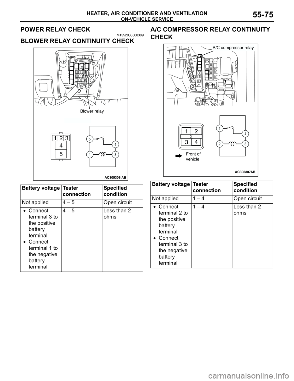
POWER RELAY CHECKM1552008800309
BLOWER RELAY CONTINUITY CHECKA/C COMPRESSOR RELAY CONTINUITY
CHECK
Battery voltage Tester
connectionSpecified
condition
Not applied 4 − 5 Open circuit
•Connect
terminal 3 to
the positive
battery
terminal
•Connect
terminal 1 to
the negative
battery
terminal4 − 5 Less than 2
ohms
AC305308
4
5 1
235
14
3
Blower relay
AB
Battery voltage Tester
connectionSpecified
condition
Not applied 1 − 4 Open circuit
•Connect
terminal 2 to
the positive
battery
terminal
•Connect
terminal 3 to
the negative
battery
terminal1 − 4 Less than 2
ohms
AC305307
A/C compressor relay
AB
21
34
1
24
3
Front of
vehicle
Page 560 of 788
ON-VEHICLE SERVICE
HEATER, AIR CONDITIONER AND VENTILATION55-76
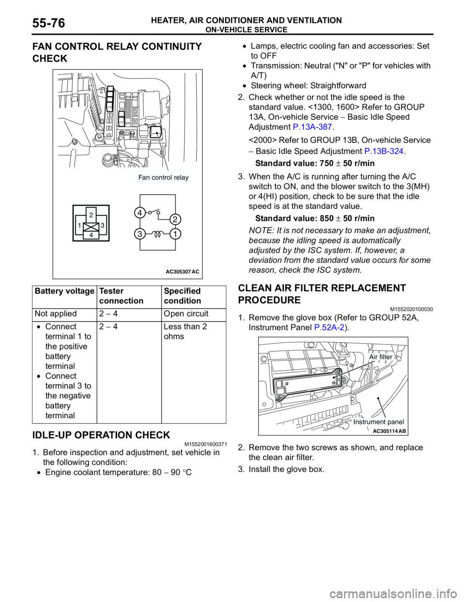
FAN CONTROL RELAY CONTINUITY
CHECK
IDLE-UP OPERATION CHECK
M1552001600371
1. Before inspection and adjustment, set vehicle in
the following condition:
•Engine coolant temperature: 80 − 90 °C•Lamps, electric cooling fan and accessories: Set
to OFF
•Transmission: Neutral ("N" or "P" for vehicles with
A/T)
•Steering wheel: Straightforward
2. Check whether or not the idle speed is the
standard value. <1300, 1600> Refer to GROUP
13A, On-vehicle Service − Basic Idle Speed
Adjustment P.13A-387.
<2000> Refer to GROUP 13B, On-vehicle Service
− Basic Idle Speed Adjustment P.13B-324.
Standard value: 750 ± 50 r/min
3. When the A/C is running after turning the A/C
switch to ON, and the blower switch to the 3(MH)
or 4(HI) position, check to be sure that the idle
speed is at the standard value.
Standard value: 850 ± 50 r/min
NOTE: It is not necessary to make an adjustment,
because the idling speed is automatically
adjusted by the ISC system. If, however, a
deviation from the standard value occurs for some
reason, check the ISC system.
CLEAN AIR FILTER REPLACEMENT
PROCEDURE
M1552020100030
1. Remove the glove box (Refer to GROUP 52A,
Instrument Panel P.52A-2).
2. Remove the two screws as shown, and replace
the clean air filter.
3. Install the glove box. Battery voltage Tester
connectionSpecified
condition
Not applied 2 − 4 Open circuit
•Connect
terminal 1 to
the positive
battery
terminal
•Connect
terminal 3 to
the negative
battery
terminal2 − 4 Less than 2
ohms
AC305307
Fan control relay
13
4 2
3 4
1 2
AC
AC305114AB
Air filter
Instrument panel
Page 570 of 788
BLOWERMOTOR, RESISTOR AND OUTSIDE/ INSIDE AIR SELECTION DAMPER CONTROL MOTOR
HEATER, AIR CONDITIONER AND VENTILATION55-86
REMOVAL SERVICE POINT
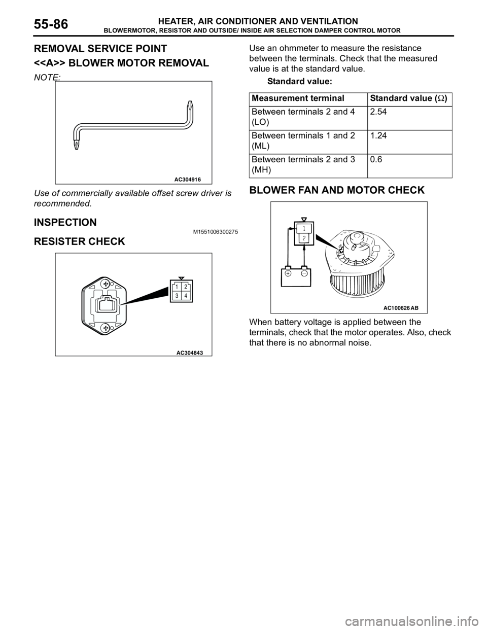
<> BLOWER MOTOR REMOVAL
NOTE:
Use of commercially available offset screw driver is
recommended.
INSPECTIONM1551006300275
RESISTER CHECK
Use an ohmmeter to measure the resistance
between the terminals. Check that the measured
value is at the standard value.
Standard value:
BLOWER FAN AND MOTOR CHECK
When battery voltage is applied between the
terminals, check that the motor operates. Also, check
that there is no abnormal noise.
AC304916
12
34
AC304843
Measurement terminal Standard value (Ω)
Between terminals 2 and 4
(LO)2.54
Between terminals 1 and 2
(ML)1.24
Between terminals 2 and 3
(MH)0.6
AC100626AB
Page 571 of 788
BLOWERMOTOR, RESISTOR AND OUTSIDE/ INSIDE AIR SELECTION DAMPER CONTROL MOTOR
HEATER, AIR CONDITIONER AND VENTILATION55-87
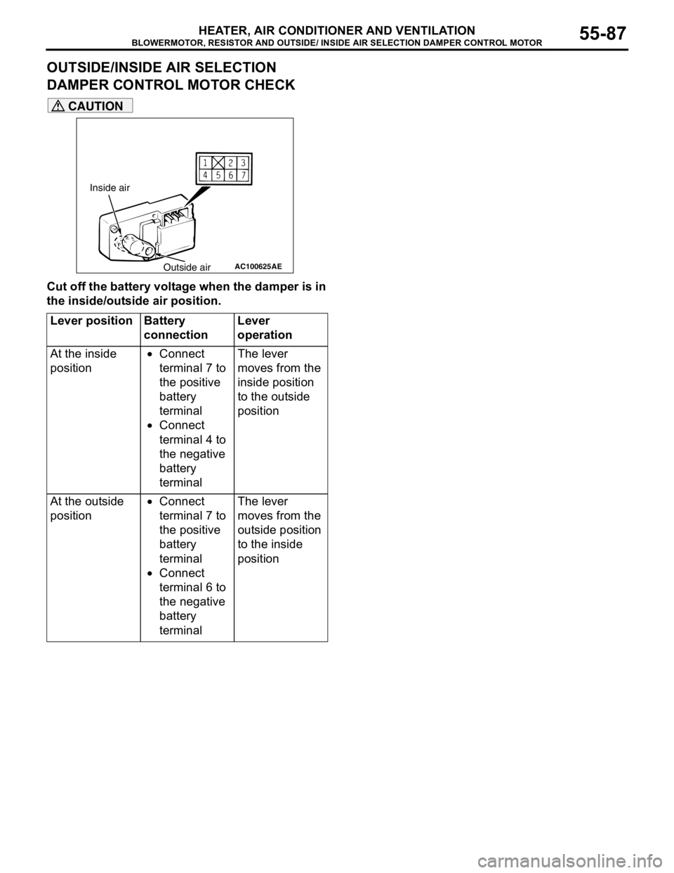
OUTSIDE/INSIDE AIR SELECTION
DAMPER CONTROL MOTOR CHECK
CAUTION
Cut off the battery voltage when the damper is in
the inside/outside air position.
Lever position Battery
connectionLever
operation
At the inside
position•Connect
terminal 7 to
the positive
battery
terminal
•Connect
terminal 4 to
the negative
battery
terminalThe lever
moves from the
inside position
to the outside
position
At the outside
position•Connect
terminal 7 to
the positive
battery
terminal
•Connect
terminal 6 to
the negative
battery
terminalThe lever
moves from the
outside position
to the inside
position
AC100625
Inside air
Outside air
AE
Page 577 of 788

COMPRESSOR ASSEMBLY AND TENSION PULLEY
HEATER, AIR CONDITIONER AND VENTILATION55-93
INSTALLATION SERVICE POINT
>>A<< A/C COMPRESSOR
INSTALLATION
If a new compressor is installed, first adjust the
amount of oil according to the procedures described
below, and then install the compressor.
1. Measure the amount (X mL) of oil within the
removed compressor.
2. Drain (from the new compressor) the amount of
oil calculated according to the following formula,
and then install the new compressor.
New compressor oil amount = 140mL <1300,
1600>, 120 mL <2000>
140 mL−X mL = Y mL <1300, 1600>
120 mL−X mL = Y mL <2000>
NOTE: Y mL indicates the amount of oil in the
refrigerant line, the condenser, the evaporator, etc.
NOTE: When replacing the following parts at the
same times as the compressor, subtract the rated oil
amount of the each part from Y mL and discharge
from the new compressor.
Quantity:
•Evaporator: 60 mL
•Condenser: 15 mL
•Suction hose: 10 mL
•Receiver: 10 mL
INSPECTIONM1552014300949
COMPRESSOR MAGNETIC CLUTCH
OPERATION CHECK
Connect the compressor connector terminal to the
battery positive (+) terminal and earth the battery’s
negative (−) terminal to the compressor unit. At that
time, the magnetic clutch should make a definite
operating sound.
AC005671
Magnetic clutch connector
AC
Page 581 of 788
CONDENSER AND CONDENSER FAN MOTOR
HEATER, AIR CONDITIONER AND VENTILATION55-97
REMOVAL SERVICE POINT
<> FLEXIBLE SUCTION HOSE AND
LIQUID PIPE A DISCONNECTION
CAUTION
As the compressor oil and receiver are highly
moisture absorbent, use a non-porous material
to plug the hose and nipples.
To prevent the entry of dust or other foreign bodies,
plug the dismantled hose and condenser assembly
nipples.
INSTALLATION SERVICE POINT
>>A<< CONDENSER INSTALLATION
When replacing the condenser, refill it with a
specified amount of compressor oil and install it. (to
the vehicle).
Compressor oil: SUN PAG 56
Quantity: 15 mL
INSPECTIONM1552014300961
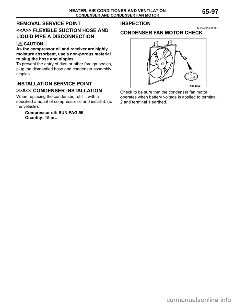
CONDENSER FAN MOTOR CHECK
Check to be sure that the condenser fan motor
operates when battery voltage is applied to terminal
2 and terminal 1 earthed.
A304852
12
Page 589 of 788
ECU
COMPONENT LOCATIONS70-3
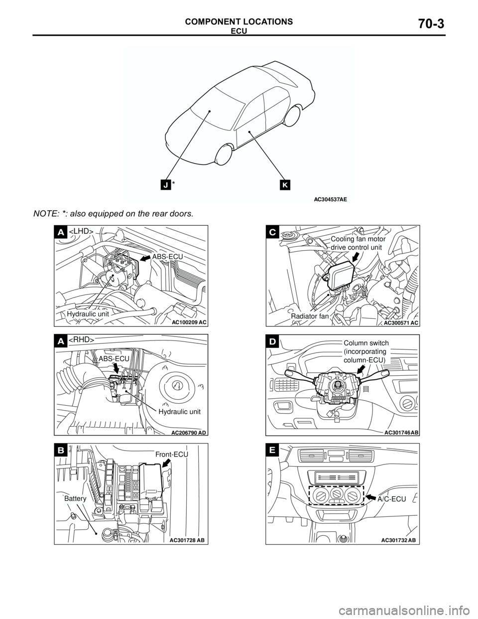
NOTE: *: also equipped on the rear doors.
AC304537
JK*
AE
AC100209AC
A
ABS-ECU
Hydraulic unit
AC206790
A
AD
ABS-ECU
Hydraulic unit
AC301728AB
BFront-ECU
Battery
AC300571
C
ACRadiator fan
Cooling fan motor
drive control unit
AC301746
DColumn switch
(incorporating
column-ECU)
AB
AC301732AB
E
A/C-ECU
Page 596 of 788
FUSIBLE LINK AND FUSE
COMPONENT LOCATIONS70-10
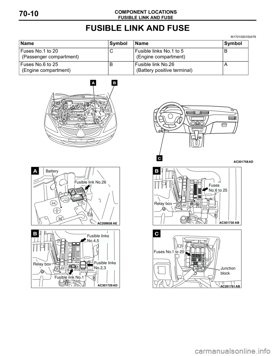
FUSIBLE LINK AND FUSE
M1701000100476
Name Symbol Name Symbol
Fuses No.1 to 20
(Passenger compartment)C Fusible links No.1 to 5
(Engine compartment)B
Fuses No.6 to 25
(Engine compartment)B Fusible link No.26
(Battery positive terminal)A
AC301758AD
AB
C
AC208658AE
A
Fusible link No.26
Battery
AC301729AD
B
Fusible link No.1
Relay box
Fusible links
No.4,5
Fusible links
No.2,3
AC301730
B
AB
Fuses
No.6 to 25
Relay box
AC301761
C
AB
Fuses No.1 to 20
Junction
block
Page 608 of 788

OVERALL CONFIGURATION DIAGRAM
CONFIGURATION DIAGRAMS80-2
OVERALL CONFIGURATION DIAGRAM
OVERALL WIRING DIAGRAM
NOTE: .
1. This illustration shows only major wiring harnesses.
2. *: also equipped at the right side.
AC301175
AB
Front wiring
harness (RH)Control wiring
harnessInstrument panel
wiring harnessRoof wiring
harnessFloor wiring
harness (RH)
Battery wiring
harnessFront wiring
harness (LH)Front door
wiring harness Floor wiring
harness (LH)Fuel wiring
harnessRear door
wiring harness
Front bumper
wiring harness
Rear bumper
wiring harness
**