23a MITSUBISHI LANCER 2005 Workshop Manual
[x] Cancel search | Manufacturer: MITSUBISHI, Model Year: 2005, Model line: LANCER, Model: MITSUBISHI LANCER 2005Pages: 788, PDF Size: 45.98 MB
Page 1 of 788
GROUP INDEX
00General . . . . . . . . . . . . . . . . . . . . . . . .
11Engine. . . . . . . . . . . . . . . . . . . . . . . . .
12Engine Lubrication . . . . . . . . . . . . . .
13Fuel . . . . . . . . . . . . . . . . . . . . . . . . . . .
14Engine Cooling . . . . . . . . . . . . . . . . .
15Intake and Exhaust . . . . . . . . . . . . . .
16Engine Electrical . . . . . . . . . . . . . . . .
17Engine and Emission Control . . . . .
21Clutch . . . . . . . . . . . . . . . . . . . . . . . . .
22Manual Transmission . . . . . . . . . . . .
23Automatic Transmission. . . . . . . . . .
26Front Axle . . . . . . . . . . . . . . . . . . . . . .
27Rear Axle . . . . . . . . . . . . . . . . . . . . . .
31Wheel and Tyre . . . . . . . . . . . . . . . . .
32Power Plant Mount . . . . . . . . . . . . . .
33Front Suspension . . . . . . . . . . . . . . .
34Rear Suspension . . . . . . . . . . . . . . . .
35Service Brakes . . . . . . . . . . . . . . . . . .
36Parking Brakes . . . . . . . . . . . . . . . . .
37Power Steering . . . . . . . . . . . . . . . . .
42Body . . . . . . . . . . . . . . . . . . . . . . . . . .
51Exterior . . . . . . . . . . . . . . . . . . . . . . . .
52 . . . . . . . . . .
54Chassis Electrical . . . . . . . . . . . . . . .
55 . . . . . . .
70Component Locations. . . . . . . . . . . .
80Configration Diagrams . . . . . . . . . . .
90Circuit Diagrams . . . . . . . . . . . . . . . .
LANCER /
LANCER WAGON
WORKSHOP MANUAL
FOREWORD
This Workshop manual contains procedures for
service mechanics, including removal, disassembly,
inspection, adjustment, reassembly and installation.
Use the following manuals in combination with this
manual as required.
TECHNICAL INFORMATION MANUAL
PYME0302
PYME0302-A
WORKSHOP MANUAL
CHASSIS GROUP PWME0302
BODY REPAIR MANUAL
PBME0302
PBME0302-A
PARTS CATALOGUE
B606K005A_
All information, illustrations and product descriptions
contained in this manual are current as at the time of
publication. We, however, reserve the right to make
changes at any time without prior notice or obligation.
Mitsubishi Motors Corporation May 2004
Heater, Air Conditioner and
Ventilation Interior and Supplemental
Restraint System (SRS)
Page 131 of 788

23-1
GROUP 23
AUTOMATIC
TRANSMISSION
CONTENTS
AUTOMATIC TRANSMISSION (FF) . . . . . . . . . . . . . . . . . . . . . .23A
AUTOMATIC TRANSMISSION OVERHAUL . . . . . . . . . . . . . . .23B
Page 165 of 788
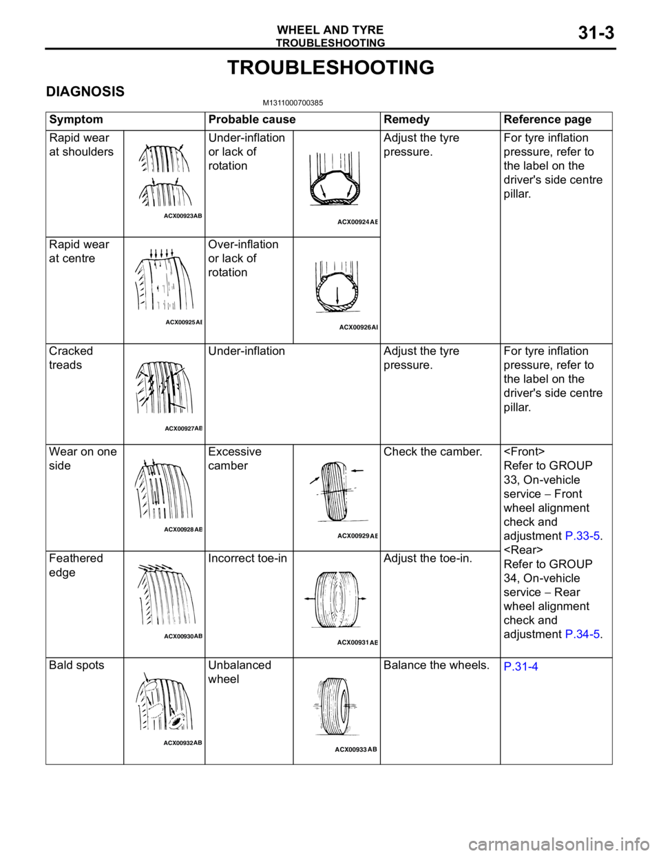
TROUBLESHOOTING
WHEEL AND TYRE31-3
TROUBLESHOOTING
DIAGNOSISM1311000700385
Symptom Probable cause Remedy Reference page
Rapid wear
at shouldersUnder-inflation
or lack of
rotationAdjust the tyre
pressure.For tyre inflation
pressure, refer to
the label on the
driver's side centre
pillar.
Rapid wear
at centreOver-inflation
or lack of
rotation
Cracked
treadsUnder-inflation Adjust the tyre
pressure.For tyre inflation
pressure, refer to
the label on the
driver's side centre
pillar.
Wear on one
sideExcessive
camberCheck the camber.
Refer to GROUP
33, On-vehicle
service − Front
wheel alignment
check and
adjustment P.33-5.
Refer to GROUP
34, On-vehicle
service − Rear
wheel alignment
check and
adjustment P.34-5. Feathered
edgeIncorrect toe-in Adjust the toe-in.
Bald spots Unbalanced
wheelBalance the wheels.
P.31-4
ACX00923ABACX00924
AB
ACX00925ABACX00926AB
ACX00927AB
ACX00928
ABACX00929
AB
ACX00930ABACX00931
AB
ACX00932ABACX00933AB
Page 250 of 788
ON-VEHICLE SERVICE
POWER STEERING37-16
WARNING
•If the vehicle continues to be driven after
the collision absorbing mechanism has
operated, the steering column shaft may
be damaged while it is in use.
•If there is a slack in the one-way capsule,
do not attempt to repair it but replace the
steering column shaft assembly.
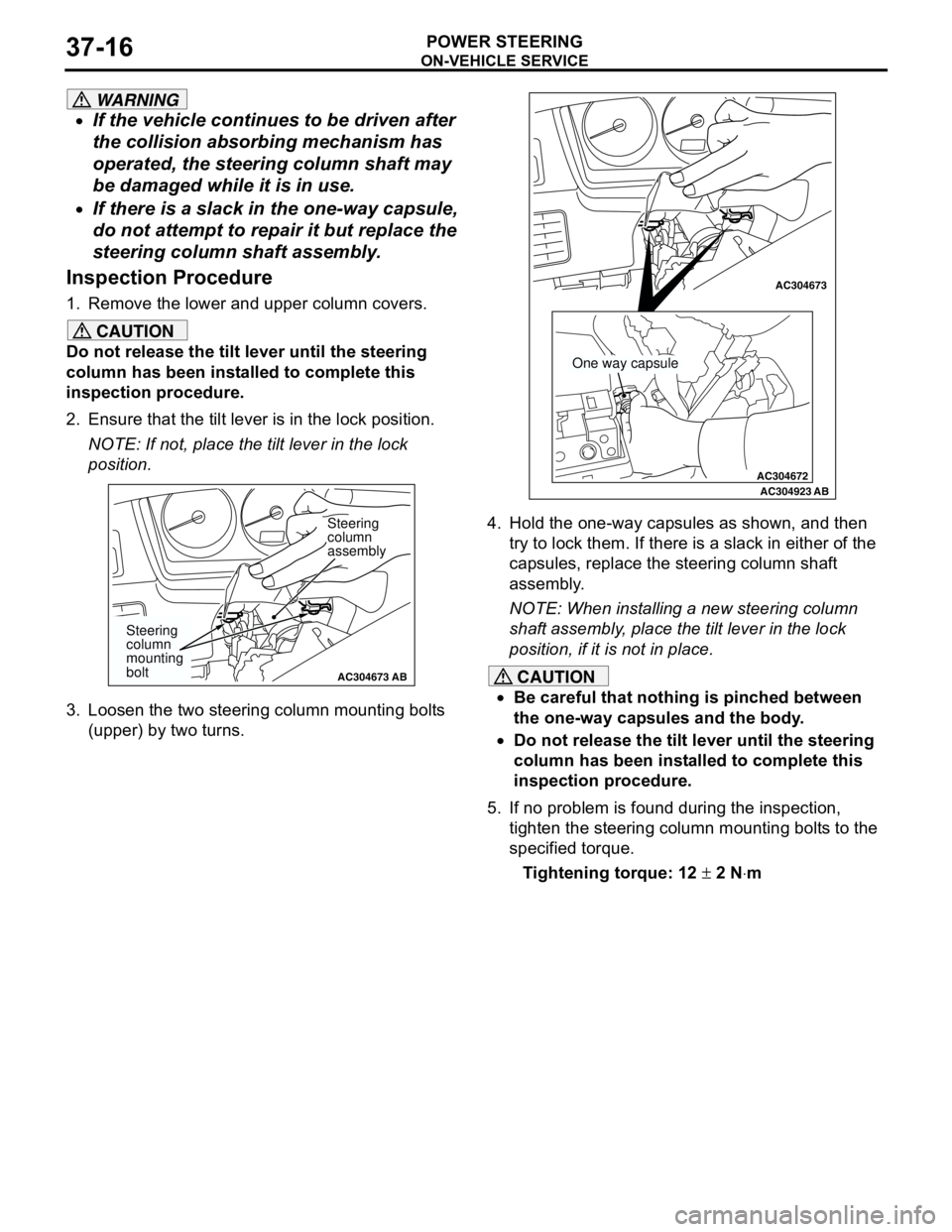
Inspection Procedure
1. Remove the lower and upper column covers.
CAUTION
Do not release the tilt lever until the steering
column has been installed to complete this
inspection procedure.
2. Ensure that the tilt lever is in the lock position.
NOTE: If not, place the tilt lever in the lock
position.
3. Loosen the two steering column mounting bolts
(upper) by two turns.4. Hold the one-way capsules as shown, and then
try to lock them. If there is a slack in either of the
capsules, replace the steering column shaft
assembly.
NOTE: When installing a new steering column
shaft assembly, place the tilt lever in the lock
position, if it is not in place.
CAUTION
•Be careful that nothing is pinched between
the one-way capsules and the body.
•Do not release the tilt lever until the steering
column has been installed to complete this
inspection procedure.
5. If no problem is found during the inspection,
tighten the steering column mounting bolts to the
specified torque.
Tightening torque: 12 ± 2 N⋅m
AC304673AC304673
Steering
column
assembly
AB
Steering
column
mounting
bolt
AC304672
AC304673AC304673
AC304923AB
One way capsule
Page 255 of 788
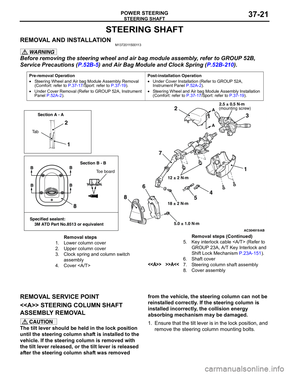
STEERING SHAFT
POWER STEERING37-21
STEERING SHAFT
REMOVAL AND INSTALLATIONM1372011500113
WARNING
Before removing the steering wheel and air bag module assembly, refer to GROUP 52B,
Service Precautions (P.52B-5) and Air Bag Module and Clock Spring (P.52B-210).
REMOVAL SERVICE POINT
<> STEERING COLUMN SHAFT
ASSEMBLY REMOVAL
CAUTION
The tilt lever should be held in the lock position
until the steering column shaft is installed to the
vehicle. If the steering column is removed with
the tilt lever released, or the tilt lever is released
after the steering column shaft was removed from the vehicle, the steering column can not be
reinstalled correctly. If the steering column is
installed incorrectly, the collision energy
absorbing mechanism may be damaged.
1. Ensure that the tilt lever is in the lock position, and
remove the steering column mounting bolts.
Pre-removal Operation
•Steering Wheel and Air bag Module Assembly Removal
(Comfort: refer to P.37-17/Sport: refer to P.37-19).
•Under Cover Removal (Refer to GROUP 52A, Instrument
Panel P.52A-2).Post-installation Operation
•Under Cover Installation (Refer to GROUP 52A,
Instrument Panel P.52A-2).
•Steering Wheel and Air bag Module Assembly Installation
(Comfort: refer to P.37-17/Sport: refer to P.37-19).
AC304919AB
12 ± 2 N·m
18 ± 2 N·m
5.0 ± 1.0 N·m
1 2
73 2
1
8
86
A
A
Ta bSection A - A
Section B - B
BB
Toe board
Specified sealant:
3M ATD Part No.8513 or equivalent
BB
4
5
(mounting screw)2.5 ± 0.5 N·m
Removal steps
1. Lower column cover
2. Upper column cover
3. Clock spring and column switch
assembly
4. Cover 5. Key interlock cable (Refer to
GROUP 23A, A/T Key Interlock and
Shift Lock Mechanism P.23A-151).
6. Shaft cover
<> >>A<<7. Steering column shaft assembly
8. Cover assemblyRemoval steps (Continued)
Page 348 of 788
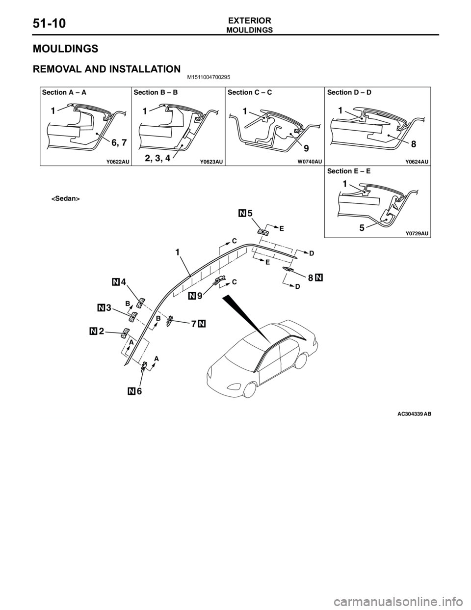
MOULDINGS
EXTERIOR51-10
MOULDINGS
REMOVAL AND INSTALLATIONM1511004700295
AC304339 Y0622AU
Y0624AUY0623AU
Y0729AU
W0740AU
Section A – A
Section E – E
AB
N
N
N
N
N
C
C
EE
DD
B
B
A
A
1
2
6
4
3
5
7
8
9
N
N
N
111
98
51
1
6, 7
2, 3, 4
Page 409 of 788
IGNITION SWITCH
CHASSIS ELECTRICAL54A-21
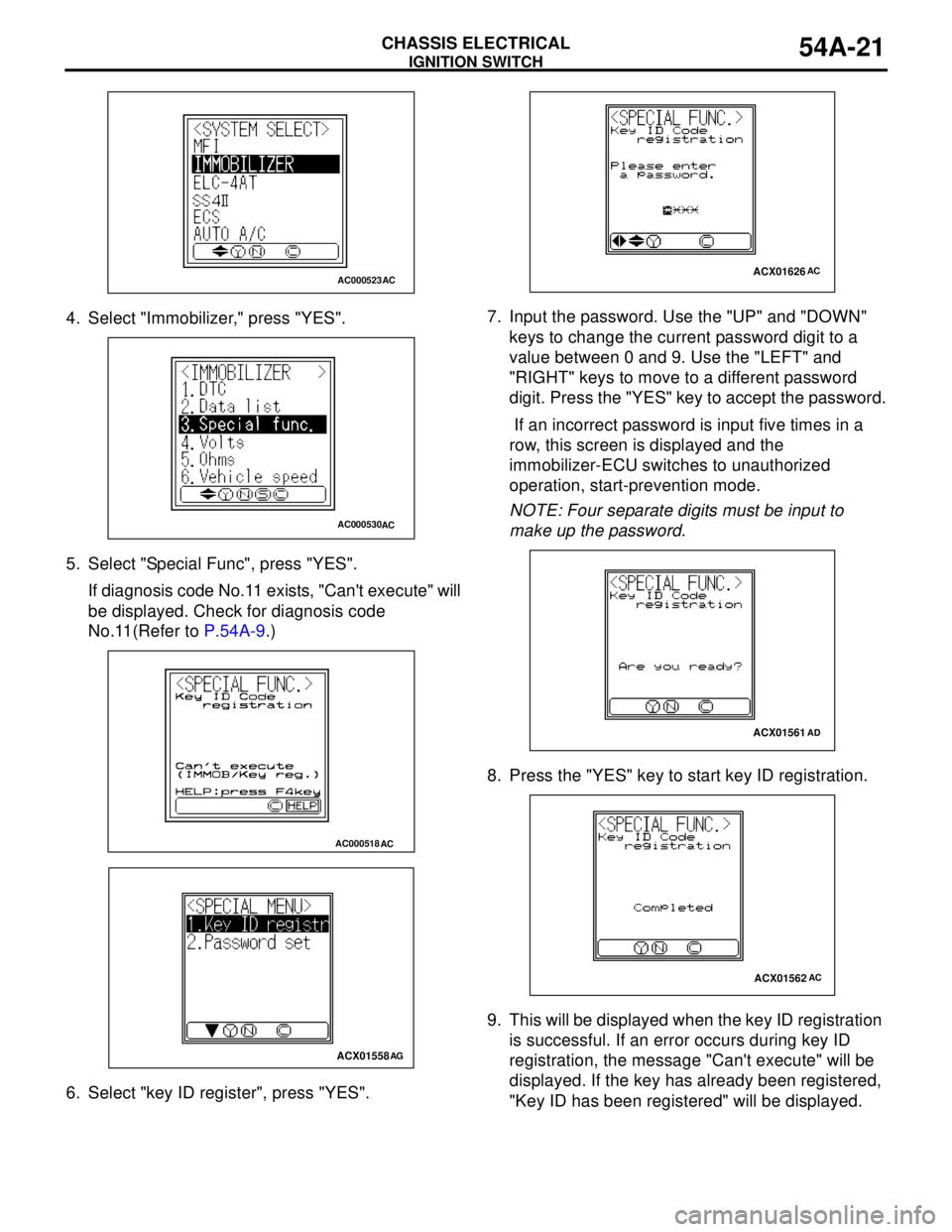
4. Select "Immobilizer," press "YES".
5. Select "Special Func", press "YES".
If diagnosis code No.11 exists, "Can't execute" will
be displayed. Check for diagnosis code
No.11(Refer to P.54A-9.)
6. Select "key ID register", press "YES".7. Input the password. Use the "UP" and "DOWN"
keys to change the current password digit to a
value between 0 and 9. Use the "LEFT" and
"RIGHT" keys to move to a different password
digit. Press the "YES" key to accept the password.
If an incorrect password is input five times in a
row, this screen is displayed and the
immobilizer-ECU switches to unauthorized
operation, start-prevention mode.
NOTE: Four separate digits must be input to
make up the password.
8. Press the "YES" key to start key ID registration.
9. This will be displayed when the key ID registration
is successful. If an error occurs during key ID
registration, the message "Can't execute" will be
displayed. If the key has already been registered,
"Key ID has been registered" will be displayed.
AC000523AC
AC000530AC
AC000518AC
ACX01558AG
ACX01626AC
ACX01561AD
ACX01562AC
Page 410 of 788
IGNITION SWITCH
CHASSIS ELECTRICAL54A-22
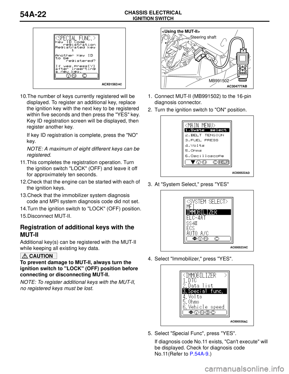
10.The number of keys currently registered will be
displayed. To register an additional key, replace
the ignition key with the next key to be registered
within five seconds and then press the "YES" key.
Key ID registration screen will be displayed, then
register another key.
If key ID registration is complete, press the "NO"
key.
NOTE: A maximum of eight different keys can be
registered.
11.This completes the registration operation. Turn
the ignition switch "LOCK" (OFF) and leave it off
for approximately ten seconds.
12.Check that the engine can be started with each of
the ignition keys.
13.Check that the immobilizer system diagnosis
code and MPI system diagnosis code did not set.
14.Turn the ignition switch to "LOCK" (OFF) position.
15.Disconnect MUT-II.
Registration of additional keys with the
MUT-II
Additional key(s) can be registered with the MUT-II
while keeping all existing key data.
CAUTION
To prevent damage to MUT-II, always turn the
ignition switch to "LOCK" (OFF) position before
connecting or disconnecting MUT-II.
NOTE: To register additional keys with the MUT-II,
no registered keys must be lost.1. Connect MUT-II (MB991502) to the 16-pin
diagnosis connector.
2. Turn the ignition switch to "ON" position.
3. At "System Select," press "YES"
4. Select "Immobilizer," press "YES".
5. Select "Special Func", press "YES".
If diagnosis code No.11 exists, "Can't execute" will
be displayed. Check for diagnosis code
No.11(Refer to P.54A-9.)
ACX01563ACAC304777
Steering shaft
AB
MB991502
AC000522AD
AC000523AC
AC000530AC
Page 426 of 788
COMBINATION METER ASSEMBLY
CHASSIS ELECTRICAL54A-38
TECHNICAL DESCRIPTION (COMMENT)
The engine-ECU and its associated components, the
combination meter assembly, the wiring harness, or
the connector(s) may be defective.
TROUBLESHOOTING HINTS
•Malfunction of the vehicle speed sensor
•Malfunction of the engine-ECU
•Malfunction of the combination meter assembly
•The wiring harness or connectors may have
loose, corroded, or damaged terminals, or
terminals pushed back in the connector.
DIAGNOSIS PROCEDURE
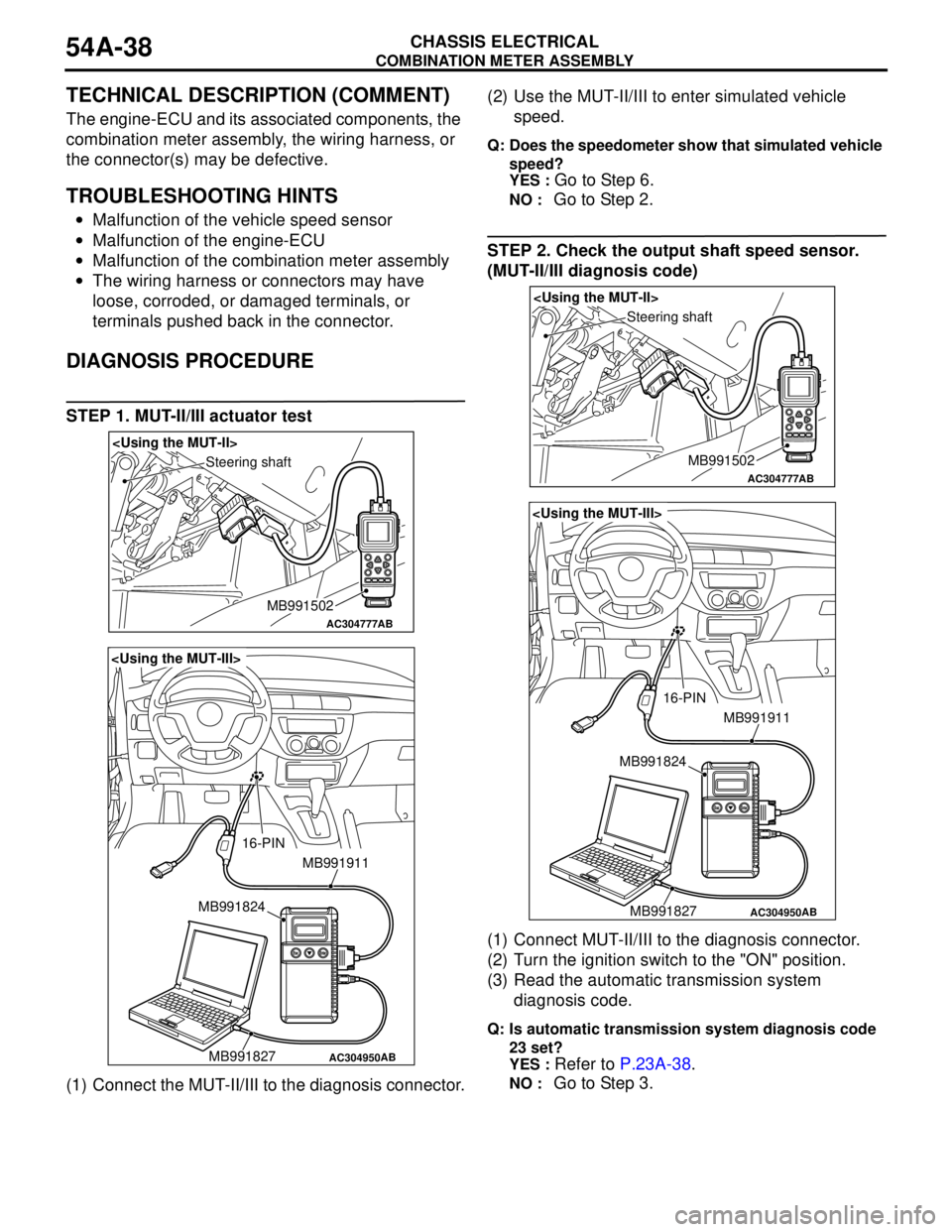
STEP 1. MUT-II/III actuator test
(1) Connect the MUT-II/III to the diagnosis connector.(2) Use the MUT-II/III to enter simulated vehicle
speed.
Q: Does the speedometer show that simulated vehicle
speed?
YES :
Go to Step 6.
NO : Go to Step 2.
STEP 2. Check the output shaft speed sensor.
(MUT-II/III diagnosis code)
(1) Connect MUT-II/III to the diagnosis connector.
(2) Turn the ignition switch to the "ON" position.
(3) Read the automatic transmission system
diagnosis code.
Q: Is automatic transmission system diagnosis code
23 set?
YES :
Refer to P.23A-38.
NO : Go to Step 3.
AC304777
Steering shaft
AB
MB991502
AC304950
MB991911
16-PIN
MB991827 MB991824
AB
AC304777
Steering shaft
AB
MB991502
AC304950
MB991911
16-PIN
MB991827 MB991824
AB
Page 452 of 788
COMBINATION METER ASSEMBLY
CHASSIS ELECTRICAL54A-64
INSPECTIONM1543019502407
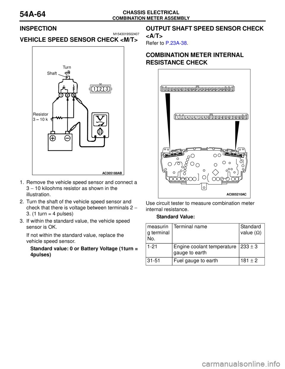
VEHICLE SPEED SENSOR CHECK
1. Remove the vehicle speed sensor and connect a
3 − 10 kiloohms resistor as shown in the
illustration.
2. Turn the shaft of the vehicle speed sensor and
check that there is voltage between terminals 2 −
3. (1 turn = 4 pulses)
3. If within the standard value, the vehicle speed
sensor is OK.
If not within the standard value, replace the
vehicle speed sensor.
Standard value: 0 or Battery Voltage (1turn =
4pulses)
OUTPUT SHAFT SPEED SENSOR CHECK
Refer to P.23A-38.
COMBINATION METER INTERNAL
RESISTANCE CHECK
Use circuit tester to measure combination meter
internal resistance.
Standard Value:
AC305188AB
Tu r n
Shaft
Resistor
3 – 10 k
measurin
g terminal
No.Terminal name Standard
value (Ω)
1-21 Engine coolant temperature
gauge to earth233 ± 3
31-51 Fuel gauge to earth 181 ± 2
AC005210AC