Head MITSUBISHI LANCER 2005 Workshop Manual
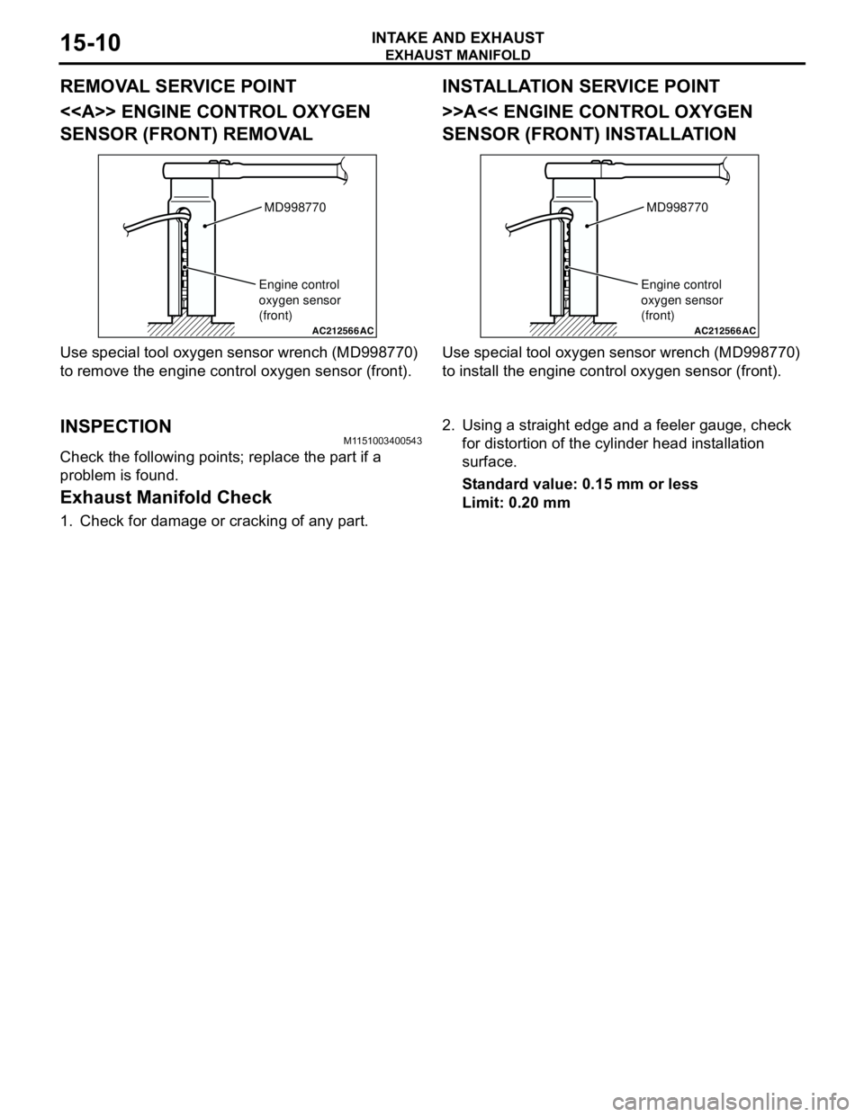
[x] Cancel search | Manufacturer: MITSUBISHI, Model Year: 2005, Model line: LANCER, Model: MITSUBISHI LANCER 2005Pages: 788, PDF Size: 45.98 MB
Page 59 of 788
EXHAUST MANIFOLD
INTAKE AND EXHAUST15-7
INSPECTIONM1151003100616
Check the following points; replace the part if a
problem is found.
Inlet Manifold Check
1. Check for damage or cracking of any part.2. Clogging of the negative pressure (vacuum) outlet
port, or clogging of the exhaust gas recirculation
passages.
3. Using a straight edge and feeler gauge, check for
distortion of the cylinder head installation surface.
Standard value: 0.15 mm or less
Limit: 0.20 mm
EXHAUST MANIFOLD
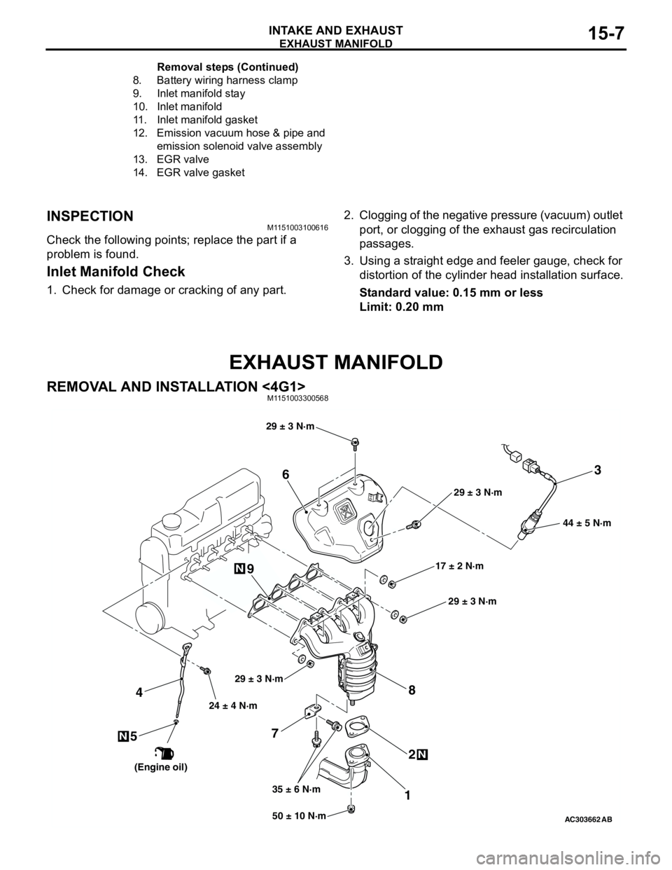
REMOVAL AND INSTALLATION <4G1>M1151003300568
8. Battery wiring harness clamp
9. Inlet manifold stay
10. Inlet manifold
11. Inlet manifold gasket
12. Emission vacuum hose & pipe and
emission solenoid valve assembly
13. EGR valve
14. EGR valve gasketRemoval steps (Continued)
AC30366250 ± 10 N·m 24 ± 4 N·m
35 ± 6 N·m17 ± 2 N·m 29 ± 3 N·m
N
3
7
12 4
N
6
8
44 ± 5 N·m
AB
9
5N
29 ± 3 N·m
29 ± 3 N·m
29 ± 3 N·m
(Engine oil)
Page 62 of 788
Page 68 of 788
CHARGING SYSTEM
ENGINE ELECTRICAL16-4
2. Turn the ignition switch to the "LOCK" (OFF)
position.
3. Disconnect the negative battery cable.
4. Connect a clamp-type DC test ammeter with a
range of 0 − 120 A to the alternator "B" terminal
output wire.
NOTE: The way of disconnecting the alternator
output wire and of connecting the ammeter is
possibly not found the problem that the output
current is dropping due to the insufficient
connection between terminal "B" and the output
wire.
5. Connect a digital-type voltmeter between the
alternator "B" terminal and the battery (+)
terminal. [Connect the (+) lead of the voltmeter to
the "B" terminal and the connect the (-) lead of the
voltmeter to the battery (+) cable].
6. Reconnect the negative battery cable.
7. Connect a tachometer or the MUT-II/III (Refer to
GROUP 11A − On-vehicle Service − Idle speed
check <4G1> P.11A-11 or GROUP 11C −
On-vehicle Service − Idle speed check <4G6>
P.11C-11).
8. Leave the hood open.
9. Start the engine.
10.With the engine running at 2,500 r/min, turn the
headlamps and other lamps on and off to adjust
the alternator load so that the value displayed on
the ammeter is slightly above 30 A.Adjust the engine speed by gradually decreasing
it until the value displayed on the ammeter is 30
A. Take a reading of the value displayed on the
voltmeter at this time.
Limit: maximum 0.3 V
NOTE: When the alternator output is high and the
value displayed on the ammeter does not
decrease until 30 A, set the value to 40 A. Read
the value displayed on the voltmeter at this time.
When the value range is 40 A, the limit is
maximum 0.4 V.
11.If the value displayed on the voltmeter is above
the limit value, there is probably a malfunction in
the alternator output wire, so check the wiring
between the alternator "B" terminal and the
battery (+) terminal (including fusible link).
If a terminal is not sufficiently tight or if the
harness has become discolored due to
overheating, repair and then test again.
12.After the test, run the engine at idle.
13.Turn off all lamps and the ignition switch.
14.Remove the tachometer or the MUT-II/III.
15.Disconnect the negative battery cable.
16.Disconnect the ammeter and voltmeter.
17.Connect the negative battery cable.
Page 70 of 788

CHARGING SYSTEM
ENGINE ELECTRICAL16-6
7. Connect a tachometer or the MUT-II/III (Refer to
GROUP 11A − On-vehicle Service − Idle speed
check <4G1> P.11A-11 or GROUP 11C −
On-vehicle Service − Idle speed check <4G6>
P.11C-11).
8. Leave the hood open.
9. Check that the reading on the voltmeter is equal
to the battery voltage.
NOTE: If the voltage is 0 V, the cause is probably
an open circuit in the wire or fusible link between
the alternator "B" terminal and the battery (+)
terminal.
10.Turn the light switch on to turn on headlamps and
then start the engine.
11.Immediately after setting the headlamps to high
beam and turning the heater blower switch to the
high revolution position, increase the engine
speed to 2,500 r/min and read the maximum
current output value displayed on the ammeter.
Limit: 70 % of normal current outputNOTE: .
•For the nominal current output, refer to the
Alternator Specifications.
•Because the current from the battery will soon
drop after the engine is started, the above step
should be carried out as quickly as possible in
order to obtain the maximum current output
value.
•The current output value will depend on the
electrical load and the temperature of the
alternator body.
•If the electrical load is small while testing, the
specified level of current may not be output
even though the alternator is normal. In such
cases, increase the electrical load by leaving
the headlamps turned on for some time to
discharge the battery or by using the lighting
system in another vehicle, and then test again.
•The specified level of current also may not be
output if the temperature of the alternator body
or the ambient temperature is too high. In such
cases, cool the alternator and then test again.
12.The reading on the ammeter should be above the
limit value. If the reading is below the limit value
and the alternator output wire is normal, remove
the alternator from the engine and check the
alternator.
13.Run the engine at idle after the test.
14.Turn the ignition switch to the "LOCK" (OFF)
position.
15.Remove the tachometer or the MUT-II/III.
16.Disconnect the negative battery cable.
17.Disconnect the ammeter and voltmeter.
18.Connect the negative battery cable.
Page 74 of 788
CHARGING SYSTEM
ENGINE ELECTRICAL16-10
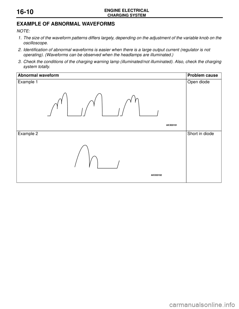
EXAMPLE OF ABNORMAL WAVEFORMS
NOTE: .
1. The size of the waveform patterns differs largely, depending on the adjustment of the variable knob on the
oscilloscope.
2. Identification of abnormal waveforms is easier when there is a large output current (regulator is not
operating). (Waveforms can be observed when the headlamps are illuminated.)
3. Check the conditions of the charging warning lamp (illuminated/not illuminated). Also, check the charging
system totally.
Abnormal waveform Problem cause
Example 1 Open diode
Example 2 Short in diode
AKX00191
AKX00192
Page 121 of 788
EMISSION CONTROL
ENGINE AND EMISSION CONTROL17-13
EXHAUST GAS RECIRCULATION
(EGR) SYSTEM
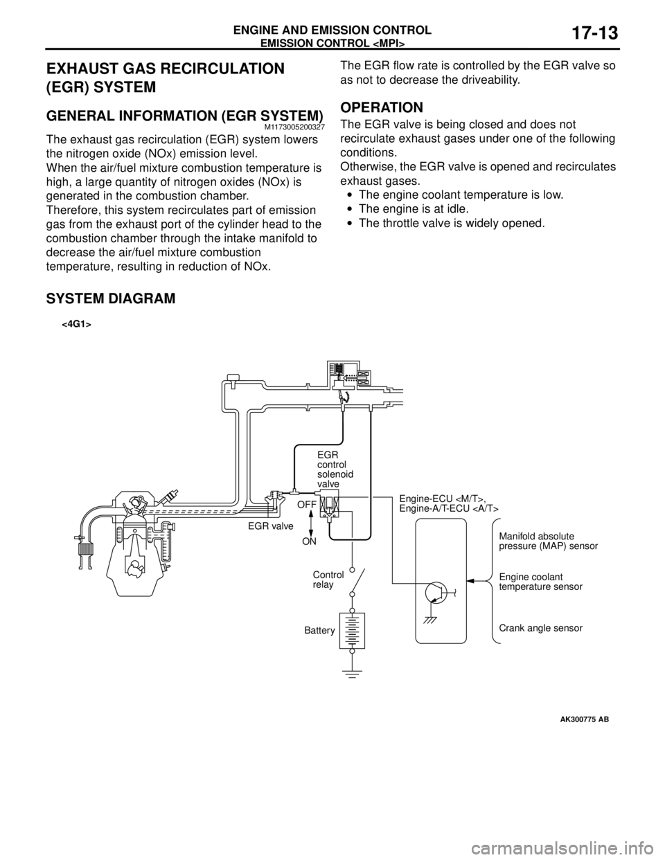
GENERAL INFORMATION (EGR SYSTEM)M1173005200327
The exhaust gas recirculation (EGR) system lowers
the nitrogen oxide (NOx) emission level.
When the air/fuel mixture combustion temperature is
high, a large quantity of nitrogen oxides (NOx) is
generated in the combustion chamber.
Therefore, this system recirculates part of emission
gas from the exhaust port of the cylinder head to the
combustion chamber through the intake manifold to
decrease the air/fuel mixture combustion
temperature, resulting in reduction of NOx.The EGR flow rate is controlled by the EGR valve so
as not to decrease the driveability.
OPERATION
The EGR valve is being closed and does not
recirculate exhaust gases under one of the following
conditions.
Otherwise, the EGR valve is opened and recirculates
exhaust gases.
•The engine coolant temperature is low.
•The engine is at idle.
•The throttle valve is widely opened.
SYSTEM DIAGRAM
AK300775
Manifold absolute
pressure (MAP) sensor Engine-ECU
Engine-A/T-ECU
Engine coolant
temperature sensor
Crank angle sensor EGR
control
solenoid
valve
EGR valveOFF
ON
Control
relay
Battery
AB
<4G1>
Page 178 of 788
CROSSMEMBER
POWER PLANT MOUNT32-8
INSTALLATION SERVICE POINTS
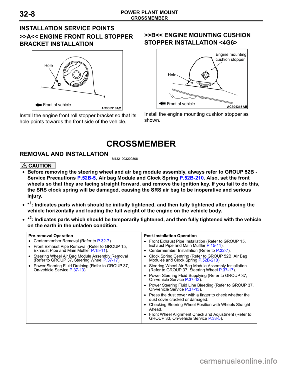
>>A<< ENGINE FRONT ROLL STOPPER
BRACKET INSTALLATION
Install the engine front roll stopper bracket so that its
hole points towards the front side of the vehicle.
>>B<< ENGINE MOUNTING CUSHION
STOPPER INSTALLATION <4G6>
Install the engine mounting cushion stopper as
shown.
CROSSMEMBER
REMOVAL AND INSTALLATIONM1321003200368
CAUTION
•Before removing the steering wheel and air bag module assembly, always refer to GROUP 52B -
Service Precautions P.52B-5, Air bag Module and Clock Spring P.52B-210. Also, set the front
wheels so that they are facing straight forward, and remove the ignition key. If you fail to do this,
the SRS clock spring will be damaged, causing the SRS air bag to be inoperative and serious
injury.
•*
1: Indicates parts which should be initially tightened, and then fully tightened after placing the
vehicle horizontally and loading the full weight of the engine on the vehicle body.
•*
2: Indicates parts which should be temporarily tightened, and then fully tightened with the vehicle
on the earth in the unladen condition.
AC005918Front of vehicleHoleACAC304315ABFront of vehicle
HoleEngine mounting
cushion stopper
Pre-removal Operation
•Centermember Removal (Refer to P.32-7).
•Front Exhaust Pipe Removal (Refer to GROUP 15,
Exhaust Pipe and Main Muffler P.15-11).
•Steering Wheel Air Bag Module Assembly Removal
(Refer to GROUP 37, Steering Wheel P.37-17).
•Power Steering Fluid Draining (Refer to GROUP 37,
On-vehicle Service P.37-13).Post-installation Operation
•Front Exhaust Pipe Installation (Refer to GROUP 15,
Exhaust Pipe and Main Muffler P.15-11).
•Centermember Installation (Refer to P.32-7).
•Clock Spring Centring (Refer to GROUP 52B, Air Bag
Modules and Clock Spring P.52B-210).
•Steering Wheel Air Bag Module Assembly Installation
(Refer to GROUP 37, Steering Wheel P.37-17).
•Power Steering Fluid Supplying (Refer to GROUP 37,
On-vehicle Service P.37-13).
•Power Steering Fluid Line Bleeding (Refer to GROUP 37,
On-vehicle Service P.37-13).
•Press the dust cover with a finger to check whether the
dust cover cracked or damaged.
•Checking Steering Wheel Position with Wheels Straight
Ahead.
•Front Wheel Alignment Check and Adjustment (Refer to
GROUP 33, On-vehicle Service P.33-5).
Page 196 of 788
STABILIZER BAR
FRONT SUSPENSION33-14
STABILIZER BAR
REMOVAL AND INSTALLATIONM1332004000468
CAUTION
•Before removing the steering wheel and air bag module assembly, refer to GROUP 52B, Service
Precautions P.52B-5 and Air Bag Module and Clock Spring P.52B-210. Also, put the front wheels in
straight-ahead position. Failure to do so may damage the SRS clock spring and render the SRS air
bag inoperative, which results serious driver injury.
•
*: Indicates parts which should be initially tightened, and then fully tightened after placing the
vehicle horizontally and loading the full weight of the engine on the vehicle body.
Pre-removal Operation
•Steering Wheel and Air Bag Module Assembly Removal
(Comfort: refer to GROUP 37, Steering Wheel
P.37-17/Sport: refer to GROUP 37, Steering Wheel
P.37-19).
•Clock Spring Removal (Refer to GROUP 52B, Air Bag
Modules and Clock Spring P.52B-210).
•Centermember Removal (Refer to GROUP 32, Engine
Roll Stopper, Centermember P.32-7).
•Front Exhaust Pipe Removal (Refer to GROUP 15,
Exhaust Pipe and Main Muffler P.15-11).Post-installation Operation
•Front Exhaust Pipe Installation (Refer to GROUP 15,
Exhaust Pipe and Main Muffler P.15-11).
•Centermember Installation (Refer to GROUP 32, Engine
Roll Stopper, Centermember P.32-7).
•Clock Spring Installation (Refer to GROUP 52B, Air Bag
Modules and Clock Spring P.52B-210).
•Steering Wheel and Air Bag Module Assembly Installation
(Comfort: refer to GROUP 37, Steering Wheel
P.37-17/Sport: refer to GROUP 37, Steering Wheel
P.37-19).
•Check the dust covers for cracks or damage by pushing it
with your finger.
•Checking Steering Wheel Position with Wheels Straight
Ahead
•Front Wheel Alignment Check and Adjustment (Refer to
P.33-5).
Page 245 of 788
ON-VEHICLE SERVICE
POWER STEERING37-11
ON-VEHICLE SERVICE
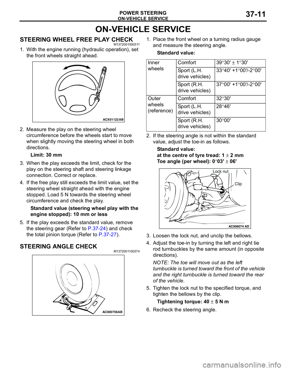
STEERING WHEEL FREE PLAY CHECKM1372001000311
1. With the engine running (hydraulic operation), set
the front wheels straight ahead.
2. Measure the play on the steering wheel
circumference before the wheels start to move
when slightly moving the steering wheel in both
directions.
Limit: 30 mm
3. When the play exceeds the limit, check for the
play on the steering shaft and steering linkage
connection. Correct or replace.
4. If the free play still exceeds the limit value, set the
steering wheel straight ahead with the engine
stopped. Load 5 N towards the steering wheel
circumference and check the play.
Standard value (steering wheel play with the
engine stopped): 10 mm or less
5. If the play exceeds the standard value, remove
the steering gear (Refer to P.37-24) and check
the total pinion torque (Refer to P.37-27).
STEERING ANGLE CHECKM1372001100374
1. Place the front wheel on a turning radius gauge
and measure the steering angle.
Standard value:
2. If the steering angle is not within the standard
value, adjust the toe-in as follows.
Standard value:
at the centre of tyre tread: 1 ± 2 mm
Toe angle (per wheel): 0°03' ± 06'
3. Loosen the lock nut, and unclip the bellows.
4. Adjust the toe-in by turning the left and right tie
rod turnbuckles by the same amount (in opposite
directions).
NOTE: The toe will move out as the left
turnbuckle is turned toward the front of the vehicle
and the right turnbuckle is turned toward the rear
of the vehicle.
5. Tighten the lock nut to the specified torque, and
tighten the bellows by the clip.
Tightening torque: 40 ± 5 N⋅m
6. Recheck the steering angle.
ACX01122
AB
AC000756AB
Inner
wheelsComfort 39°30' ± 1°30'
Sport (L.H.
drive vehicles)33°40' +1°00'/-2°00'
Sport (R.H.
drive vehicles)37°00' +1°00'/-2°00'
Outer
wheels
(reference)Comfort 32°30'
Sport (L.H.
drive vehicles)28°46'
Sport (R.H.
drive vehicles)30°00'
AC006074AD
Lock nut
Clip
Page 246 of 788
ON-VEHICLE SERVICE
POWER STEERING37-12
TIE ROD END BALL JOINT TURNING
TORQUE CHECK
M1372001500297
CAUTION
•Do not remove the tie rod end nut from the
ball joint. Loosen it and use special tool to
avoid possible damage to the ball joint
threads.
•Hang special tool with cord to prevent it from
falling.
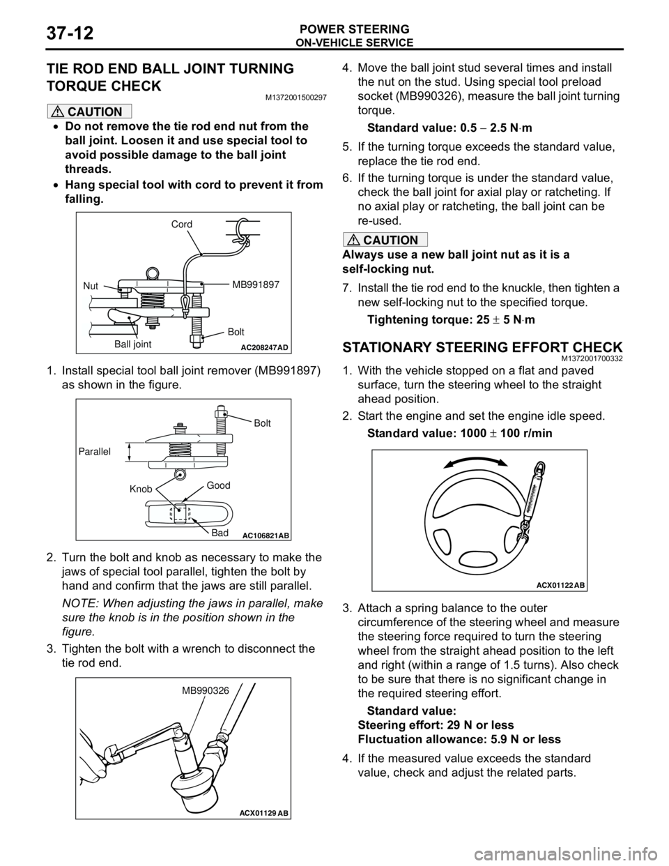
1. Install special tool ball joint remover (MB991897)
as shown in the figure.
2. Turn the bolt and knob as necessary to make the
jaws of special tool parallel, tighten the bolt by
hand and confirm that the jaws are still parallel.
NOTE: When adjusting the jaws in parallel, make
sure the knob is in the position shown in the
figure.
3. Tighten the bolt with a wrench to disconnect the
tie rod end.4. Move the ball joint stud several times and install
the nut on the stud. Using special tool preload
socket (MB990326), measure the ball joint turning
torque.
Standard value: 0.5 − 2.5 N⋅m
5. If the turning torque exceeds the standard value,
replace the tie rod end.
6. If the turning torque is under the standard value,
check the ball joint for axial play or ratcheting. If
no axial play or ratcheting, the ball joint can be
re-used.
CAUTION
Always use a new ball joint nut as it is a
self-locking nut.
7. Install the tie rod end to the knuckle, then tighten a
new self-locking nut to the specified torque.
Tightening torque: 25 ± 5 N⋅m
STATIONARY STEERING EFFORT CHECKM1372001700332
1. With the vehicle stopped on a flat and paved
surface, turn the steering wheel to the straight
ahead position.
2. Start the engine and set the engine idle speed.
Standard value: 1000 ± 100 r/min
3. Attach a spring balance to the outer
circumference of the steering wheel and measure
the steering force required to turn the steering
wheel from the straight ahead position to the left
and right (within a range of 1.5 turns). Also check
to be sure that there is no significant change in
the required steering effort.
Standard value:
Steering effort: 29 N or less
Fluctuation allowance: 5.9 N or less
4. If the measured value exceeds the standard
value, check and adjust the related parts.
AC208247AD
Cord
BoltMB991897
Nut
Ball joint
AC106821
Knob ParallelBolt
Good
Bad
AB
ACX01129
AB
MB990326
ACX01122
AB