Head assembly MITSUBISHI LANCER 2005 Workshop Manual
[x] Cancel search | Manufacturer: MITSUBISHI, Model Year: 2005, Model line: LANCER, Model: MITSUBISHI LANCER 2005Pages: 788, PDF Size: 45.98 MB
Page 59 of 788
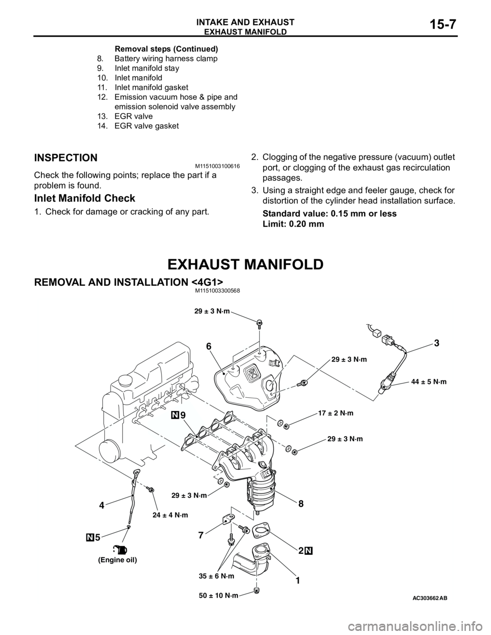
EXHAUST MANIFOLD
INTAKE AND EXHAUST15-7
INSPECTIONM1151003100616
Check the following points; replace the part if a
problem is found.
Inlet Manifold Check
1. Check for damage or cracking of any part.2. Clogging of the negative pressure (vacuum) outlet
port, or clogging of the exhaust gas recirculation
passages.
3. Using a straight edge and feeler gauge, check for
distortion of the cylinder head installation surface.
Standard value: 0.15 mm or less
Limit: 0.20 mm
EXHAUST MANIFOLD
REMOVAL AND INSTALLATION <4G1>M1151003300568
8. Battery wiring harness clamp
9. Inlet manifold stay
10. Inlet manifold
11. Inlet manifold gasket
12. Emission vacuum hose & pipe and
emission solenoid valve assembly
13. EGR valve
14. EGR valve gasketRemoval steps (Continued)
AC30366250 ± 10 N·m 24 ± 4 N·m
35 ± 6 N·m17 ± 2 N·m 29 ± 3 N·m
N
3
7
12 4
N
6
8
44 ± 5 N·m
AB
9
5N
29 ± 3 N·m
29 ± 3 N·m
29 ± 3 N·m
(Engine oil)
Page 178 of 788
CROSSMEMBER
POWER PLANT MOUNT32-8
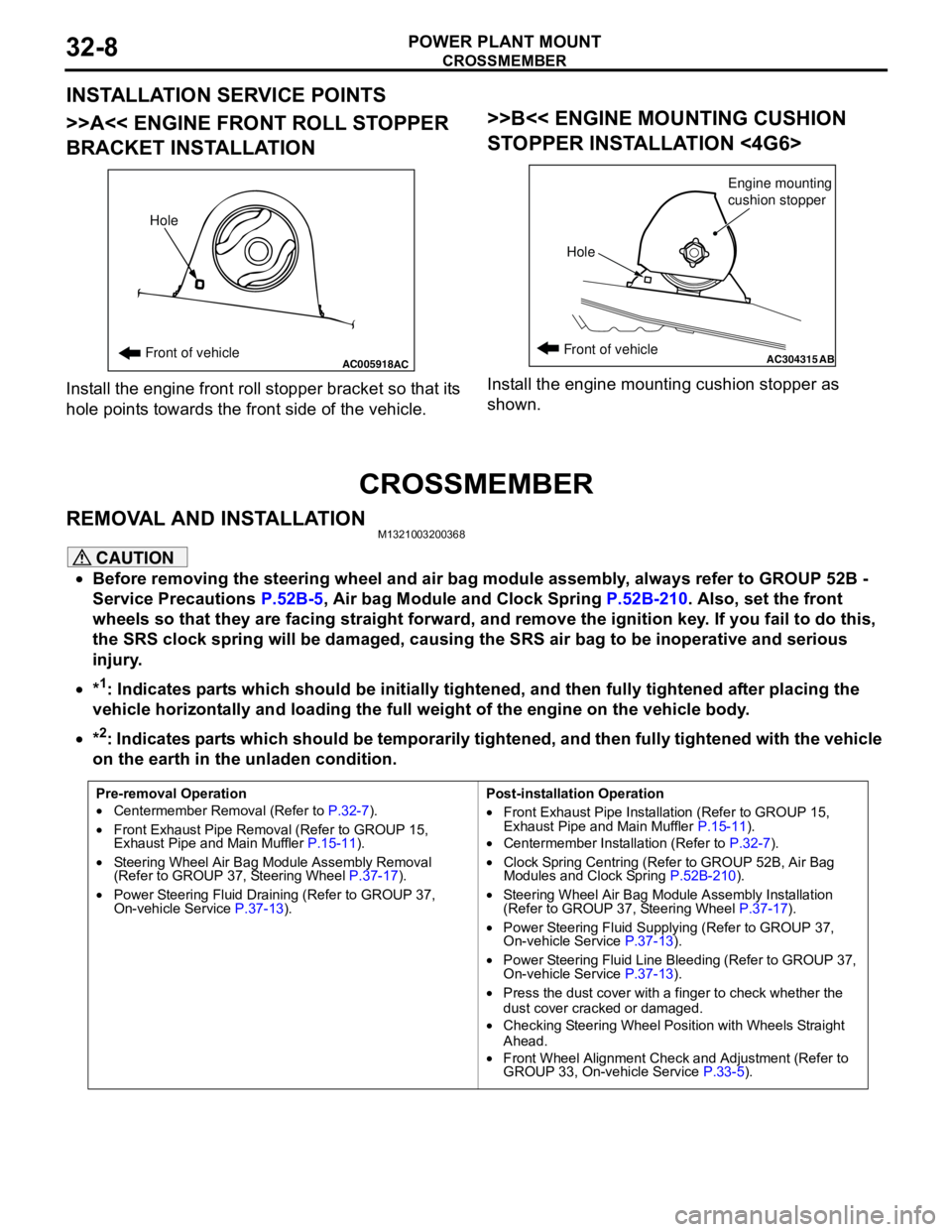
INSTALLATION SERVICE POINTS
>>A<< ENGINE FRONT ROLL STOPPER
BRACKET INSTALLATION
Install the engine front roll stopper bracket so that its
hole points towards the front side of the vehicle.
>>B<< ENGINE MOUNTING CUSHION
STOPPER INSTALLATION <4G6>
Install the engine mounting cushion stopper as
shown.
CROSSMEMBER
REMOVAL AND INSTALLATIONM1321003200368
CAUTION
•Before removing the steering wheel and air bag module assembly, always refer to GROUP 52B -
Service Precautions P.52B-5, Air bag Module and Clock Spring P.52B-210. Also, set the front
wheels so that they are facing straight forward, and remove the ignition key. If you fail to do this,
the SRS clock spring will be damaged, causing the SRS air bag to be inoperative and serious
injury.
•*
1: Indicates parts which should be initially tightened, and then fully tightened after placing the
vehicle horizontally and loading the full weight of the engine on the vehicle body.
•*
2: Indicates parts which should be temporarily tightened, and then fully tightened with the vehicle
on the earth in the unladen condition.
AC005918Front of vehicleHoleACAC304315ABFront of vehicle
HoleEngine mounting
cushion stopper
Pre-removal Operation
•Centermember Removal (Refer to P.32-7).
•Front Exhaust Pipe Removal (Refer to GROUP 15,
Exhaust Pipe and Main Muffler P.15-11).
•Steering Wheel Air Bag Module Assembly Removal
(Refer to GROUP 37, Steering Wheel P.37-17).
•Power Steering Fluid Draining (Refer to GROUP 37,
On-vehicle Service P.37-13).Post-installation Operation
•Front Exhaust Pipe Installation (Refer to GROUP 15,
Exhaust Pipe and Main Muffler P.15-11).
•Centermember Installation (Refer to P.32-7).
•Clock Spring Centring (Refer to GROUP 52B, Air Bag
Modules and Clock Spring P.52B-210).
•Steering Wheel Air Bag Module Assembly Installation
(Refer to GROUP 37, Steering Wheel P.37-17).
•Power Steering Fluid Supplying (Refer to GROUP 37,
On-vehicle Service P.37-13).
•Power Steering Fluid Line Bleeding (Refer to GROUP 37,
On-vehicle Service P.37-13).
•Press the dust cover with a finger to check whether the
dust cover cracked or damaged.
•Checking Steering Wheel Position with Wheels Straight
Ahead.
•Front Wheel Alignment Check and Adjustment (Refer to
GROUP 33, On-vehicle Service P.33-5).
Page 196 of 788
STABILIZER BAR
FRONT SUSPENSION33-14
STABILIZER BAR
REMOVAL AND INSTALLATIONM1332004000468
CAUTION
•Before removing the steering wheel and air bag module assembly, refer to GROUP 52B, Service
Precautions P.52B-5 and Air Bag Module and Clock Spring P.52B-210. Also, put the front wheels in
straight-ahead position. Failure to do so may damage the SRS clock spring and render the SRS air
bag inoperative, which results serious driver injury.
•
*: Indicates parts which should be initially tightened, and then fully tightened after placing the
vehicle horizontally and loading the full weight of the engine on the vehicle body.
Pre-removal Operation
•Steering Wheel and Air Bag Module Assembly Removal
(Comfort: refer to GROUP 37, Steering Wheel
P.37-17/Sport: refer to GROUP 37, Steering Wheel
P.37-19).
•Clock Spring Removal (Refer to GROUP 52B, Air Bag
Modules and Clock Spring P.52B-210).
•Centermember Removal (Refer to GROUP 32, Engine
Roll Stopper, Centermember P.32-7).
•Front Exhaust Pipe Removal (Refer to GROUP 15,
Exhaust Pipe and Main Muffler P.15-11).Post-installation Operation
•Front Exhaust Pipe Installation (Refer to GROUP 15,
Exhaust Pipe and Main Muffler P.15-11).
•Centermember Installation (Refer to GROUP 32, Engine
Roll Stopper, Centermember P.32-7).
•Clock Spring Installation (Refer to GROUP 52B, Air Bag
Modules and Clock Spring P.52B-210).
•Steering Wheel and Air Bag Module Assembly Installation
(Comfort: refer to GROUP 37, Steering Wheel
P.37-17/Sport: refer to GROUP 37, Steering Wheel
P.37-19).
•Check the dust covers for cracks or damage by pushing it
with your finger.
•Checking Steering Wheel Position with Wheels Straight
Ahead
•Front Wheel Alignment Check and Adjustment (Refer to
P.33-5).
Page 251 of 788
STEERING WHEEL
POWER STEERING37-17
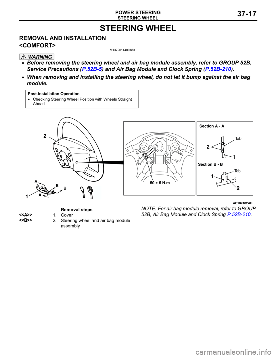
STEERING WHEEL
REMOVAL AND INSTALLATION
M1372011400183
WARNING
•Before removing the steering wheel and air bag module assembly, refer to GROUP 52B,
Service Precautions (P.52B-5) and Air Bag Module and Clock Spring (P.52B-210).
•When removing and installing the steering wheel, do not let it bump against the air bag
module.
NOTE: For air bag module removal, refer to GROUP
52B, Air Bag Module and Clock Spring P.52B-210.
Post-installation Operation
•Checking Steering Wheel Position with Wheels Straight
Ahead
AC107402AB
50 ± 5 N·m
1 2
2
1
12
A
AB
BTa b
Ta b Section A - A
Section B - B
Removal steps
<>1. Cover
<>2. Steering wheel and air bag module
assembly
Page 253 of 788
STEERING WHEEL
POWER STEERING37-19
REMOVAL AND INSTALLATION
WARNING
•Before removing the steering wheel and air bag module assembly, refer to GROUP 52B,
Service Precautions (P.52B-5) and Air Bag Module and Clock Spring (P.52B-210).
•When removing and installing the steering wheel, do not let it bump against the air bag
module.
NOTE: For air bag module removal, refer to GROUP
52B, Air Bag Module and Clock Spring P.52B-210.
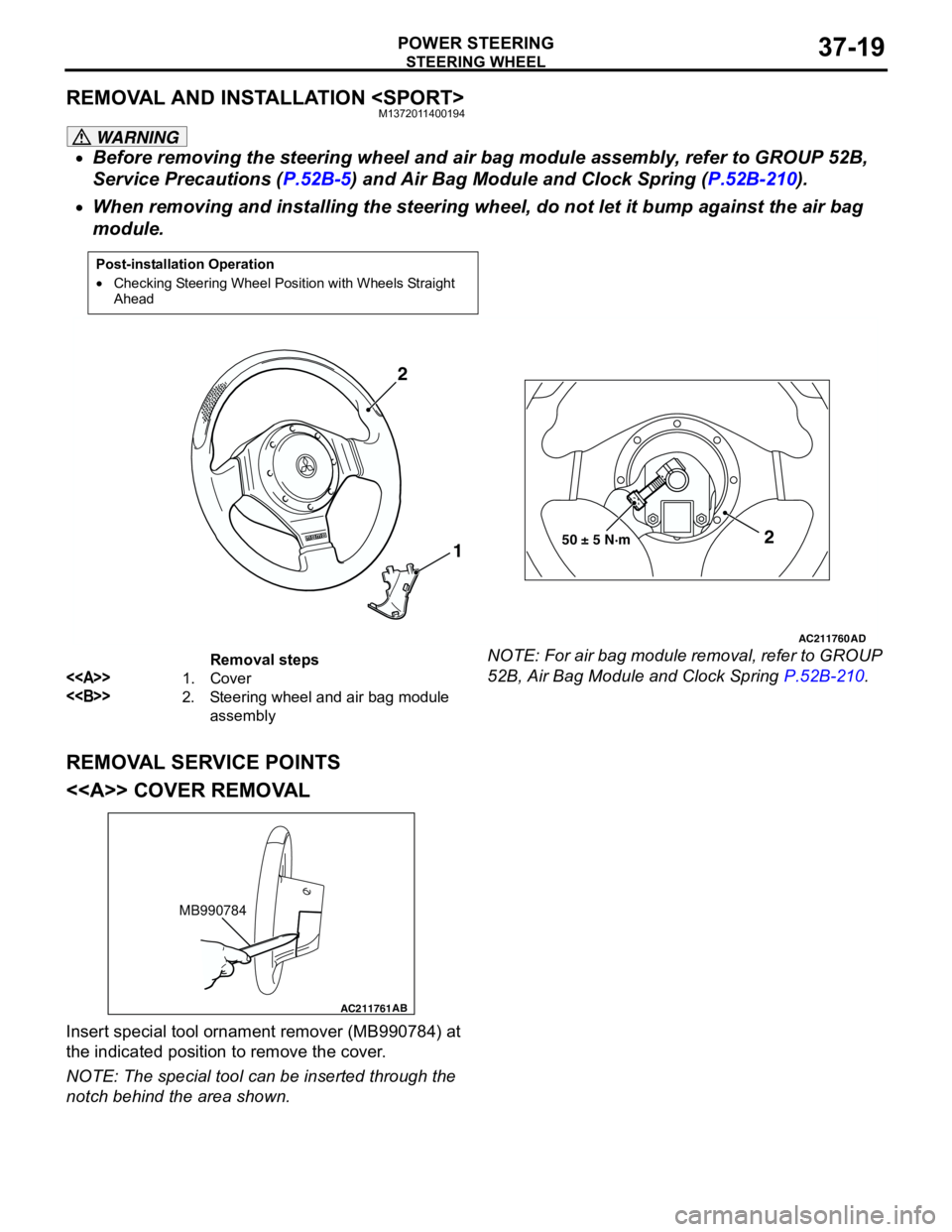
REMOVAL SERVICE POINTS
<> COVER REMOVAL
Insert special tool ornament remover (MB990784) at
the indicated position to remove the cover.
NOTE: The special tool can be inserted through the
notch behind the area shown.
Post-installation Operation
•Checking Steering Wheel Position with Wheels Straight
Ahead
AC211760
AD
50 ± 5 N·m2
1 2
Removal steps
<>1. Cover
<>2. Steering wheel and air bag module
assembly
AC211761AB
MB990784
Page 257 of 788
Page 258 of 788
POWER STEERING GEAR BOX AND LINKAGE
POWER STEERING37-24
POWER STEERING GEAR BOX AND LINKAGE
REMOVAL AND INSTALLATIONM1372010900237
WARNING
Before removing the steering gear, refer to GROUP 52B, Service Precautions (P.52B-5) and
Air Bag Module and Clock Spring (P.52B-210). Centre the front wheels. Failure to do so may
damage the SRS clock spring and render the SRS system inoperative, risking serious injury.
Pre-removal Operation
•Power Steering Fluid Draining (Refer to P.37-13.)Post-installation Operation
•Check the dust cover for cracks or damage by pushing it
with your finger.
•Power Steering Fluid Supplying (Refer to P.37-13.)
•Power Steering Fluid Line Bleeding (Refer to P.37-13.)
•Checking Steering Wheel Position with Wheels Straight
Ahead.
•Front Wheel Alignment Adjustment (Refer to GROUP 33,
On-vehicle Service − Front Wheel Alignment Check and
Adjustment P.33-5.)
AC304920
AB
57 ± 7 N·m
15 ± 3 N·m 70 ± 10 N·m
7
3 8
5
6
9
1024
1
12 ± 2 N·m
12 ± 2 N·m
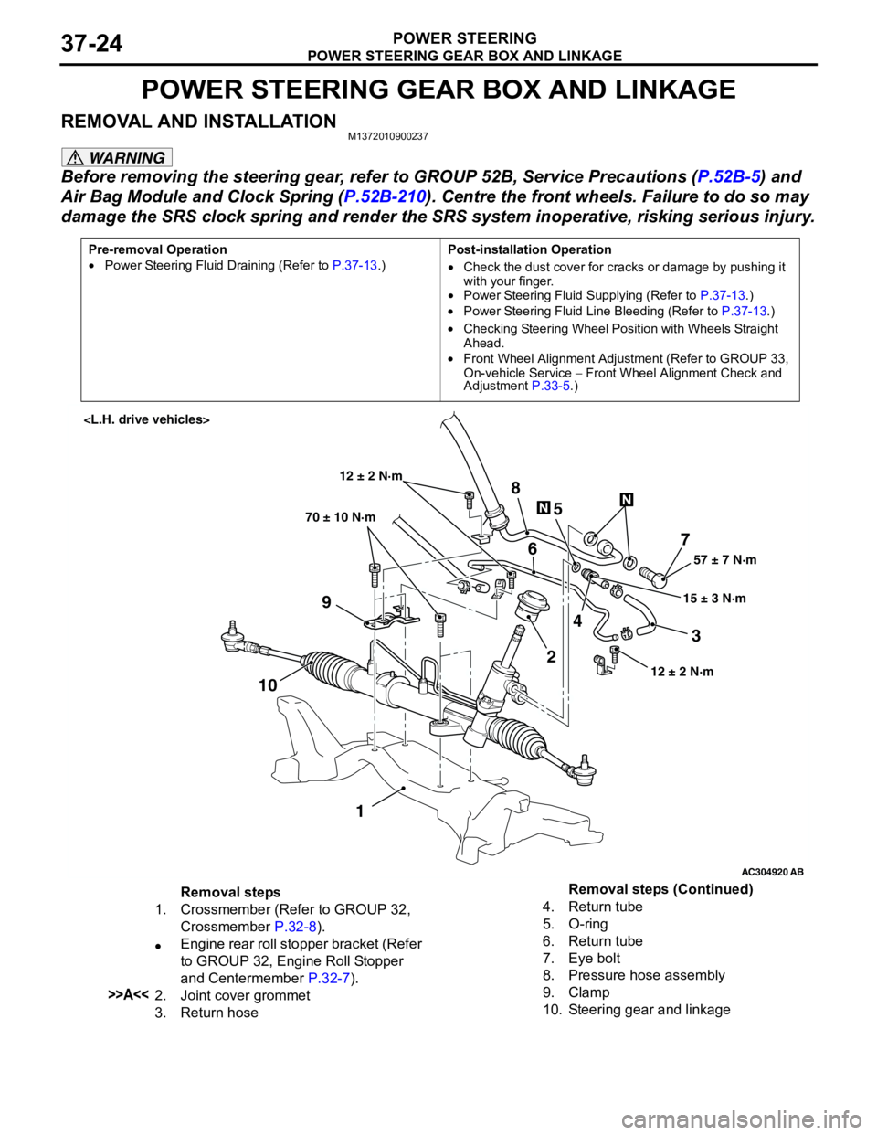
Removal steps
1. Crossmember (Refer to GROUP 32,
Crossmember P.32-8).
•Engine rear roll stopper bracket (Refer
to GROUP 32, Engine Roll Stopper
and Centermember P.32-7).
>>A<<2. Joint cover grommet
3. Return hose4. Return tube
5. O-ring
6. Return tube
7. Eye bolt
8. Pressure hose assembly
9. Clamp
10. Steering gear and linkageRemoval steps (Continued)
Page 294 of 788
WINDOW GLASS
BODY42-16
REAR WINDOW GLASS
REMOVAL AND INSTALLATIONM1422001600111
Pre-removal and Post-installation Operation
•High-mounted Stop Lamp Assembly Removal and
Installation
54A, High-Mounted Stop Lamp P.54A-81.)
•Rear Pillar Trim and Rear Shelf Trim Removal and
Installation (Refer to GROUP 52A, Trims P.52A-11.)
•Headlining Removal and Installation (Refer to GROUP
52A, Headlining P.52A-21.)
Y0500AU
Y0502AUY0501AU
Y0564AU
AC006056
11 7
7
AB
6
25
4 9
7 3
N
2N
2N
N
4N
N
3N3N
NN
2N
Ceramic line
Mark
Apply the primer and
adhesive along the
fictitious lines (seal line)
between each of
the marks.Section A – A
Section B – B
Seal line
centre
Primer
8N
10N
Adhesive: 3M ATD Part No. 8609 Super Fast Urethane Auto Glass Sealant or equivalent and
3M ATD Part No. 8608 Super Fast Urethane Primer or equivalent
16 mm
A
A
B
B
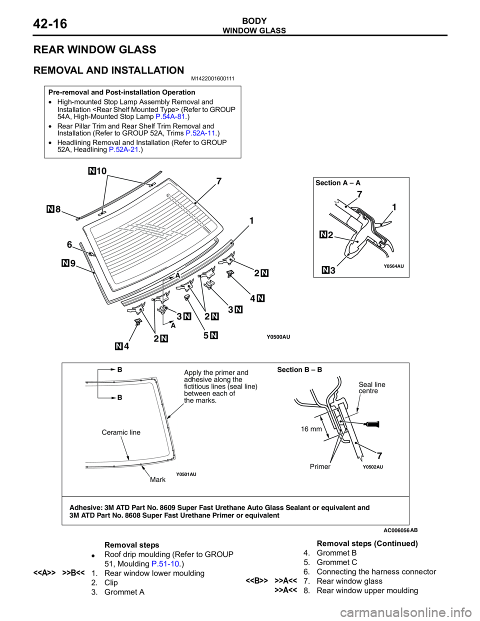
Removal steps
•Roof drip moulding (Refer to GROUP
51, Moulding P.51-10.)
<> >>B<<1. Rear window lower moulding
2. Clip
3. Grommet A4. Grommet B
5. Grommet C
6. Connecting the harness connector<> >>A<<7. Rear window glass
>>A<<8. Rear window upper mouldingRemoval steps (Continued)
Page 339 of 788
51-1
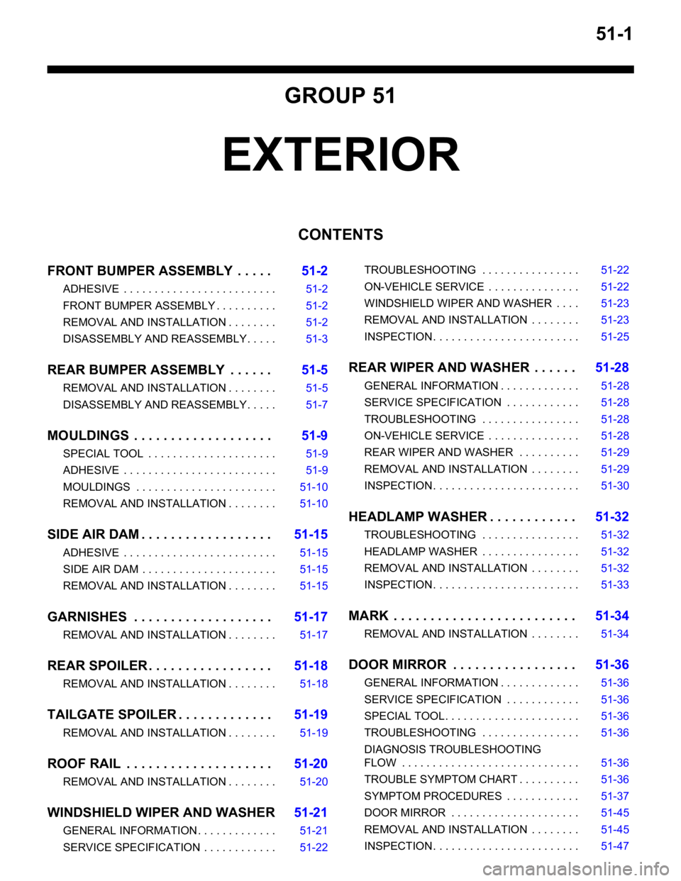
GROUP 51
EXTERIOR
CONTENTS
FRONT BUMPER ASSEMBLY . . . . .51-2
ADHESIVE . . . . . . . . . . . . . . . . . . . . . . . . . 51-2
FRONT BUMPER ASSEMBLY . . . . . . . . . . 51-2
REMOVAL AND INSTALLATION . . . . . . . . 51-2
DISASSEMBLY AND REASSEMBLY . . . . . 51-3
REAR BUMPER ASSEMBLY . . . . . .51-5
REMOVAL AND INSTALLATION . . . . . . . . 51-5
DISASSEMBLY AND REASSEMBLY . . . . . 51-7
MOULDINGS . . . . . . . . . . . . . . . . . . .51-9
SPECIAL TOOL . . . . . . . . . . . . . . . . . . . . . 51-9
ADHESIVE . . . . . . . . . . . . . . . . . . . . . . . . . 51-9
MOULDINGS . . . . . . . . . . . . . . . . . . . . . . . 51-10
REMOVAL AND INSTALLATION . . . . . . . . 51-10
SIDE AIR DAM . . . . . . . . . . . . . . . . . .51-15
ADHESIVE . . . . . . . . . . . . . . . . . . . . . . . . . 51-15
SIDE AIR DAM . . . . . . . . . . . . . . . . . . . . . . 51-15
REMOVAL AND INSTALLATION . . . . . . . . 51-15
GARNISHES . . . . . . . . . . . . . . . . . . .51-17
REMOVAL AND INSTALLATION . . . . . . . . 51-17
REAR SPOILER . . . . . . . . . . . . . . . . .51-18
REMOVAL AND INSTALLATION . . . . . . . . 51-18
TAILGATE SPOILER . . . . . . . . . . . . .51-19
REMOVAL AND INSTALLATION . . . . . . . . 51-19
ROOF RAIL . . . . . . . . . . . . . . . . . . . .51-20
REMOVAL AND INSTALLATION . . . . . . . . 51-20
WINDSHIELD WIPER AND WASHER51-21
GENERAL INFORMATION . . . . . . . . . . . . . 51-21
SERVICE SPECIFICATION . . . . . . . . . . . . 51-22TROUBLESHOOTING . . . . . . . . . . . . . . . . 51-22
ON-VEHICLE SERVICE . . . . . . . . . . . . . . . 51-22
WINDSHIELD WIPER AND WASHER . . . . 51-23
REMOVAL AND INSTALLATION . . . . . . . . 51-23
INSPECTION . . . . . . . . . . . . . . . . . . . . . . . . 51-25
REAR WIPER AND WASHER . . . . . .51-28
GENERAL INFORMATION . . . . . . . . . . . . . 51-28
SERVICE SPECIFICATION . . . . . . . . . . . . 51-28
TROUBLESHOOTING . . . . . . . . . . . . . . . . 51-28
ON-VEHICLE SERVICE . . . . . . . . . . . . . . . 51-28
REAR WIPER AND WASHER . . . . . . . . . . 51-29
REMOVAL AND INSTALLATION . . . . . . . . 51-29
INSPECTION . . . . . . . . . . . . . . . . . . . . . . . . 51-30
HEADLAMP WASHER . . . . . . . . . . . .51-32
TROUBLESHOOTING . . . . . . . . . . . . . . . . 51-32
HEADLAMP WASHER . . . . . . . . . . . . . . . . 51-32
REMOVAL AND INSTALLATION . . . . . . . . 51-32
INSPECTION . . . . . . . . . . . . . . . . . . . . . . . . 51-33
MARK . . . . . . . . . . . . . . . . . . . . . . . . .51-34
REMOVAL AND INSTALLATION . . . . . . . . 51-34
DOOR MIRROR . . . . . . . . . . . . . . . . .51-36
GENERAL INFORMATION . . . . . . . . . . . . . 51-36
SERVICE SPECIFICATION . . . . . . . . . . . . 51-36
SPECIAL TOOL. . . . . . . . . . . . . . . . . . . . . . 51-36
TROUBLESHOOTING . . . . . . . . . . . . . . . . 51-36
DIAGNOSIS TROUBLESHOOTING
FLOW . . . . . . . . . . . . . . . . . . . . . . . . . . . . . 51-36
TROUBLE SYMPTOM CHART . . . . . . . . . . 51-36
SYMPTOM PROCEDURES . . . . . . . . . . . . 51-37
DOOR MIRROR . . . . . . . . . . . . . . . . . . . . . 51-45
REMOVAL AND INSTALLATION . . . . . . . . 51-45
INSPECTION . . . . . . . . . . . . . . . . . . . . . . . . 51-47
Page 371 of 788
HEADLAMP WASHER
EXTERIOR51-33
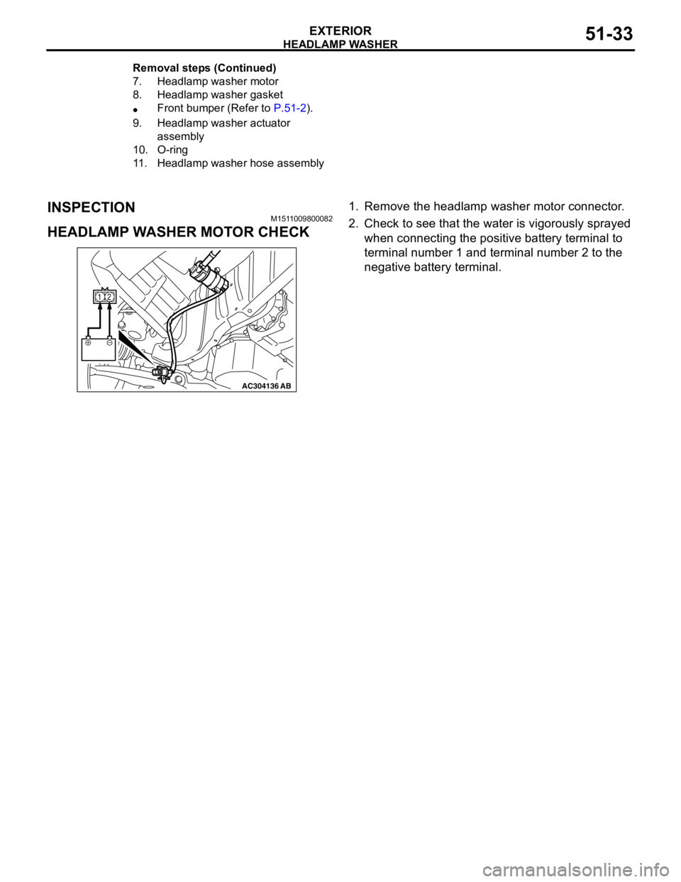
INSPECTIONM1511009800082
HEADLAMP WASHER MOTOR CHECK
1. Remove the headlamp washer motor connector.
2. Check to see that the water is vigorously sprayed
when connecting the positive battery terminal to
terminal number 1 and terminal number 2 to the
negative battery terminal.
7. Headlamp washer motor
8. Headlamp washer gasket
•Front bumper (Refer to P.51-2).
9. Headlamp washer actuator
assembly
10. O-ring
11. Headlamp washer hose assembly Removal steps (Continued)
AC304136AB
12