Ignition assembly MITSUBISHI LANCER 2005 Workshop Manual
[x] Cancel search | Manufacturer: MITSUBISHI, Model Year: 2005, Model line: LANCER, Model: MITSUBISHI LANCER 2005Pages: 788, PDF Size: 45.98 MB
Page 65 of 788
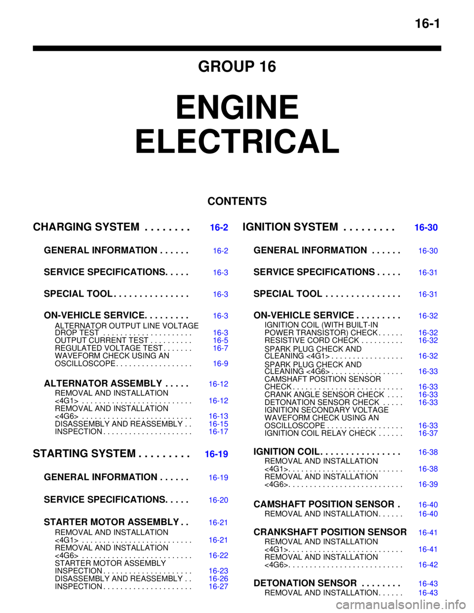
16-1
GROUP 16
ENGINE
ELECTRICAL
CONTENTS
CHARGING SYSTEM . . . . . . . .
16-2
GENERAL INFORMATION . . . . . .
16-2
SERVICE SPECIFICATIONS. . . . .16-3
SPECIAL TOOL . . . . . . . . . . . . . . .16-3
ON-VEHICLE SERVICE. . . . . . . . .16-3
ALTERNATOR OUTPUT LINE VOLTAGE
DROP TEST . . . . . . . . . . . . . . . . . . . . . 16-3
OUTPUT CURRENT TEST . . . . . . . . . . 16-5
REGULATED VOLTAGE TEST . . . . . . . 16-7
WAVEFORM CHECK USING AN
OSCILLOSCOPE . . . . . . . . . . . . . . . . . . 16-9
ALTERNATOR ASSEMBLY . . . . .16-12
REMOVAL AND INSTALLATION
<4G1> . . . . . . . . . . . . . . . . . . . . . . . . . . 16-12
REMOVAL AND INSTALLATION
<4G6> . . . . . . . . . . . . . . . . . . . . . . . . . . 16-13
DISASSEMBLY AND REASSEMBLY . . 16-15
INSPECTION . . . . . . . . . . . . . . . . . . . . . 16-17
STARTING SYSTEM . . . . . . . . .16-19
GENERAL INFORMATION . . . . . .
16-19
SERVICE SPECIFICATIONS. . . . .16-20
STARTER MOTOR ASSEMBLY . .16-21
REMOVAL AND INSTALLATION
<4G1> . . . . . . . . . . . . . . . . . . . . . . . . . . 16-21
REMOVAL AND INSTALLATION
<4G6> . . . . . . . . . . . . . . . . . . . . . . . . . . 16-22
STARTER MOTOR ASSEMBLY
INSPECTION . . . . . . . . . . . . . . . . . . . . . 16-23
DISASSEMBLY AND REASSEMBLY . . 16-26
INSPECTION . . . . . . . . . . . . . . . . . . . . . 16-27
IGNITION SYSTEM . . . . . . . . . 16-30
GENERAL INFORMATION . . . . . .
16-30
SERVICE SPECIFICATIONS . . . . .16-31
SPECIAL TOOL . . . . . . . . . . . . . . .16-31
ON-VEHICLE SERVICE . . . . . . . . .16-32
IGNITION COIL (WITH BUILT-IN
POWER TRANSISTOR) CHECK . . . . . . 16-32
RESISTIVE CORD CHECK . . . . . . . . . . 16-32
SPARK PLUG CHECK AND
CLEANING <4G1> . . . . . . . . . . . . . . . . . 16-32
SPARK PLUG CHECK AND
CLEANING <4G6> . . . . . . . . . . . . . . . . . 16-33
CAMSHAFT POSITION SENSOR
CHECK . . . . . . . . . . . . . . . . . . . . . . . . . . 16-33
CRANK ANGLE SENSOR CHECK . . . . 16-33
DETONATION SENSOR CHECK . . . . . 16-33
IGNITION SECONDARY VOLTAGE
WAVEFORM CHECK USING AN
OSCILLOSCOPE . . . . . . . . . . . . . . . . . . 16-33
IGNITION COIL RELAY CHECK . . . . . . 16-37
IGNITION COIL . . . . . . . . . . . . . . . .16-38
REMOVAL AND INSTALLATION
<4G1>. . . . . . . . . . . . . . . . . . . . . . . . . . . 16-38
REMOVAL AND INSTALLATION
<4G6>. . . . . . . . . . . . . . . . . . . . . . . . . . . 16-39
CAMSHAFT POSITION SENSOR .16-40
REMOVAL AND INSTALLATION . . . . . . 16-40
CRANKSHAFT POSITION SENSOR16-41
REMOVAL AND INSTALLATION
<4G1>. . . . . . . . . . . . . . . . . . . . . . . . . . . 16-41
REMOVAL AND INSTALLATION
<4G6>. . . . . . . . . . . . . . . . . . . . . . . . . . . 16-42
DETONATION SENSOR . . . . . . . .16-43
REMOVAL AND INSTALLATION . . . . . . 16-43
Page 106 of 788
IGNITION SYSTEM
ENGINE ELECTRICAL16-42
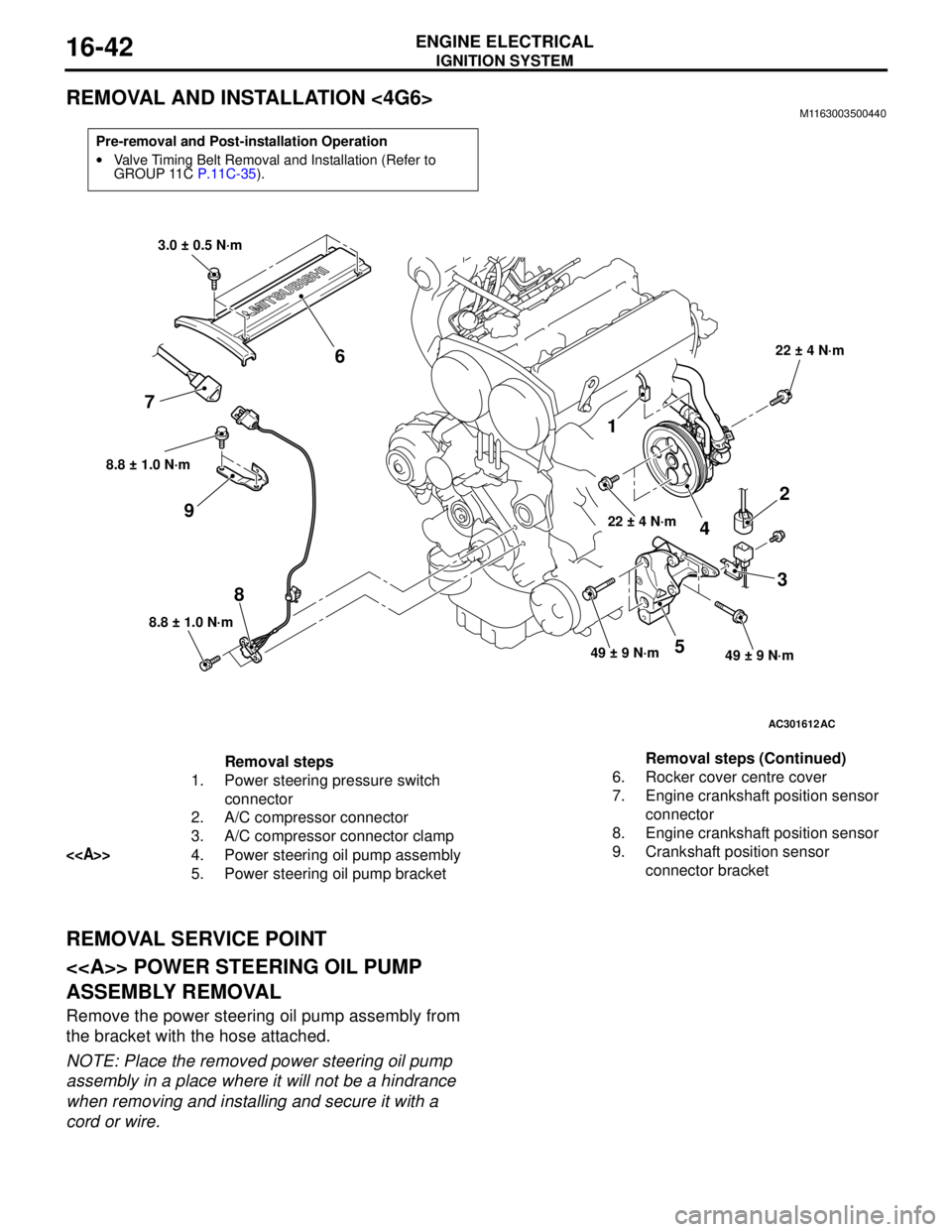
REMOVAL AND INSTALLATION <4G6>M1163003500440
REMOVAL SERVICE POINT
<> POWER STEERING OIL PUMP
ASSEMBLY REMOVAL
Remove the power steering oil pump assembly from
the bracket with the hose attached.
NOTE: Place the removed power steering oil pump
assembly in a place where it will not be a hindrance
when removing and installing and secure it with a
cord or wire.
Pre-removal and Post-installation Operation
•Valve Timing Belt Removal and Installation (Refer to
GROUP 11C P.11C-35).
AC301612
8.8 ± 1.0 N·m
8
8.8 ± 1.0 N·m
9
1
22 ± 4 N·m
4
2
3
49 ± 9 N·m49 ± 9 N·m5
22 ± 4 N·m
3.0 ± 0.5 N·m
6
7
AC
Removal steps
1. Power steering pressure switch
connector
2. A/C compressor connector
3. A/C compressor connector clamp
<>4. Power steering oil pump assembly
5. Power steering oil pump bracket6. Rocker cover centre cover
7. Engine crankshaft position sensor
connector
8. Engine crankshaft position sensor
9. Crankshaft position sensor
connector bracket Removal steps (Continued)
Page 178 of 788
CROSSMEMBER
POWER PLANT MOUNT32-8
INSTALLATION SERVICE POINTS
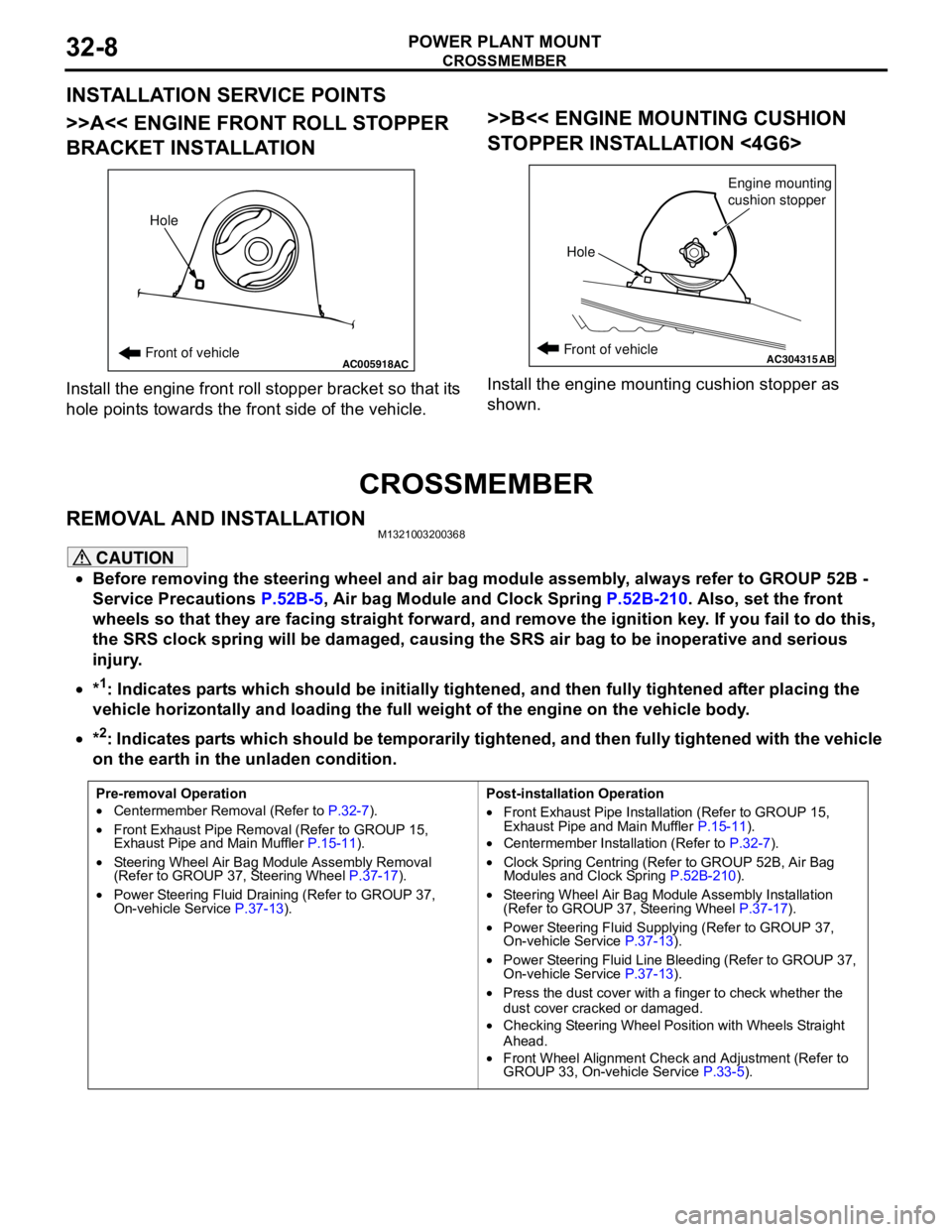
>>A<< ENGINE FRONT ROLL STOPPER
BRACKET INSTALLATION
Install the engine front roll stopper bracket so that its
hole points towards the front side of the vehicle.
>>B<< ENGINE MOUNTING CUSHION
STOPPER INSTALLATION <4G6>
Install the engine mounting cushion stopper as
shown.
CROSSMEMBER
REMOVAL AND INSTALLATIONM1321003200368
CAUTION
•Before removing the steering wheel and air bag module assembly, always refer to GROUP 52B -
Service Precautions P.52B-5, Air bag Module and Clock Spring P.52B-210. Also, set the front
wheels so that they are facing straight forward, and remove the ignition key. If you fail to do this,
the SRS clock spring will be damaged, causing the SRS air bag to be inoperative and serious
injury.
•*
1: Indicates parts which should be initially tightened, and then fully tightened after placing the
vehicle horizontally and loading the full weight of the engine on the vehicle body.
•*
2: Indicates parts which should be temporarily tightened, and then fully tightened with the vehicle
on the earth in the unladen condition.
AC005918Front of vehicleHoleACAC304315ABFront of vehicle
HoleEngine mounting
cushion stopper
Pre-removal Operation
•Centermember Removal (Refer to P.32-7).
•Front Exhaust Pipe Removal (Refer to GROUP 15,
Exhaust Pipe and Main Muffler P.15-11).
•Steering Wheel Air Bag Module Assembly Removal
(Refer to GROUP 37, Steering Wheel P.37-17).
•Power Steering Fluid Draining (Refer to GROUP 37,
On-vehicle Service P.37-13).Post-installation Operation
•Front Exhaust Pipe Installation (Refer to GROUP 15,
Exhaust Pipe and Main Muffler P.15-11).
•Centermember Installation (Refer to P.32-7).
•Clock Spring Centring (Refer to GROUP 52B, Air Bag
Modules and Clock Spring P.52B-210).
•Steering Wheel Air Bag Module Assembly Installation
(Refer to GROUP 37, Steering Wheel P.37-17).
•Power Steering Fluid Supplying (Refer to GROUP 37,
On-vehicle Service P.37-13).
•Power Steering Fluid Line Bleeding (Refer to GROUP 37,
On-vehicle Service P.37-13).
•Press the dust cover with a finger to check whether the
dust cover cracked or damaged.
•Checking Steering Wheel Position with Wheels Straight
Ahead.
•Front Wheel Alignment Check and Adjustment (Refer to
GROUP 33, On-vehicle Service P.33-5).
Page 336 of 788
KEYLESS ENTRY SYSTEM
BODY42-58
7. If you are using two or more transmitters or have
added a second transmitter, the same registration
procedure should be carried out within one minute
after registering the code for the first transmitter.
8. Registration mode will be cancelled under the
following conditions:
•When the secret code for four transmitters has
been registered;•When one minute has passed after registration
mode started;
•When the V.C.I. is disconnected from the
diagnosis connector;
•When the key is removed from the key cylinder;
9. After the registration is completed, remove the
ignition key and close all the doors, and then
check that the keyless entry system operates
normally.
TRANSMITTER
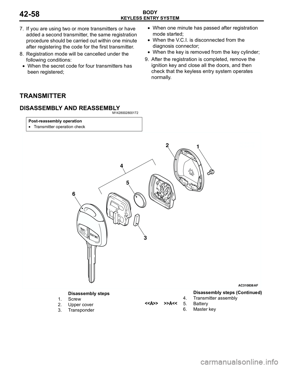
DISASSEMBLY AND REASSEMBLYM1428002800172
Post-reassembly operation
•Transmitter operation check
AC310838AC303199
AC3041181 2
AF
5
3
4
6
Disassembly steps
1. Screw
2. Upper cover
3. Transponder4. Transmitter assembly
<> >>A<<5. Battery
6. Master keyDisassembly steps (Continued)
Page 379 of 788
DOOR MIRROR
EXTERIOR51-41
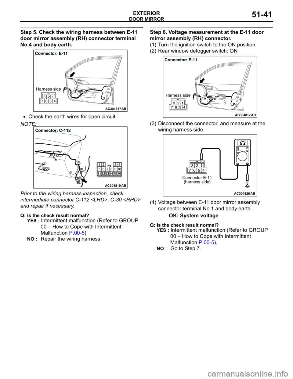
Step 5. Check the wiring harness between E-11
door mirror assembly (RH) connector terminal
No.4 and body earth.
•Check the earth wires for open circuit.
NOTE:
Prior to the wiring harness inspection, check
intermediate connector C-112
and repair if necessary.
Q: Is the check result normal?
YES :
Intermittent malfunction (Refer to GROUP
00 − How to Cope with Intermittent
Malfunction P.00-5).
NO : Repair the wiring harness.
Step 6. Voltage measurement at the E-11 door
mirror assembly (RH) connector.
(1) Turn the ignition switch to the ON position.
(2) Rear window defogger switch: ON
(3) Disconnect the connector, and measure at the
wiring harness side.
(4) Voltage between E-11 door mirror assembly
connector terminal No.1 and body earth
OK: System voltage
Q: Is the check result normal?
YES :
Intermittent malfunction (Refer to GROUP
00 − How to Cope with Intermittent
Malfunction P.00-5).
NO : Go to Step 7.
AC304817
Connector: E-11
Harness side
AB
AC304819
Connector: C-112
AB
AC304817
Connector: E-11
Harness side
AB
AC304826
Connector E-11
(harness side)
AB
Page 382 of 788
DOOR MIRROR
EXTERIOR51-44
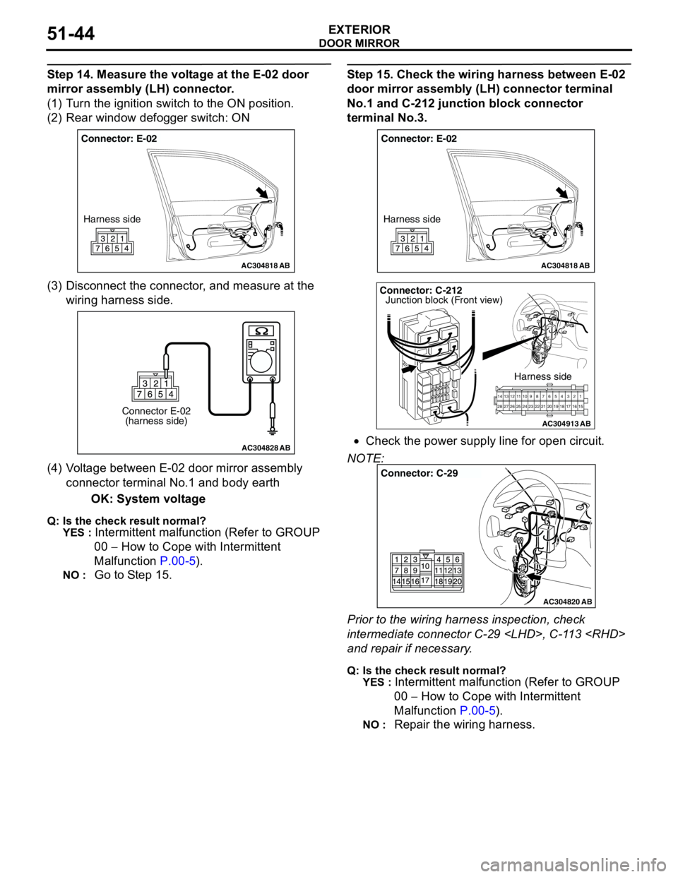
Step 14. Measure the voltage at the E-02 door
mirror assembly (LH) connector.
(1) Turn the ignition switch to the ON position.
(2) Rear window defogger switch: ON
(3) Disconnect the connector, and measure at the
wiring harness side.
(4) Voltage between E-02 door mirror assembly
connector terminal No.1 and body earth
OK: System voltage
Q: Is the check result normal?
YES :
Intermittent malfunction (Refer to GROUP
00 − How to Cope with Intermittent
Malfunction P.00-5).
NO : Go to Step 15.
Step 15. Check the wiring harness between E-02
door mirror assembly (LH) connector terminal
No.1 and C-212 junction block connector
terminal No.3.
•Check the power supply line for open circuit.
NOTE:
Prior to the wiring harness inspection, check
intermediate connector C-29
and repair if necessary.
Q: Is the check result normal?
YES :
Intermittent malfunction (Refer to GROUP
00 − How to Cope with Intermittent
Malfunction P.00-5).
NO : Repair the wiring harness.
AC304818
Connector: E-02
Harness side
AB
AC304828
Connector E-02
(harness side)
AB
AC304818
Connector: E-02
Harness side
AB
AC304913
21716151718 201912345 623 222425282627981011141213
Connector: C-212
Harness side
AB
Junction block (Front view)
AC304820
Connector: C-29
AB
Page 396 of 788
IGNITION SWITCH
CHASSIS ELECTRICAL54A-8
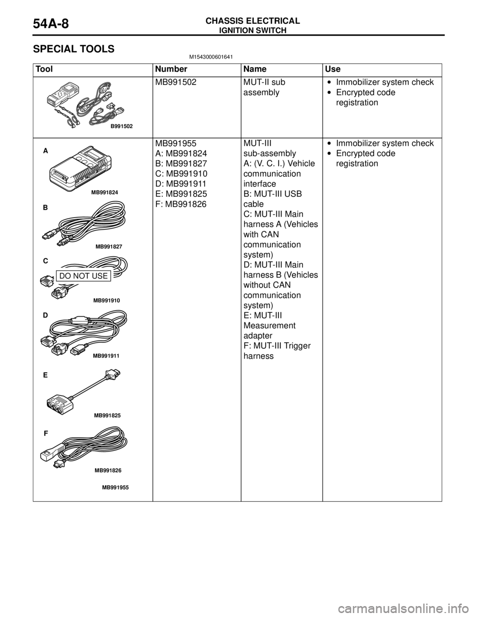
SPECIAL TOOLSM1543000601641
Tool Number Name Use
MB991502 MUT-II sub
assembly•Immobilizer system check
•Encrypted code
registration
MB991955
A: MB991824
B: MB991827
C: MB991910
D: MB991911
E: MB991825
F: MB991826MUT-III
sub-assembly
A: (V. C. I.) Vehicle
communication
interface
B: MUT-III USB
cable
C: MUT-III Main
harness A (Vehicles
with CAN
communication
system)
D: MUT-III Main
harness B (Vehicles
without CAN
communication
system)
E: MUT-III
Measurement
adapter
F: MUT-III Trigger
harness•Immobilizer system check
•Encrypted code
registration
B991502
MB991910
MB991826
MB991955
MB991911
MB991824
MB991827
MB991825
A
B
C
D
E
F
DO NOT USE
Page 415 of 788
IGNITION SWITCH
CHASSIS ELECTRICAL54A-27
IGNITION SWITCH
REMOVAL AND INSTALLATIONM1543002100434
WARNING
•Before removal of the air bag module, refer to GROUP 52B, SRS Service Precautions and
Air Bag Module and Clock Spring P.52B-5.
•When removing and installing the steering wheel, do not let it bump against the air bag
module.
AC304659
2
3
4
67
15
AB
8
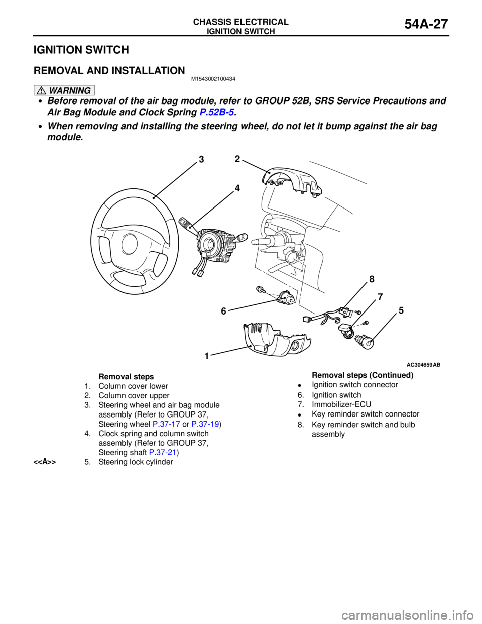
Removal steps
1. Column cover lower
2. Column cover upper
3. Steering wheel and air bag module
assembly (Refer to GROUP 37,
Steering wheel P.37-17 or P.37-19)
4. Clock spring and column switch
assembly (Refer to GROUP 37,
Steering shaft P.37-21)
<>5. Steering lock cylinder•Ignition switch connector
6. Ignition switch
7. Immobilizer-ECU
•Key reminder switch connector
8. Key reminder switch and bulb
assembly Removal steps (Continued)
Page 420 of 788
COMBINATION METER ASSEMBLY
CHASSIS ELECTRICAL54A-32
SYMPTOM PROCEDURES
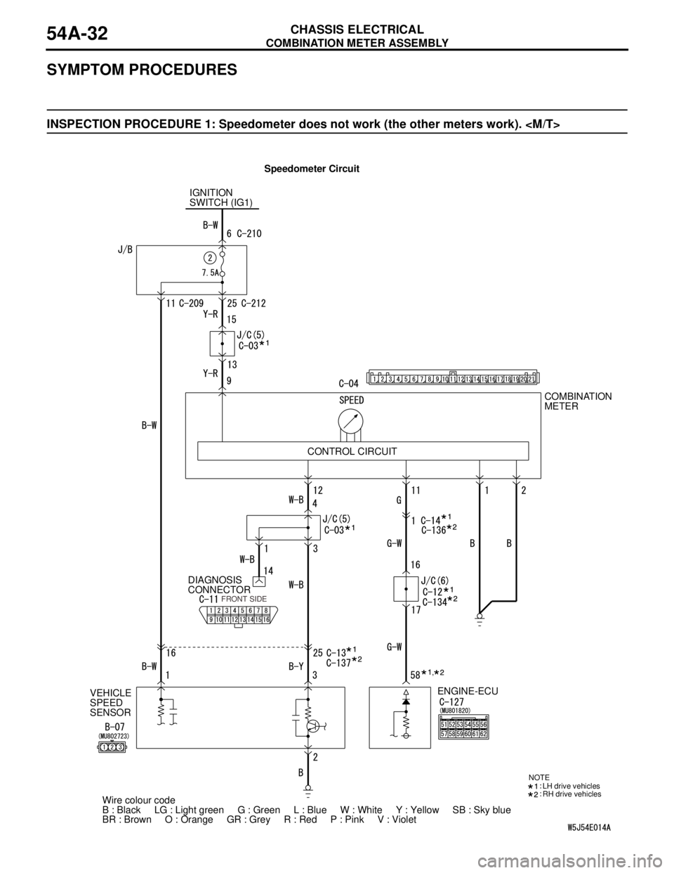
INSPECTION PROCEDURE 1: Speedometer does not work (the other meters work).
Speedometer Circuit
IGNITION
SWITCH (IG1)
VEHICLE
SPEED
SENSORDIAGNOSIS
CONNECTORCOMBINATION
METER
ENGINE-ECU
Wire colour code
B : Black LG : Light green G : Green L : Blue W : White Y : Yellow SB : Sky blue
BR : Brown O : Orange GR : Grey R : Red P : Pink V : Violet CONTROL CIRCUIT
FRONT SIDE
NOTE
LH drive vehicles
RH drive vehicles
,
Page 421 of 788
COMBINATION METER ASSEMBLY
CHASSIS ELECTRICAL54A-33
TECHNICAL DESCRIPTION (COMMENT)
The engine-ECU and its associated components, the
combination meter assembly, the wiring harness, or
the connector(s) may be defective.
TROUBLESHOOTING HINTS
•Malfunction of the vehicle speed sensor
•Malfunction of the engine-ECU
•Malfunction of the combination meter assembly
•The wiring harness or connectors may have
loose, corroded, or damaged terminals, or
terminals pushed back in the connector.
DIAGNOSIS PROCEDURE
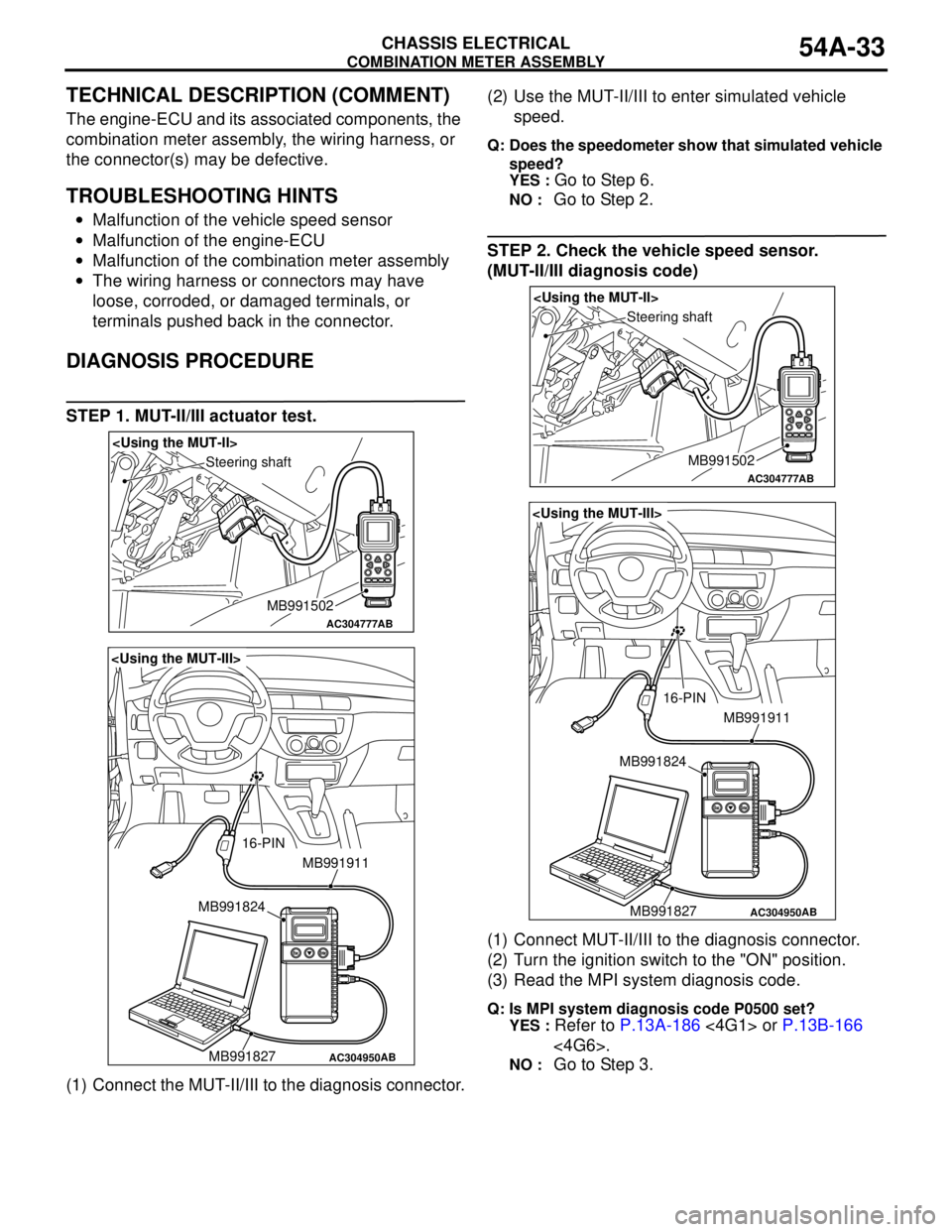
STEP 1. MUT-II/III actuator test.
(1) Connect the MUT-II/III to the diagnosis connector.(2) Use the MUT-II/III to enter simulated vehicle
speed.
Q: Does the speedometer show that simulated vehicle
speed?
YES :
Go to Step 6.
NO : Go to Step 2.
STEP 2. Check the vehicle speed sensor.
(MUT-II/III diagnosis code)
(1) Connect MUT-II/III to the diagnosis connector.
(2) Turn the ignition switch to the "ON" position.
(3) Read the MPI system diagnosis code.
Q: Is MPI system diagnosis code P0500 set?
YES :
Refer to P.13A-186 <4G1> or P.13B-166
<4G6>.
NO : Go to Step 3.
AC304777
Steering shaft
AB
MB991502
AC304950
MB991911
16-PIN
MB991827 MB991824
AB
AC304777
Steering shaft
AB
MB991502
AC304950
MB991911
16-PIN
MB991827 MB991824
AB