Ignition assembly MITSUBISHI LANCER 2005 User Guide
[x] Cancel search | Manufacturer: MITSUBISHI, Model Year: 2005, Model line: LANCER, Model: MITSUBISHI LANCER 2005Pages: 788, PDF Size: 45.98 MB
Page 425 of 788
COMBINATION METER ASSEMBLY
CHASSIS ELECTRICAL54A-37
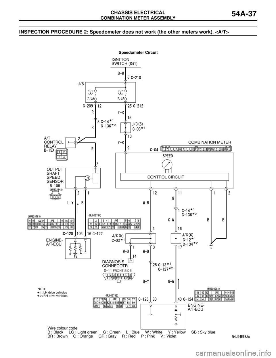
INSPECTION PROCEDURE 2: Speedometer does not work (the other meters work).
IGNITION
SWITCH (IG1)
A/T
CONTROL
RELAY
OUTPUT
SHAFT
SPEED
SENSOR
DIAGNOSIS
CONNECOTR
ENGINE-
A/T-ECUCOMBINATION METER
ENGINE-
A/T-ECU
Wire colour code
B : Black LG : Light green G : Green L : Blue W : White Y : Yellow SB : Sky blue
BR : Brown O : Orange GR : Gray R : Red P : Pink V : Violet
FRONT SIDE
NOTE
LH drive vehicles
RH drive vehicles
CONTROL CIRCUIT
Speedometer Circuit
Page 426 of 788
COMBINATION METER ASSEMBLY
CHASSIS ELECTRICAL54A-38
TECHNICAL DESCRIPTION (COMMENT)
The engine-ECU and its associated components, the
combination meter assembly, the wiring harness, or
the connector(s) may be defective.
TROUBLESHOOTING HINTS
•Malfunction of the vehicle speed sensor
•Malfunction of the engine-ECU
•Malfunction of the combination meter assembly
•The wiring harness or connectors may have
loose, corroded, or damaged terminals, or
terminals pushed back in the connector.
DIAGNOSIS PROCEDURE
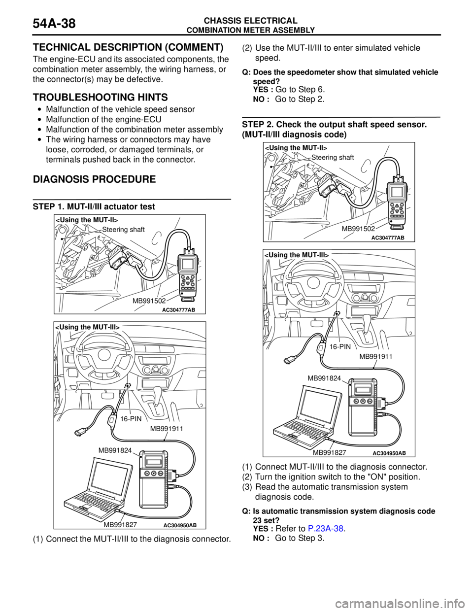
STEP 1. MUT-II/III actuator test
(1) Connect the MUT-II/III to the diagnosis connector.(2) Use the MUT-II/III to enter simulated vehicle
speed.
Q: Does the speedometer show that simulated vehicle
speed?
YES :
Go to Step 6.
NO : Go to Step 2.
STEP 2. Check the output shaft speed sensor.
(MUT-II/III diagnosis code)
(1) Connect MUT-II/III to the diagnosis connector.
(2) Turn the ignition switch to the "ON" position.
(3) Read the automatic transmission system
diagnosis code.
Q: Is automatic transmission system diagnosis code
23 set?
YES :
Refer to P.23A-38.
NO : Go to Step 3.
AC304777
Steering shaft
AB
MB991502
AC304950
MB991911
16-PIN
MB991827 MB991824
AB
AC304777
Steering shaft
AB
MB991502
AC304950
MB991911
16-PIN
MB991827 MB991824
AB
Page 432 of 788
COMBINATION METER ASSEMBLY
CHASSIS ELECTRICAL54A-44
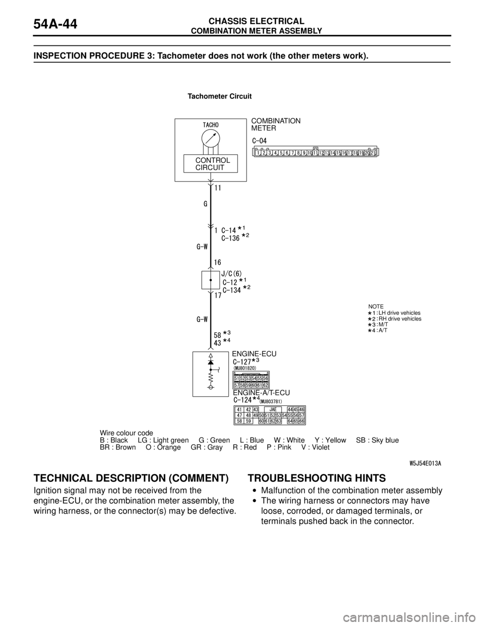
INSPECTION PROCEDURE 3: Tachometer does not work (the other meters work).
TECHNICAL DESCRIPTION (COMMENT)
Ignition signal may not be received from the
engine-ECU, or the combination meter assembly, the
wiring harness, or the connector(s) may be defective.
TROUBLESHOOTING HINTS
•Malfunction of the combination meter assembly
•The wiring harness or connectors may have
loose, corroded, or damaged terminals, or
terminals pushed back in the connector.
ENGINE-ECU
Wire colour code
B : Black LG : Light green G : Green L : Blue W : White Y : Yellow SB : Sky blue
BR : Brown O : Orange GR : Gray R : Red P : Pink V : Violet ENGINE-A/T-ECU
M/T
A/T
NOTELH drive vehicles
RH drive vehicles
COMBINATION
METER
CONTROL
CIRCUIT
Tachometer Circuit
Page 437 of 788
COMBINATION METER ASSEMBLY
CHASSIS ELECTRICAL54A-49
DIAGNOSIS PROCEDURE
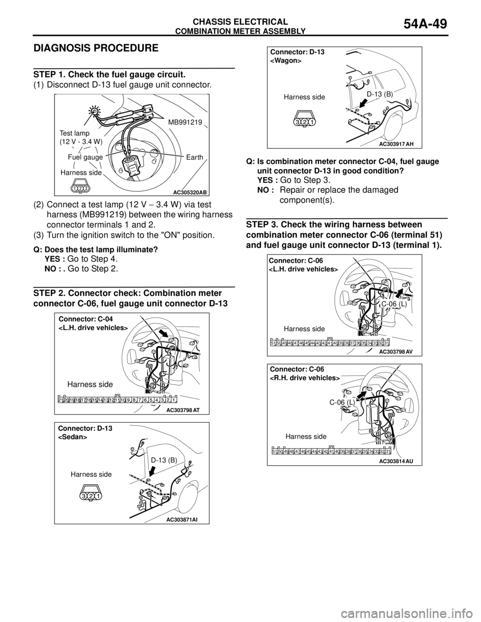
STEP 1. Check the fuel gauge circuit.
(1) Disconnect D-13 fuel gauge unit connector.
(2) Connect a test lamp (12 V − 3.4 W) via test
harness (MB991219) between the wiring harness
connector terminals 1 and 2.
(3) Turn the ignition switch to the "ON" position.
Q: Does the test lamp illuminate?
YES :
Go to Step 4.
NO : . Go to Step 2.
STEP 2. Connector check: Combination meter
connector C-06, fuel gauge unit connector D-13
Q: Is combination meter connector C-04, fuel gauge
unit connector D-13 in good condition?
YES :
Go to Step 3.
NO : Repair or replace the damaged
component(s).
STEP 3. Check the wiring harness between
combination meter connector C-06 (terminal 51)
and fuel gauge unit connector D-13 (terminal 1).
AC305320
AB
Test lamp
(12 V - 3.4 W)
MB991219
Harness side
Fuel gauge
Earth
AC303798
Connector: C-04
Harness side
AT
AC303871
Connector: D-13
Harness sideD-13 (B)
AI
AC303917
D-13 (B) Connector: D-13
Harness side
AH
AC303798
Connector: C-06
Harness side
C-06 (L)
31 32 33 34 35 36 37 38 39 40 41 42 43 44 45 46 47 48 49 50 51
AV
AC303814AU
Connector: C-06
Harness side
31 32 33 34 35 36 37 38 39 40 41 42 43 44 45 46 47 48 49 50 51
C-06 (L)
Page 442 of 788
COMBINATION METER ASSEMBLY
CHASSIS ELECTRICAL54A-54
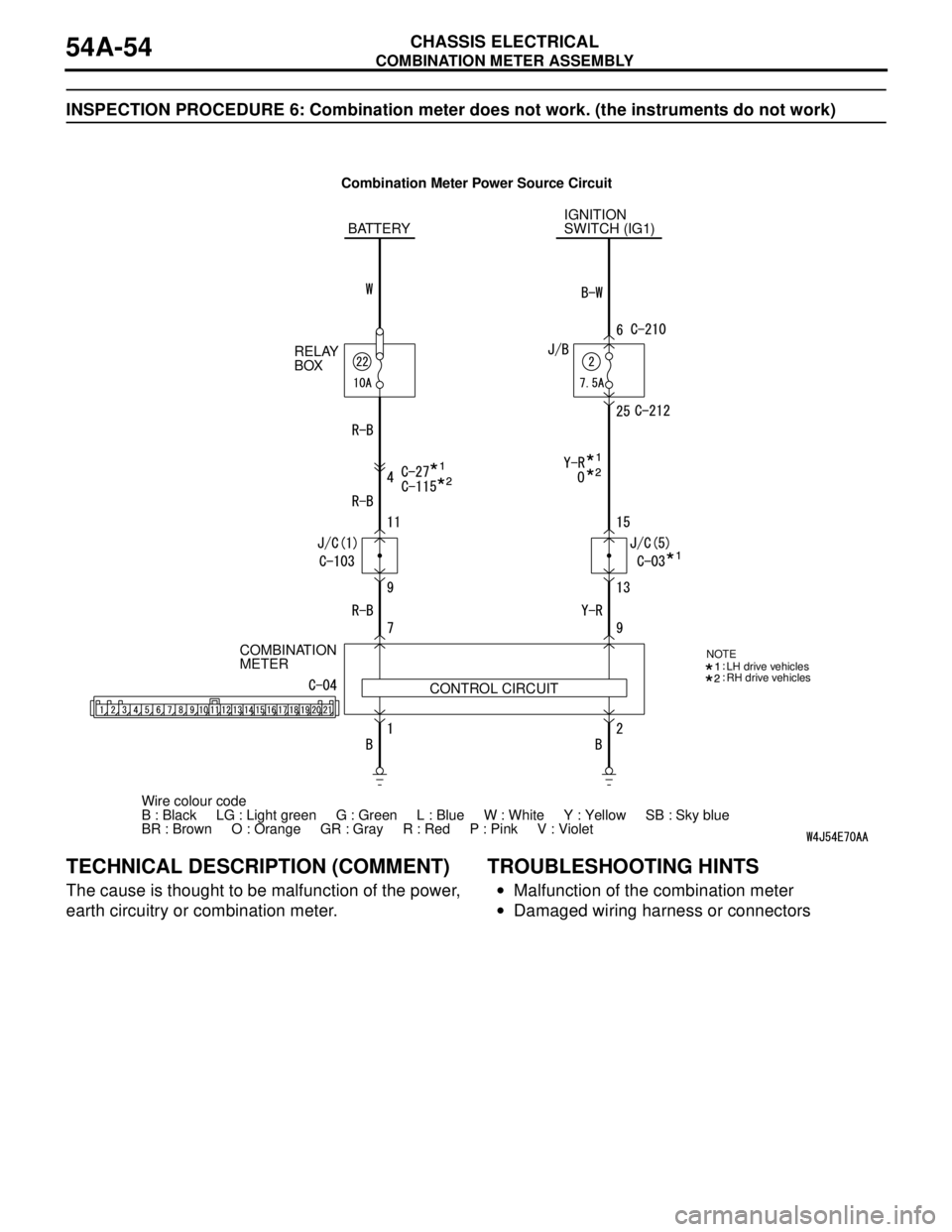
INSPECTION PROCEDURE 6: Combination meter does not work. (the instruments do not work)
TECHNICAL DESCRIPTION (COMMENT)
The cause is thought to be malfunction of the power,
earth circuitry or combination meter.
TROUBLESHOOTING HINTS
•Malfunction of the combination meter
•Damaged wiring harness or connectors
Wire colour code
B : Black LG : Light green G : Green L : Blue W : White Y : Yellow SB : Sky blue
BR : Brown O : Orange GR : Gray R : Red P : Pink V : Violet IGNITION
SWITCH (IG1)
COMBINATION
METER
CONTROL CIRCUIT BATTERY
RELAY
BOX
NOTELH drive vehicles
RH drive vehicles
Combination Meter Power Source Circuit
Page 445 of 788
COMBINATION METER ASSEMBLY
CHASSIS ELECTRICAL54A-57
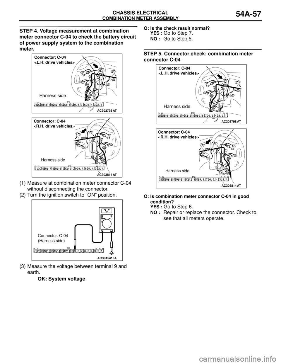
STEP 4. Voltage measurement at combination
meter connector C-04 to check the battery circuit
of power supply system to the combination
meter.
(1) Measure at combination meter connector C-04
without disconnecting the connector.
(2) Turn the ignition switch to “ON” position.
(3) Measure the voltage between terminal 9 and
earth.
OK: System voltageQ: Is the check result normal?
YES :
Go to Step 7.
NO : Go to Step 5.
STEP 5. Connector check: combination meter
connector C-04
Q: Is combination meter connector C-04 in good
condition?
YES :
Go to Step 6.
NO : Repair or replace the connector. Check to
see that all meters operate.
AC303798
Connector: C-04
Harness side
AT
AC303814
Connector: C-04
Harness side
AT
AC301541
Connector: C-04
(Harness side)
FA
AC303798
Connector: C-04
Harness side
AT
AC303814
Connector: C-04
Harness side
AT
Page 446 of 788
COMBINATION METER ASSEMBLY
CHASSIS ELECTRICAL54A-58
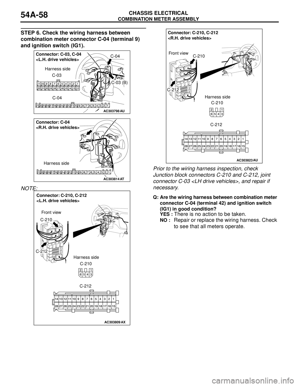
STEP 6. Check the wiring harness between
combination meter connector C-04 (terminal 9)
and ignition switch (IG1).
NOTE: Prior to the wiring harness inspection, check
Junction block connectors C-210 and C-212, joint
connector C-03
necessary.
Q: Are the wiring harness between combination meter
connector C-04 (terminal 42) and ignition switch
(IG1) in good condition?
YES :
There is no action to be taken.
NO : Repair or replace the wiring harness. Check
to see that all meters operate.
AC303798AU
Connector: C-03, C-04
C-03 (B)
C-04 C-03 Harness side
AC303814
Connector: C-04
Harness side
AT
AC303809
Connector: C-210, C-212
C-212
C-210
C-210 Harness side
C-212
AX
Front view
AC303823
Connector: C-210, C-212
C-210
C-212Front view
Harness side
C-210
C-212
AU
Page 483 of 788
REAR WINDOW DEFOGGER
CHASSIS ELECTRICAL54A-95
REAR WINDOW DEFOGGER
GENERAL INFORMATIONM1543000100319
Rear Defogger operation
The defogger relay turns ON if the defogger switch
built-in the A/C-ECU is turned ON when the ignition
switch is in the "ON" position. When the defogger
relay turns ON, power is supplied to the defogger
and the defogger is activated. The defogger comes
with a timer function that causes the defogger switch
to automatically turn OFF in about 11 minutes after
the defogger switch is turned ON.
TROUBLESHOOTINGM1543000701013
The rear window defogger is controlled by the
A/C-ECU. For troubleshooting, refer to GROUP 55-
Troubleshooting P.55-5.
Pre-removal and Post-installation Operation
•Front pillar trim, Centre pillar trim lower, Centre pillar trim
upper, Quarter trim lower, Quarter trim upper (Refer to
GROUP 52A − Trims P.52A-11.)
•Headlining Removal and Installation (Refer to GROUP
52A, Headlining P.52A-21.)
AC305316
AB
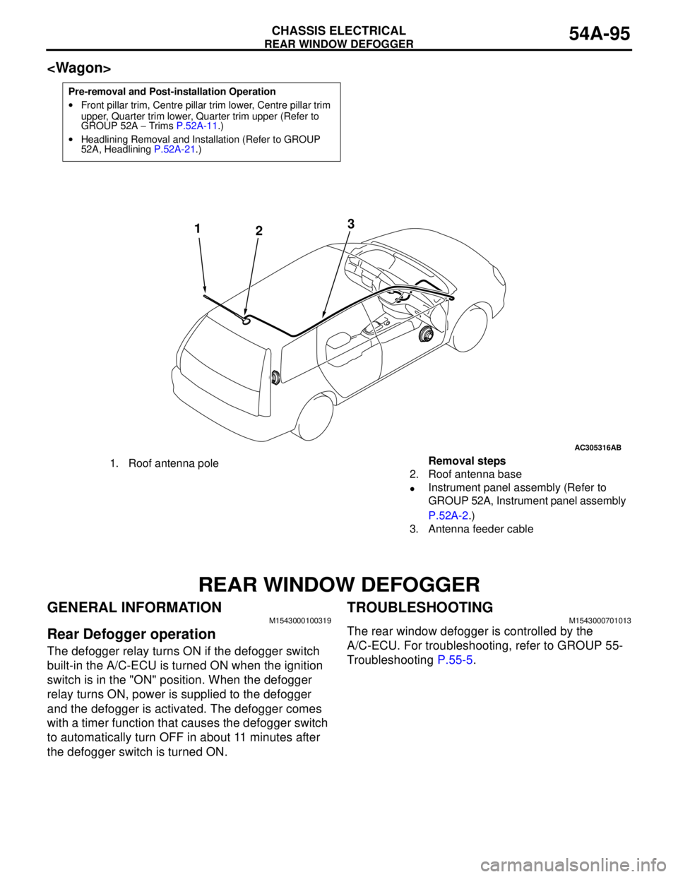
1
23
1. Roof antenna poleRemoval steps
2. Roof antenna base
•Instrument panel assembly (Refer to
GROUP 52A, Instrument panel assembly
P.52A-2.)
3. Antenna feeder cable
Page 616 of 788
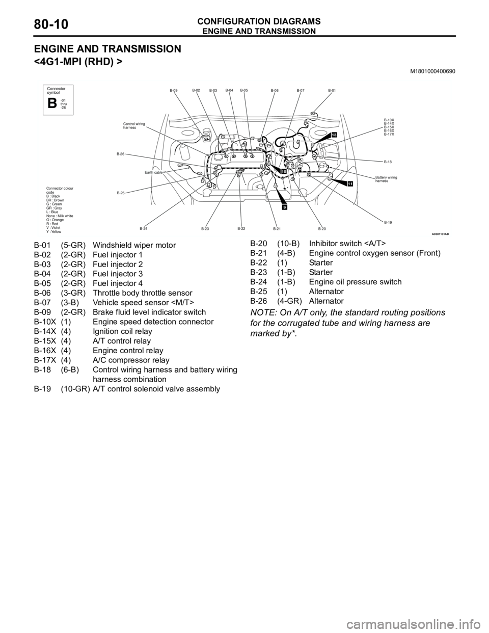
ENGINE AND TRANSMISSION
CONFIGURATION DIAGRAMS80-10
ENGINE AND TRANSMISSION
<4G1-MPI (RHD) >
M1801000400690
NOTE: On A/T only, the standard routing positions
for the corrugated tube and wiring harness are
marked by*.
AC301131
B-02
B-03B-04 B-05
B-22
B-23 B-24 B-25 B-26Control wiring
harnessB-09
Connector colour
code
B : Black
BR : Brown
G : Green
GR : Gray
L : Blue
None : Milk white
O : Orange
R : Red
V : Violet
Y : Yellow*
Connector
symbol
-01
thru
-26B
Earth cable
AB
9
10
11
13
B-06B-07
B-01
B-10X
B-14X
B-15X
B-16X
B-17X
B-18
Battery wiring
harness
B-19
B-20 B-21
*
B-01 (5-GR) Windshield wiper motor
B-02 (2-GR) Fuel injector 1
B-03 (2-GR) Fuel injector 2
B-04 (2-GR) Fuel injector 3
B-05 (2-GR) Fuel injector 4
B-06 (3-GR) Throttle body throttle sensor
B-07 (3-B) Vehicle speed sensor
B-09 (2-GR) Brake fluid level indicator switch
B-10X (1) Engine speed detection connector
B-14X (4) Ignition coil relay
B-15X (4) A/T control relay
B-16X (4) Engine control relay
B-17X (4) A/C compressor relay
B-18 (6-B) Control wiring harness and battery wiring
harness combination
B-19 (10-GR) A/T control solenoid valve assemblyB-20 (10-B) Inhibitor switch
B-21 (4-B) Engine control oxygen sensor (Front)
B-22 (1) Starter
B-23 (1-B) Starter
B-24 (1-B) Engine oil pressure switch
B-25 (1) Alternator
B-26 (4-GR) Alternator
Page 648 of 788
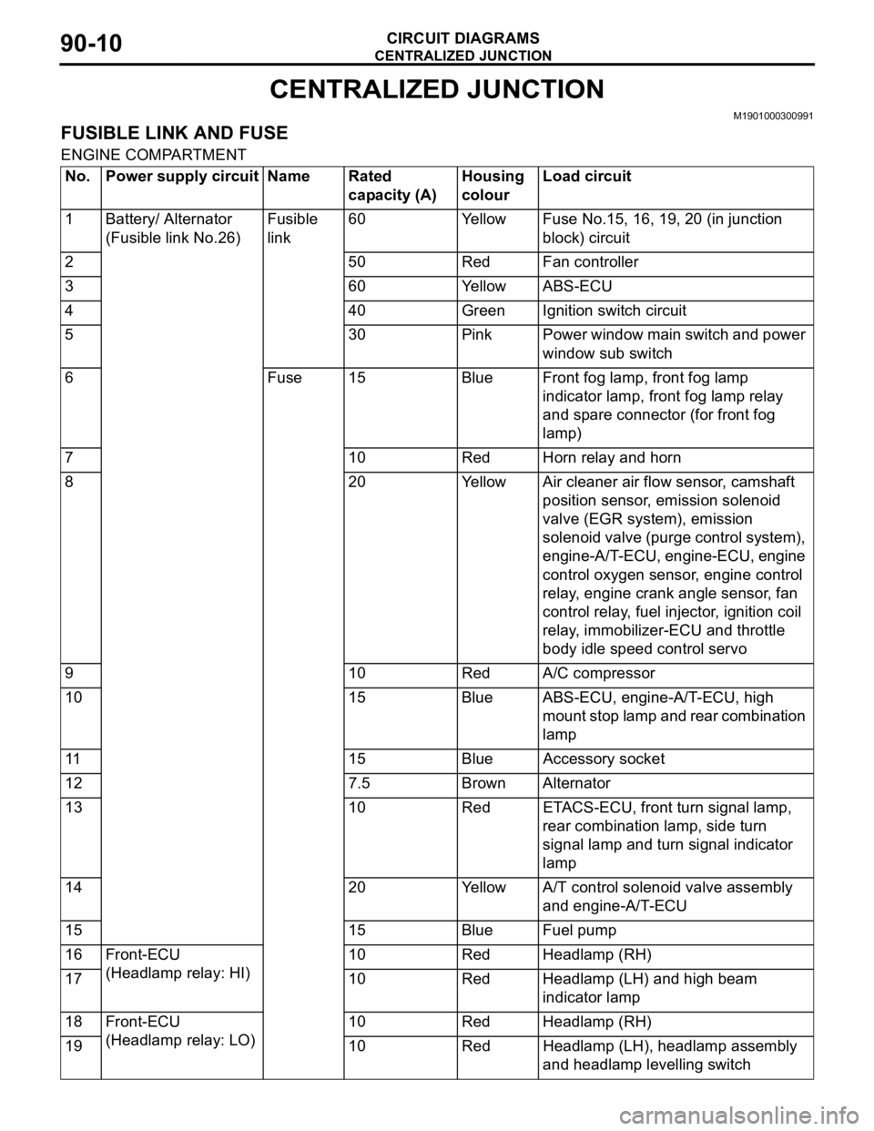
CENTRALIZED JUNCTION
CIRCUIT DIAGRAMS90-10
CENTRALIZED JUNCTION
M1901000300991
FUSIBLE LINK AND FUSE
ENGINE COMPARTMENT
No. Power supply circuit Name Rated
capacity (A)Housing
colourLoad circuit
1 Battery/ Alternator
(Fusible link No.26)Fusible
link60 Yellow Fuse No.15, 16, 19, 20 (in junction
block) circuit
2 50 Red Fan controller
3 60 Yellow ABS-ECU
4 40 Green Ignition switch circuit
5 30 Pink Power window main switch and power
window sub switch
6 Fuse 15 Blue Front fog lamp, front fog lamp
indicator lamp, front fog lamp relay
and spare connector (for front fog
lamp)
7 10 Red Horn relay and horn
8 20 Yellow Air cleaner air flow sensor, camshaft
position sensor, emission solenoid
valve (EGR system), emission
solenoid valve (purge control system),
engine-A/T-ECU, engine-ECU, engine
control oxygen sensor, engine control
relay, engine crank angle sensor, fan
control relay, fuel injector, ignition coil
relay, immobilizer-ECU and throttle
body idle speed control servo
9 10 Red A/C compressor
10 15 Blue ABS-ECU, engine-A/T-ECU, high
mount stop lamp and rear combination
lamp
11 15 Blue Accessory socket
12 7.5 Brown Alternator
13 10 Red ETACS-ECU, front turn signal lamp,
rear combination lamp, side turn
signal lamp and turn signal indicator
lamp
14 20 Yellow A/T control solenoid valve assembly
and engine-A/T-ECU
15 15 Blue Fuel pump
16 Front-ECU
(Headlamp relay: HI)10 Red Headlamp (RH)
17 10 Red Headlamp (LH) and high beam
indicator lamp
18 Front-ECU
(Headlamp relay: LO)10 Red Headlamp (RH)
19 10 Red Headlamp (LH), headlamp assembly
and headlamp levelling switch