direction MITSUBISHI LANCER 2005 Workshop Manual
[x] Cancel search | Manufacturer: MITSUBISHI, Model Year: 2005, Model line: LANCER, Model: MITSUBISHI LANCER 2005Pages: 788, PDF Size: 45.98 MB
Page 10 of 788
ON-VEHICLE SERVICE
ENGINE LUBRICATION12-4
ON-VEHICLE SERVICE
ENGINE OIL CHECKM1121000900342
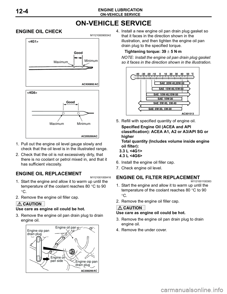
1. Pull out the engine oil level gauge slowly and
check that the oil level is in the illustrated range.
2. Check that the oil is not excessively dirty, that
there is no coolant or petrol mixed in, and that it
has sufficient viscosity.
ENGINE OIL REPLACEMENTM1121001000416
1. Start the engine and allow it to warm up until the
temperature of the coolant reaches 80 °C to 90
°C.
2. Remove the engine oil filler cap.
CAUTION
Use care as engine oil could be hot.
3. Remove the engine oil pan drain plug to drain
engine oil.4. Install a new engine oil pan drain plug gasket so
that it faces in the direction shown in the
illustration, and then tighten the engine oil pan
drain plug to the specified torque.
Tightening torque: 39 ± 5 N⋅m
NOTE: Install the engine oil pan drain plug gasket
so it faces in the direction shown in the illustration.
5. Refill with specified quantity of engine oil.
Specified Engine Oil (ACEA and API
classification): ACEA A1, A2 or A3/API SG or
higher
Total quantity (Includes volume inside engine
oil filter):
3.3 L <4G1>
4.3 L <4G6>
6. Install the engine oil filler cap.
7. Check engine oil level.
ENGINE OIL FILTER REPLACEMENTM1121001100383
1. Start the engine and allow it to warm up until the
temperature of the coolant reaches 80 °C to 90
°C.
2. Remove the engine oil filler cap.
CAUTION
Use care as engine oil could be hot.
3. Remove the engine oil pan drain plug to drain
engine oil.
4. Remove the under cover.
ACX00892 AC
Good
MaximumMinimum
<4G1>
AC205268
Maximum MinimumGood
AC
<4G6>
AC208299
Engine oil pan
AC
Engine oip pan
drain plug
Engine oip pan
drain plug
Engine oil
pan side
AC301513
Page 82 of 788
CHARGING SYSTEM
ENGINE ELECTRICAL16-18
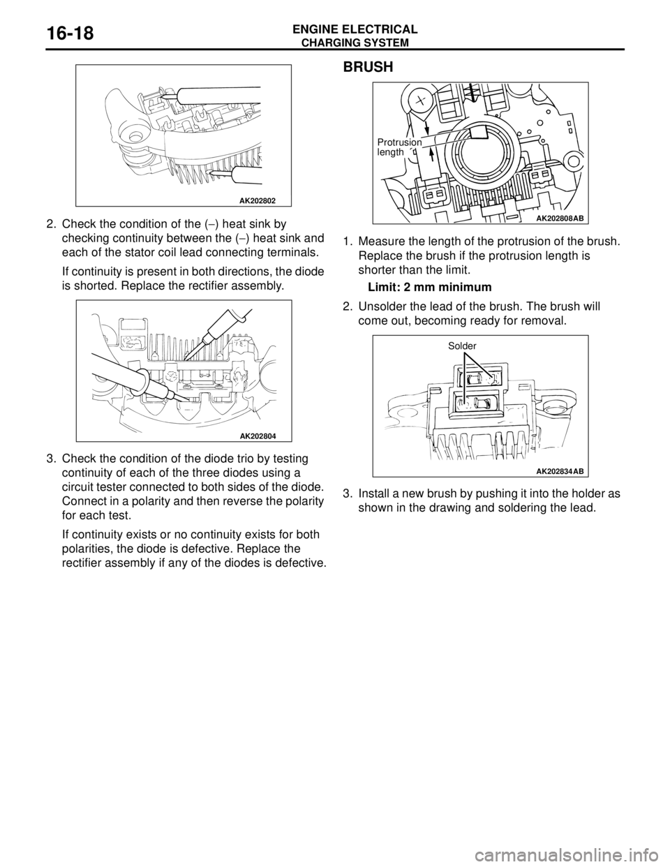
2. Check the condition of the (−) heat sink by
checking continuity between the (−) heat sink and
each of the stator coil lead connecting terminals.
If continuity is present in both directions, the diode
is shorted. Replace the rectifier assembly.
3. Check the condition of the diode trio by testing
continuity of each of the three diodes using a
circuit tester connected to both sides of the diode.
Connect in a polarity and then reverse the polarity
for each test.
If continuity exists or no continuity exists for both
polarities, the diode is defective. Replace the
rectifier assembly if any of the diodes is defective.
BRUSH
1. Measure the length of the protrusion of the brush.
Replace the brush if the protrusion length is
shorter than the limit.
Limit: 2 mm minimum
2. Unsolder the lead of the brush. The brush will
come out, becoming ready for removal.
3. Install a new brush by pushing it into the holder as
shown in the drawing and soldering the lead.
AK202802
AK202804
AK202808
Protrusion
length
AB
AK202834
Solder
AB
Page 96 of 788
IGNITION SYSTEM
ENGINE ELECTRICAL16-32
ON-VEHICLE SERVICE
IGNITION COIL (WITH BUILT-IN POWER
TRANSISTOR) CHECK
M1163001200324
Check by the following procedure, and replace if
there is a malfunction.
SECONDARY COIL RESISTANCE CHECK
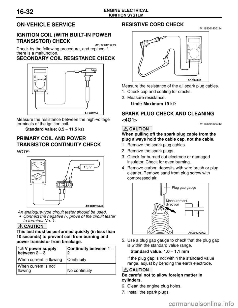
Measure the resistance between the high-voltage
terminals of the ignition coil.
Standard value: 8.5 − 11.5 kΩ
PRIMARY COIL AND POWER
TRANSISTOR CONTINUITY CHECK
NOTE: .•
An analogue-type circuit tester should be used.
•Connect the negative (-) prove of the circuit tester
to terminal No. 1.
CAUTION
This test must be performed quickly (in less than
10 seconds) to prevent coil from burning and
power transistor from breakage.
RESISTIVE CORD CHECKM1163001400124
Measure the resistance of the all spark plug cables.
1. Check cap and coating for cracks.
2. Measure resistance.
Limit: Maximum 19 kΩ
SPARK PLUG CHECK AND CLEANING
<4G1>
M1163004300342
CAUTION
When pulling off the spark plug cable from the
plug always hold the cable cap, not the cable.
1. Remove the spark plug cables.
2. Remove the spark plugs.
3. Check for burned out electrode or damaged
insulator. Check for even burning.
4. Remove carbon deposits with wire brush or plug
cleaner. Remove sand from plug screw with
compressed air.
5. Use a plug gap gauge to check that the plug gap
is within the standard value range.
Standard value: 1.0 − 1.1 mm
If the plug gap is not within the standard value
range, adjust by bending the earth electrode.
CAUTION
Be careful not to allow foreign matter in
cylinders.
6. Clean the engine plug holes.
7. Install the spark plugs. 1.5 V power supply
between 2 − 3Continuity between 1 −
2
When current is flowing Continuity
When current is not
flowing No continuity
AKX01264
AKX01265AD
1.5 V
123 +
–
AKX00382
AKX01272
AG
Plug gap gauge
Measurement
direction
Page 139 of 788
ON-VEHICLE SERVICE
FRONT AXLE26-7
ON-VEHICLE SERVICE
WHEEL BEARING AXIAL PLAY CHECKM1261000900224
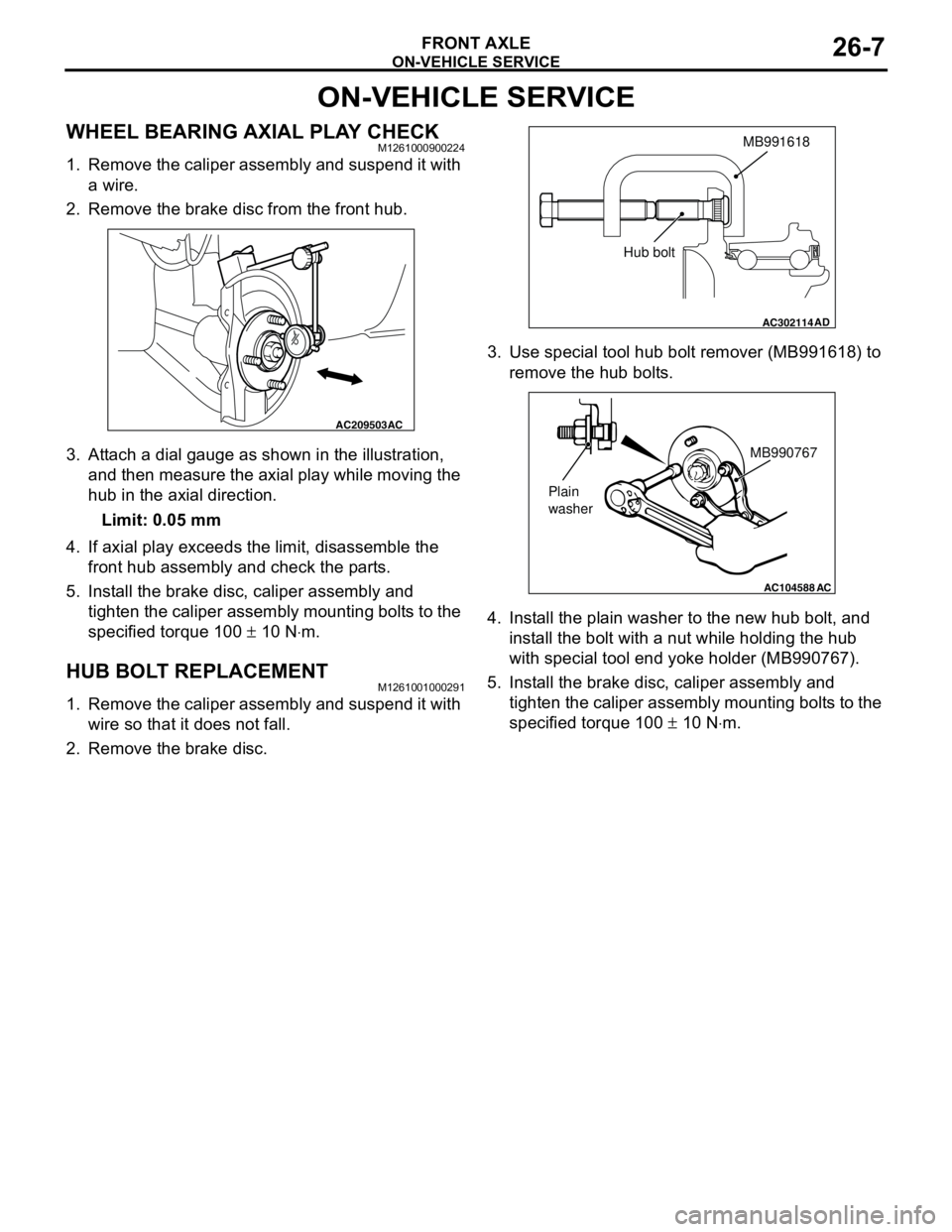
1. Remove the caliper assembly and suspend it with
a wire.
2. Remove the brake disc from the front hub.
3. Attach a dial gauge as shown in the illustration,
and then measure the axial play while moving the
hub in the axial direction.
Limit: 0.05 mm
4. If axial play exceeds the limit, disassemble the
front hub assembly and check the parts.
5. Install the brake disc, caliper assembly and
tighten the caliper assembly mounting bolts to the
specified torque 100 ± 10 N⋅m.
HUB BOLT REPLACEMENTM1261001000291
1. Remove the caliper assembly and suspend it with
wire so that it does not fall.
2. Remove the brake disc.3. Use special tool hub bolt remover (MB991618) to
remove the hub bolts.
4. Install the plain washer to the new hub bolt, and
install the bolt with a nut while holding the hub
with special tool end yoke holder (MB990767).
5. Install the brake disc, caliper assembly and
tighten the caliper assembly mounting bolts to the
specified torque 100 ± 10 N⋅m.
AC209503AC
AC302114
MB991618
AD
Hub bolt
AC104588
MB990767
Plain
washer
AC
Page 142 of 788
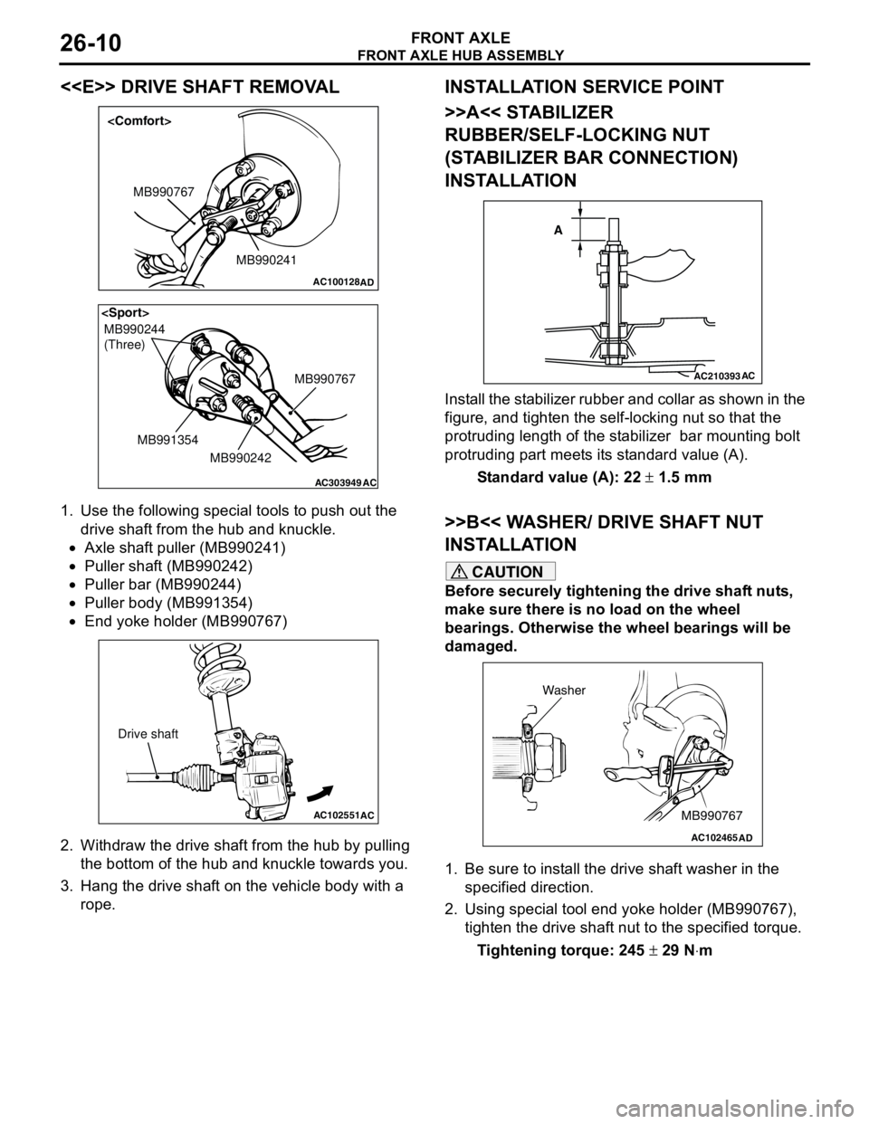
FRONT AXLE HUB ASSEMBLY
FRONT AXLE26-10
<
1. Use the following special tools to push out the
drive shaft from the hub and knuckle.
•Axle shaft puller (MB990241)
•Puller shaft (MB990242)
•Puller bar (MB990244)
•Puller body (MB991354)
•End yoke holder (MB990767)
2. Withdraw the drive shaft from the hub by pulling
the bottom of the hub and knuckle towards you.
3. Hang the drive shaft on the vehicle body with a
rope.
INSTALLATION SERVICE POINT
>>A<< STABILIZER
RUBBER/SELF-LOCKING NUT
(STABILIZER BAR CONNECTION)
INSTALLATION
Install the stabilizer rubber and collar as shown in the
figure, and tighten the self-locking nut so that the
protruding length of the stabilizer bar mounting bolt
protruding part meets its standard value (A).
Standard value (A): 22 ± 1.5 mm
>>B<< WASHER/ DRIVE SHAFT NUT
INSTALLATION
CAUTION
Before securely tightening the drive shaft nuts,
make sure there is no load on the wheel
bearings. Otherwise the wheel bearings will be
damaged.
1. Be sure to install the drive shaft washer in the
specified direction.
2. Using special tool end yoke holder (MB990767),
tighten the drive shaft nut to the specified torque.
Tightening torque: 245 ± 29 N⋅m
AC100128
MB990241 MB990767
AD
AC303949
MB990244
(Three)
MB990767
MB990242 MB991354
AC
AC102551
AC
Drive shaft
AC210393AC
A
AC102465AD
MB990767 Washer
Page 149 of 788
DRIVE SHAFT ASSEMBLY
FRONT AXLE26-17
INSTALLATION SERVICE POINTS
>>A<< DRIVE SHAFT INSTALLATION
CAUTION
When installing the drive shaft, be careful that
the spline part of the drive shaft does not
damage the oil seal.
>>B<< STABILIZER
RUBBER/SELF-LOCKING NUT
(STABILIZER BAR CONNECTION)
INSTALLATION
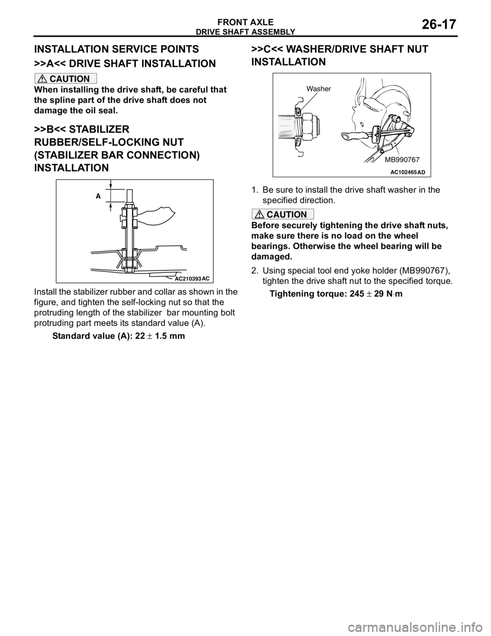
Install the stabilizer rubber and collar as shown in the
figure, and tighten the self-locking nut so that the
protruding length of the stabilizer bar mounting bolt
protruding part meets its standard value (A).
Standard value (A): 22 ± 1.5 mm
>>C<< WASHER/DRIVE SHAFT NUT
INSTALLATION
1. Be sure to install the drive shaft washer in the
specified direction.
CAUTION
Before securely tightening the drive shaft nuts,
make sure there is no load on the wheel
bearings. Otherwise the wheel bearing will be
damaged.
2. Using special tool end yoke holder (MB990767),
tighten the drive shaft nut to the specified torque.
Tightening torque: 245 ± 29 N⋅m
AC210393AC
A
AC102465AD
MB990767 Washer
Page 152 of 788
DRIVE SHAFT ASSEMBLY
FRONT AXLE26-20
REASSEMBLY SERVICE POINTS
>>A<< DYNAMIC DAMPER/DAMPER
BAND/TJ BOOT INSTALLATION
CAUTION
There should be no grease adhered to the rubber
part of the dynamic damper.
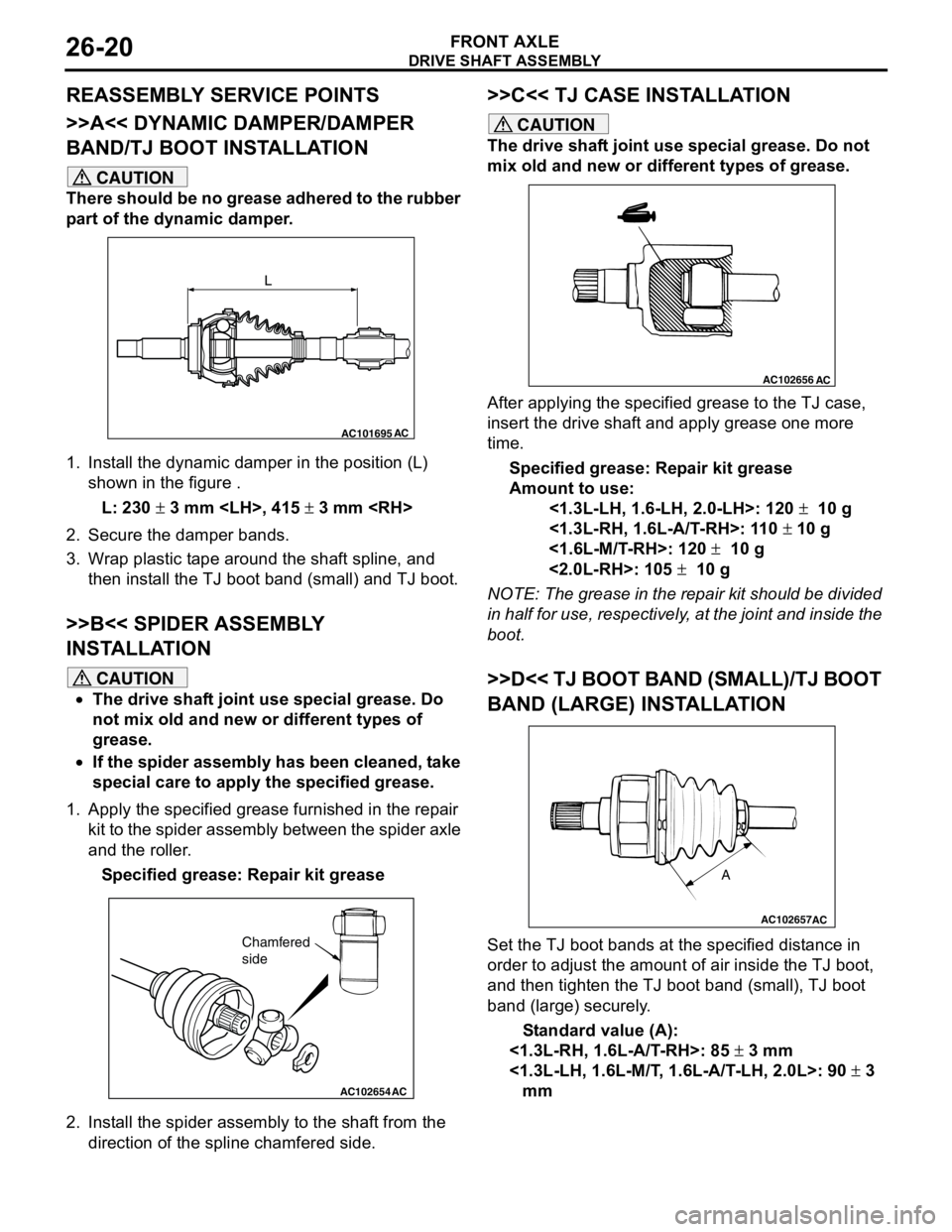
1. Install the dynamic damper in the position (L)
shown in the figure .
L: 230 ± 3 mm
2. Secure the damper bands.
3. Wrap plastic tape around the shaft spline, and
then install the TJ boot band (small) and TJ boot.
>>B<< SPIDER ASSEMBLY
INSTALLATION
CAUTION
•The drive shaft joint use special grease. Do
not mix old and new or different types of
grease.
•If the spider assembly has been cleaned, take
special care to apply the specified grease.
1. Apply the specified grease furnished in the repair
kit to the spider assembly between the spider axle
and the roller.
Specified grease: Repair kit grease
2. Install the spider assembly to the shaft from the
direction of the spline chamfered side.
>>C<< TJ CASE INSTALLATION
CAUTION
The drive shaft joint use special grease. Do not
mix old and new or different types of grease.
After applying the specified grease to the TJ case,
insert the drive shaft and apply grease one more
time.
Specified grease: Repair kit grease
Amount to use:
<1.3L-LH, 1.6-LH, 2.0-LH>: 120 ± 10 g
<1.3L-RH, 1.6L-A/T-RH>: 110 ± 10 g
<1.6L-M/T-RH>: 120 ± 10 g
<2.0L-RH>: 105 ± 10 g
NOTE: The grease in the repair kit should be divided
in half for use, respectively, at the joint and inside the
boot.
>>D<< TJ BOOT BAND (SMALL)/TJ BOOT
BAND (LARGE) INSTALLATION
Set the TJ boot bands at the specified distance in
order to adjust the amount of air inside the TJ boot,
and then tighten the TJ boot band (small), TJ boot
band (large) securely.
Standard value (A):
<1.3L-RH, 1.6L-A/T-RH>: 85 ± 3 mm
<1.3L-LH, 1.6L-M/T, 1.6L-A/T-LH, 2.0L>: 90 ± 3
mm
AC101695AC
L
AC102654AC
Chamfered
side
AC102656AC
AC102657
A
AC
Page 160 of 788
ON-VEHICLE SERVICE
REAR AXLE27-4
ON-VEHICLE SERVICE
WHEEL BEARING AXIAL PLAY CHECKM1271000900452
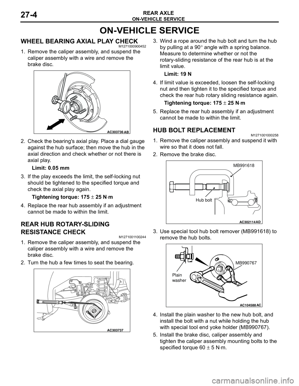
1. Remove the caliper assembly, and suspend the
caliper assembly with a wire and remove the
brake disc.
2. Check the bearing's axial play. Place a dial gauge
against the hub surface; then move the hub in the
axial direction and check whether or not there is
axial play.
Limit: 0.05 mm
3. If the play exceeds the limit, the self-locking nut
should be tightened to the specified torque and
check the axial play again.
Tightening torque: 175 ± 25 N⋅m
4. Replace the rear hub assembly if an adjustment
cannot be made to within the limit.
REAR HUB ROTARY-SLIDING
RESISTANCE CHECK
M1271001100244
1. Remove the caliper assembly, and suspend the
caliper assembly with a wire and remove the
brake disc.
2. Turn the hub a few times to seat the bearing.3. Wind a rope around the hub bolt and turn the hub
by pulling at a 90° angle with a spring balance.
Measure to determine whether or not the
rotary-sliding resistance of the rear hub is at the
limit value.
Limit: 19 N
4. If limit value is exceeded, loosen the self-locking
nut and then tighten it to the specified torque and
check the rear hub rotary sliding resistance again.
Tightening torque: 175 ± 25 N⋅m
5. Replace the rear hub assembly if an adjustment
cannot be made to within the limit.
HUB BOLT REPLACEMENTM1271001000258
1. Remove the caliper assembly and suspend it with
wire so that it does not fall.
2. Remove the brake disc.
3. Use special tool hub bolt remover (MB991618) to
remove the hub bolts.
4. Install the plain washer to the new hub bolt, and
install the bolt with a nut while holding the hub
with special tool end yoke holder (MB990767).
5. Install the brake disc, caliper assembly and
tighten the caliper assembly mounting bolts to the
specified torque 60 ± 5 N⋅m.
AC303736AB
AC303737
AC302114
MB991618
AD
Hub bolt
AC104588
MB990767
Plain
washer
AC
Page 187 of 788
ON-VEHICLE SERVICE
FRONT SUSPENSION33-5
ON-VEHICLE SERVICE
FRONT WHEEL ALIGNMENT CHECK AND
ADJUSTMENT
M1331000900682
Measure wheel alignment with alignment equipment
on a level surface. The front suspension, steering
system, wheels, and tyres should be serviced to
normal condition before measuring wheel alignment.
TOE-IN
Standard value:
at the centre of tyre tread: 1 ± 2 mm
Toe angle (per wheel): 0°03' ± 06'
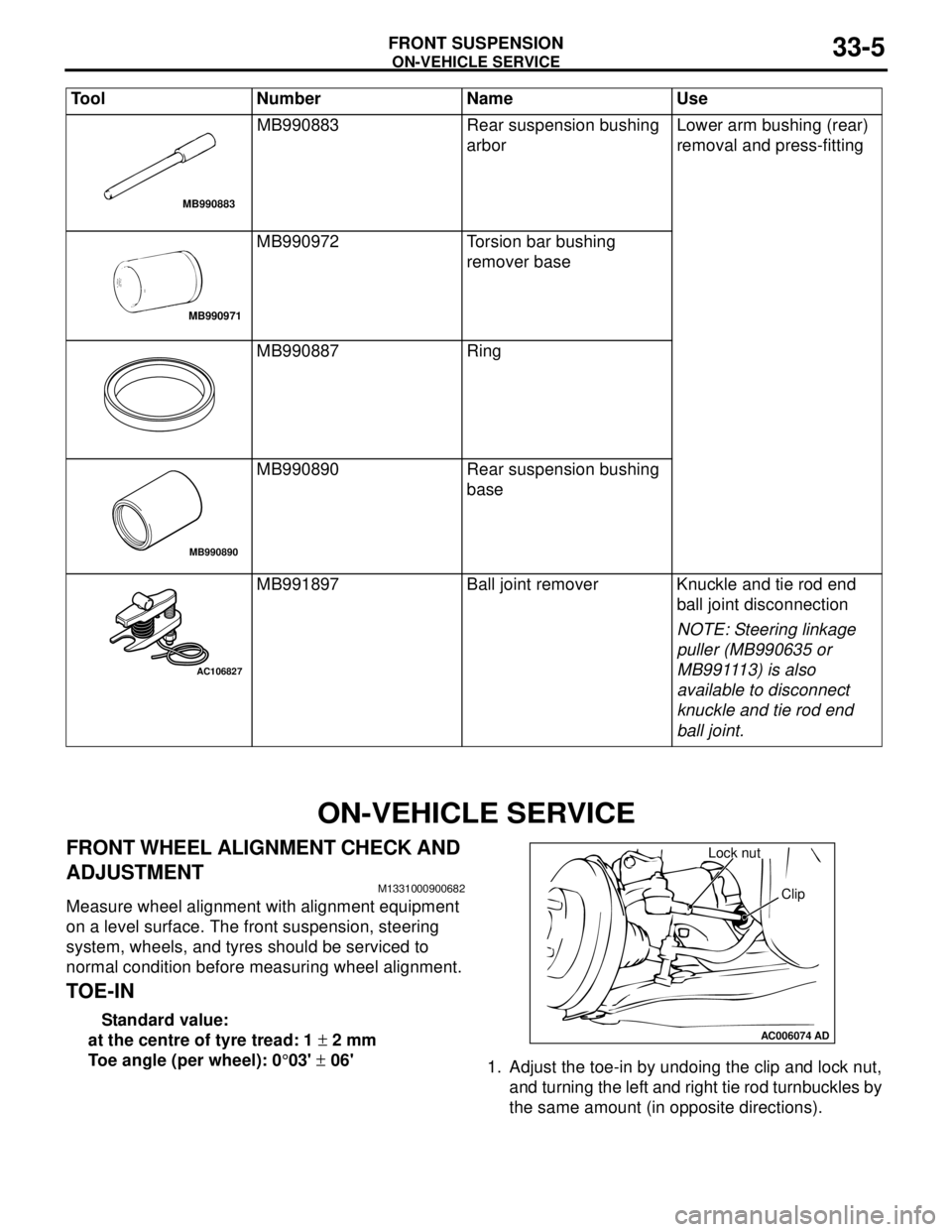
1. Adjust the toe-in by undoing the clip and lock nut,
and turning the left and right tie rod turnbuckles by
the same amount (in opposite directions). MB990883 Rear suspension bushing
arborLower arm bushing (rear)
removal and press-fitting
MB990972 Torsion bar bushing
remover base
MB990887 Ring
MB990890 Rear suspension bushing
base
MB991897 Ball joint remover Knuckle and tie rod end
ball joint disconnection
NOTE: Steering linkage
puller (MB990635 or
MB991113) is also
available to disconnect
knuckle and tie rod end
ball joint. Tool Number Name Use
MB990883
MB990971
MB990890
AC106827
AC006074AD
Lock nut
Clip
Page 188 of 788
ON-VEHICLE SERVICE
FRONT SUSPENSION33-6
NOTE: The toe will move out as the left
turnbuckle is turned toward the front of the vehicle
and the right turnbuckle is turned toward the rear
of the vehicle.
2. Install the clip and tighten the lock nut to the
specified torque.
Tightening torque: 40 ± 5 N⋅m
3. Confirm that the toe-in is at the standard value.
4. Use a turning radius gauge to check that the
steering angle is at the standard value.
STEERING ANGLE
Standard value:
TOE-OUT ANGLE ON TURNS
To check the steering linkage, especially after the
vehicle has been involved in an accident or if an
accident is presumed, it is advisable to check the
toe-out angle on turns in addition to the wheel
alignment.
Conduct this test on the left turn as well as on the
right turn.
Standard value:
CAMBER, CASTER AND KINGPIN
INCLINATION
Standard value:NOTE: *: difference between right and left wheels
must be less than 30'
NOTE: Camber and caster are preset at the factory
and cannot be adjusted.
CAUTION
Never subject the wheel bearings to the vehicle
load when the driveshaft nuts are loosened.
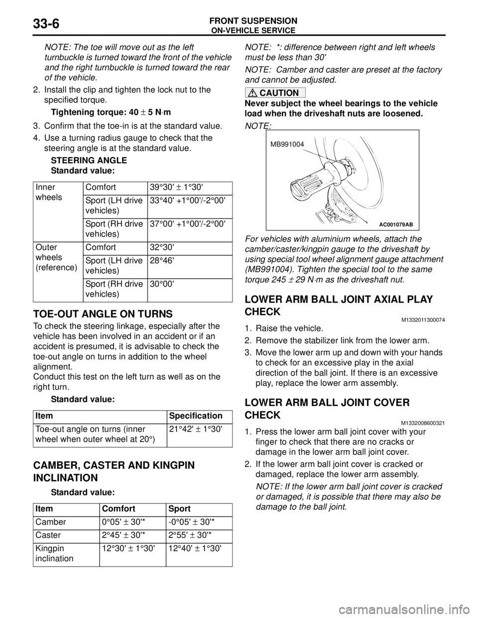
NOTE:
For vehicles with aluminium wheels, attach the
camber/caster/kingpin gauge to the driveshaft by
using special tool wheel alignment gauge attachment
(MB991004). Tighten the special tool to the same
torque 245
± 29 N⋅m as the driveshaft nut.
LOWER ARM BALL JOINT AXIAL PLAY
CHECK
M1332011300074
1. Raise the vehicle.
2. Remove the stabilizer link from the lower arm.
3. Move the lower arm up and down with your hands
to check for an excessive play in the axial
direction of the ball joint. If there is an excessive
play, replace the lower arm assembly.
LOWER ARM BALL JOINT COVER
CHECK
M1332008600321
1. Press the lower arm ball joint cover with your
finger to check that there are no cracks or
damage in the lower arm ball joint cover.
2. If the lower arm ball joint cover is cracked or
damaged, replace the lower arm assembly.
NOTE: If the lower arm ball joint cover is cracked
or damaged, it is possible that there may also be
damage to the ball joint. Inner
wheelsComfort 39°30' ± 1°30'
Sport (LH drive
vehicles)33°40' +1°00'/-2°00'
Sport (RH drive
vehicles)37°00' +1°00'/-2°00'
Outer
wheels
(reference)Comfort 32°30'
Sport (LH drive
vehicles)28°46'
Sport (RH drive
vehicles)30°00'
Item Specification
Toe-out angle on turns (inner
wheel when outer wheel at 20°)21°42' ± 1°30'
Item Comfort Sport
Camber 0°05' ± 30'* -0°05' ± 30'*
Caster 2°45' ± 30'* 2°55' ± 30'*
Kingpin
inclination12°30' ± 1°30' 12°40' ± 1°30'
AC001079
MB991004
AB