oil filter MITSUBISHI LANCER 2005 Workshop Manual
[x] Cancel search | Manufacturer: MITSUBISHI, Model Year: 2005, Model line: LANCER, Model: MITSUBISHI LANCER 2005Pages: 788, PDF Size: 45.98 MB
Page 7 of 788
12-1
GROUP 12
ENGINE
LUBRICATION
CONTENTS
GENERAL INFORMATION . . . . . . . .12-2
SERVICE SPECIFICATION . . . . . . . .12-2
LUBRICANT . . . . . . . . . . . . . . . . . . . .12-2
SEALANT . . . . . . . . . . . . . . . . . . . . . .12-3SPECIAL TOOLS . . . . . . . . . . . . . . . .12-3
ON-VEHICLE SERVICE . . . . . . . . . . .12-4
ENGINE OIL CHECK . . . . . . . . . . . . . . . . . 12-4
ENGINE OIL REPLACEMENT . . . . . . . . . . 12-4
ENGINE OIL FILTER REPLACEMENT . . . . 12-4
OIL PRESSURE CHECK . . . . . . . . . . . . . . 12-5
Page 8 of 788

GENERAL INFORMATION
ENGINE LUBRICATION12-2
GENERAL INFORMATION
M1121000100357
The lubrication method is a fully force-fed, full-flow
filtration type. The engine oil pump is a trochoid type
which is driven by the crankshaft <4G1>.The engine
oil pump is a gear type which is driven by the
crankshaft via the balancer timing belt <4G6>.
ENGINE OILS
Health Warning
Prolonged and repeated contact with mineral oil will
result in the removal of natural fats from the skin,
leading to dryness, irritation and dermatitis. In
addition, used engine oil contains potentially harmful
contaminants which may cause skin cancer.
Adequate means of skin protection and washing
facilities must be provided.
Recommended Precautions
The most effective precaution is to adapt working
practices which prevent, as far as practicable, the
risk of skin contact with mineral oils, for example by
using enclosed systems for handling used engine oil
and by degreasing components, where practicable,
before handling them. Other precautions:
•Avoid prolonged and repeated contact with oils,
particularly used engine oils.
•Wear protective clothing, including impervious
gloves where practicable.•Avoid contaminating clothes, particularly
underpants, with oil.
•Do not put oily rags in pockets, the use of overalls
without pockets will avoid this.
•Do not wear heavily soiled clothing and
oil-impregnated foot-wear. Overalls must be
cleaned regularly and kept separate from
personal clothing.
•Where there is a risk of eye contact, eye
protection should be worn, for example, chemical
goggles or face shields; in addition an eye wash
facility should be provided.
•Obtain first aid treatment immediately for open
cuts and wounds.
•Wash regularly with soap and water to ensure all
oil is removed, especially before meals (skin
cleansers and nail brushes will help). After
cleaning, the application of preparations
containing lanolin to replace the natural skin oils
is advised.
•Do not use petrol, kerosine, diesel fuel, gas oil,
thinners or solvents for cleaning skin.
•Use barrier creams, applying them before each
work period, to help the removal of oil from the
skin after work.
•If skin disorders develop, obtain medical advice
without delay.
SERVICE SPECIFICATION
M1121000300232
LUBRICANT
M1121000400433
Item Standard value
Oil pressure kPa at idle 29 or more
at 3,500 r/min 294 − 686
Item Specification
Engine oil ACEA classification A1, A2 or A3
Engine oil API classification SG or higher
Engine oil quantity L 4G1 Oil filter 0.3
To t a l 3 . 3
4G6 Oil filter 0.3
To t a l 4 . 3
Page 9 of 788
SEALANT
ENGINE LUBRICATION12-3
SEALANT
M1121000500258
SPECIAL TOOLS
M1121000600415
Item Specified sealant Remark
Oil pressure switch 3M ATD Part No. 8660 or equivalent Semi-drying sealant
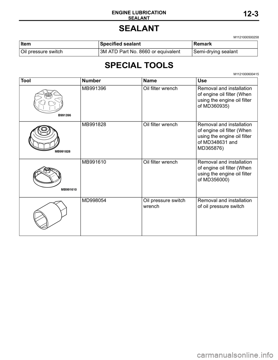
Tool Number Name Use
MB991396 Oil filter wrench Removal and installation
of engine oil filter (When
using the engine oil filter
of MD360935)
MB991828 Oil filter wrench Removal and installation
of engine oil filter (When
using the engine oil filter
of MD348631 and
MD365876)
MB991610 Oil filter wrench Removal and installation
of engine oil filter (When
using the engine oil filter
of MD356000)
MD998054 Oil pressure switch
wrenchRemoval and installation
of oil pressure switch
B991396
MB991828
MB991610
Page 10 of 788
ON-VEHICLE SERVICE
ENGINE LUBRICATION12-4
ON-VEHICLE SERVICE
ENGINE OIL CHECKM1121000900342
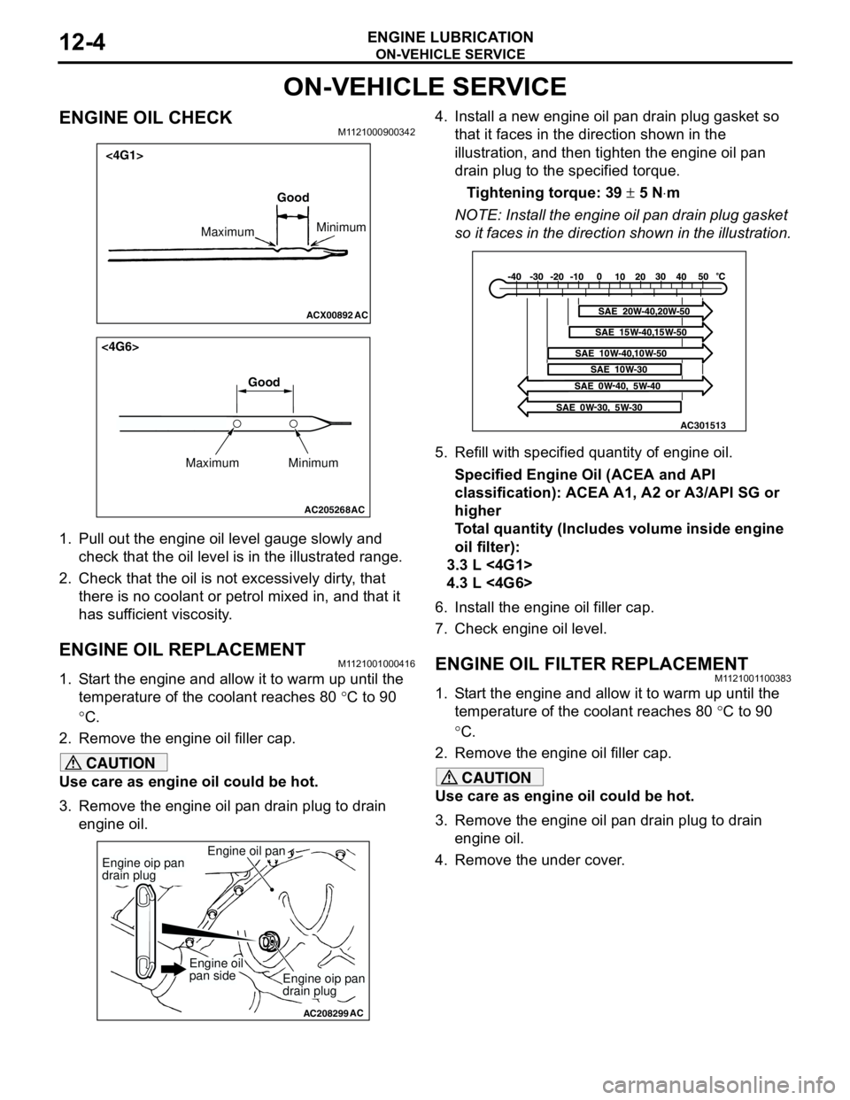
1. Pull out the engine oil level gauge slowly and
check that the oil level is in the illustrated range.
2. Check that the oil is not excessively dirty, that
there is no coolant or petrol mixed in, and that it
has sufficient viscosity.
ENGINE OIL REPLACEMENTM1121001000416
1. Start the engine and allow it to warm up until the
temperature of the coolant reaches 80 °C to 90
°C.
2. Remove the engine oil filler cap.
CAUTION
Use care as engine oil could be hot.
3. Remove the engine oil pan drain plug to drain
engine oil.4. Install a new engine oil pan drain plug gasket so
that it faces in the direction shown in the
illustration, and then tighten the engine oil pan
drain plug to the specified torque.
Tightening torque: 39 ± 5 N⋅m
NOTE: Install the engine oil pan drain plug gasket
so it faces in the direction shown in the illustration.
5. Refill with specified quantity of engine oil.
Specified Engine Oil (ACEA and API
classification): ACEA A1, A2 or A3/API SG or
higher
Total quantity (Includes volume inside engine
oil filter):
3.3 L <4G1>
4.3 L <4G6>
6. Install the engine oil filler cap.
7. Check engine oil level.
ENGINE OIL FILTER REPLACEMENTM1121001100383
1. Start the engine and allow it to warm up until the
temperature of the coolant reaches 80 °C to 90
°C.
2. Remove the engine oil filler cap.
CAUTION
Use care as engine oil could be hot.
3. Remove the engine oil pan drain plug to drain
engine oil.
4. Remove the under cover.
ACX00892 AC
Good
MaximumMinimum
<4G1>
AC205268
Maximum MinimumGood
AC
<4G6>
AC208299
Engine oil pan
AC
Engine oip pan
drain plug
Engine oip pan
drain plug
Engine oil
pan side
AC301513
Page 11 of 788
ON-VEHICLE SERVICE
ENGINE LUBRICATION12-5
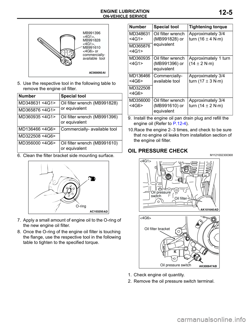
5. Use the respective tool in the following table to
remove the engine oil filter.
6. Clean the filter bracket side mounting surface.
7. Apply a small amount of engine oil to the O-ring of
the new engine oil filter.
8. Once the O-ring of the engine oil filter is touching
the flange, use the respective tool in the following
table to tighten to the specified torque.9. Install the engine oil pan drain plug and refill the
engine oil (Refer to P.12-4).
10.Race the engine 2−3 times, and check to be sure
that no engine oil leaks from installation section of
the engine oil filter.
OIL PRESSURE CHECKM1121002300368
1. Check engine oil quantity.
2. Remove the oil pressure switch terminal. Number Special tool
MD348631 <4G1> Oil filter wrench (MB991828)
or equivalent
MD365876 <4G1>
MD360935 <4G1> Oil filter wrench (MB991396)
or equivalent
MD136466 <4G6> Commercially- available tool
MD322508 <4G6>
MD356000 <4G6> Oil filter wrench (MB991610)
or equivalent
AC000093
MB991396
<4G1>,
MB991828
<4G1>,
MB991610
<4G6> or
commercially-
available tool
AI
AC103250AD
O-ring
Number Special tool Tightening torque
MD348631
<4G1>Oil filter wrench
(MB991828) or
equivalentApproximately 3/4
turn (16 ± 4 N⋅m)
MD365876
<4G1>
MD360935
<4G1>Oil filter wrench
(MB991396) or
equivalentApproximately 1 turn
(14 ± 2 N⋅m)
MD136466
<4G6>Commercially-
available toolApproximately 3/4
turn (17 ± 3 N⋅m)
MD322508
<4G6>
MD356000
<4G6>Oil filter wrench
(MB991610) or
equivalentApproximately 3/4
turn (14 ± 2 N⋅m)
AK101640
<4G1>
Oil pressure
switch
Oil filter
AD
AK300647
AB
<4G6>
Oil filter bracket
Oil pressure switch
Page 486 of 788
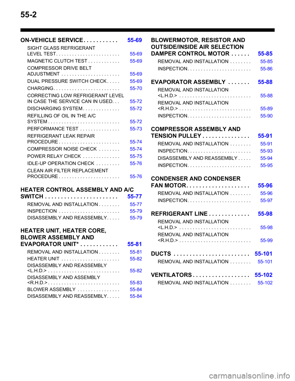
55-2
ON-VEHICLE SERVICE . . . . . . . . . . .55-69
SIGHT GLASS REFRIGERANT
LEVEL TEST . . . . . . . . . . . . . . . . . . . . . . . . 55-69
MAGNETIC CLUTCH TEST . . . . . . . . . . . . 55-69
COMPRESSOR DRIVE BELT
ADJUSTMENT . . . . . . . . . . . . . . . . . . . . . . 55-69
DUAL PRESSURE SWITCH CHECK . . . . . 55-69
CHARGING . . . . . . . . . . . . . . . . . . . . . . . . . 55-70
CORRECTING LOW REFRIGERANT LEVEL
IN CASE THE SERVICE CAN IN USED. . . 55-72
DISCHARGING SYSTEM . . . . . . . . . . . . . . 55-72
REFILLING OF OIL IN THE A/C
SYSTEM . . . . . . . . . . . . . . . . . . . . . . . . . . . 55-72
PERFORMANCE TEST . . . . . . . . . . . . . . . 55-73
REFRIGERANT LEAK REPAIR
PROCEDURE . . . . . . . . . . . . . . . . . . . . . . . 55-74
COMPRESSOR NOISE CHECK . . . . . . . . 55-74
POWER RELAY CHECK . . . . . . . . . . . . . . 55-75
IDLE-UP OPERATION CHECK . . . . . . . . . 55-76
CLEAN AIR FILTER REPLACEMENT
PROCEDURE . . . . . . . . . . . . . . . . . . . . . . . 55-76
HEATER CONTROL ASSEMBLY AND A/C
SWITCH . . . . . . . . . . . . . . . . . . . . . . .55-77
REMOVAL AND INSTALLATION . . . . . . . . 55-77
INSPECTION . . . . . . . . . . . . . . . . . . . . . . . 55-79
DISASSEMBLY AND REASSEMBLY . . . . . 55-79
HEATER UNIT, HEATER CORE,
BLOWER ASSEMBLY AND
EVAPORATOR UNIT* . . . . . . . . . . . .55-81
REMOVAL AND INSTALLATION . . . . . . . . 55-81
HEATER UNIT . . . . . . . . . . . . . . . . . . . . . . 55-82
DISASSEMBLY AND REASSEMBLY
DISASSEMBLY AND ASSEMBLY
BLOWER ASSEMBLY . . . . . . . . . . . . . . . . 55-84
DISASSEMBLY AND REASSEMBLY . . . . . 55-84
BLOWERMOTOR, RESISTOR AND
OUTSIDE/INSIDE AIR SELECTION
DAMPER CONTROL MOTOR . . . . . .55-85
REMOVAL AND INSTALLATION . . . . . . . . 55-85
INSPECTION . . . . . . . . . . . . . . . . . . . . . . . . 55-86
EVAPORATOR ASSEMBLY . . . . . . .55-88
REMOVAL AND INSTALLATION
REMOVAL AND INSTALLATION
INSPECTION . . . . . . . . . . . . . . . . . . . . . . . . 55-90
COMPRESSOR ASSEMBLY AND
TENSION PULLEY . . . . . . . . . . . . . . .55-91
REMOVAL AND INSTALLATION . . . . . . . . 55-91
INSPECTION . . . . . . . . . . . . . . . . . . . . . . . . 55-93
DISASSEMBLY AND REASSEMBLY . . . . . 55-94
INSPECTION . . . . . . . . . . . . . . . . . . . . . . . . 55-95
CONDENSER AND CONDENSER
FAN MOTOR . . . . . . . . . . . . . . . . . . . .55-96
REMOVAL AND INSTALLATION . . . . . . . . 55-96
INSPECTION . . . . . . . . . . . . . . . . . . . . . . . . 55-97
REFRIGERANT LINE . . . . . . . . . . . . .55-98
REMOVAL AND INSTALLATION
REMOVAL AND INSTALLATION
DUCTS . . . . . . . . . . . . . . . . . . . . . . . .55-101
REMOVAL AND INSTALLATION . . . . . . . . 55-101
VENTILATORS . . . . . . . . . . . . . . . . . .55-102
REMOVAL AND INSTALLATION . . . . . . . . 55-102
Page 558 of 788
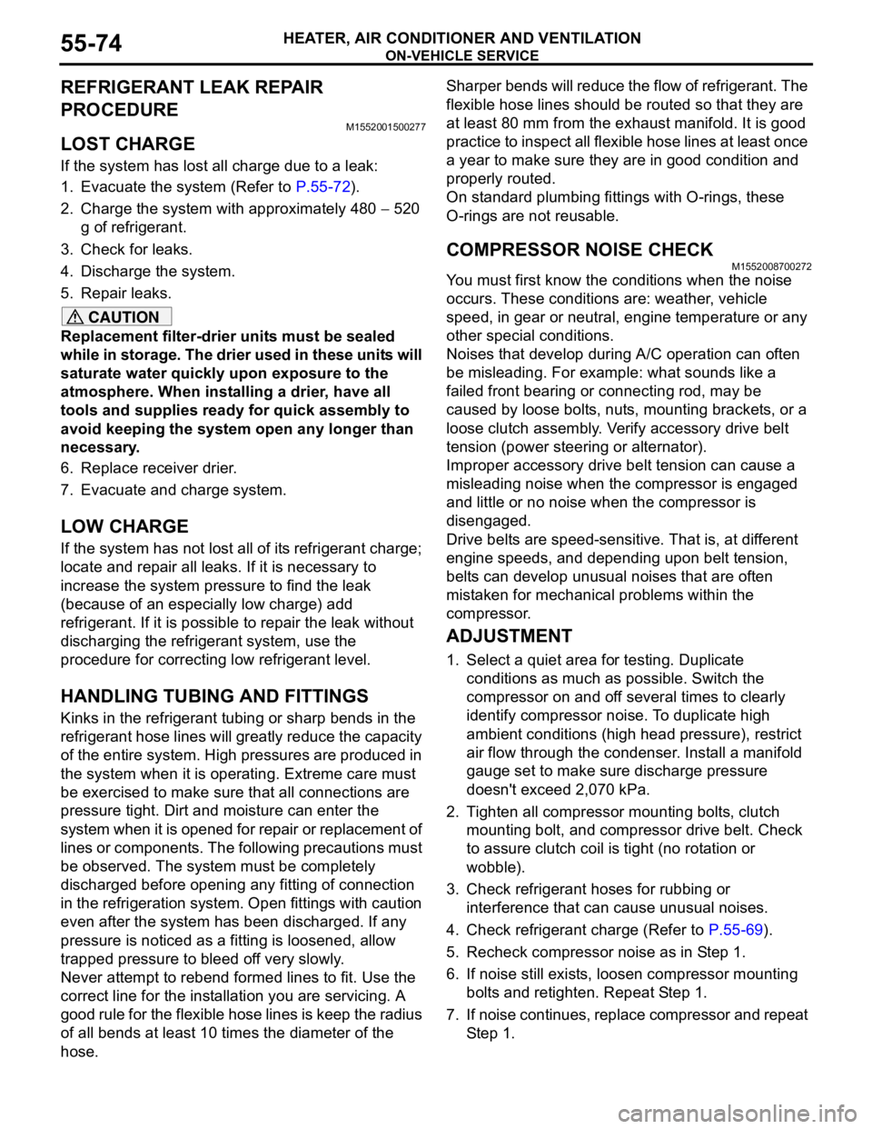
ON-VEHICLE SERVICE
HEATER, AIR CONDITIONER AND VENTILATION55-74
REFRIGERANT LEAK REPAIR
PROCEDURE
M1552001500277
LOST CHARGE
If the system has lost all charge due to a leak:
1. Evacuate the system (Refer to P.55-72).
2. Charge the system with approximately 480 − 520
g of refrigerant.
3. Check for leaks.
4. Discharge the system.
5. Repair leaks.
CAUTION
Replacement filter-drier units must be sealed
while in storage. The drier used in these units will
saturate water quickly upon exposure to the
atmosphere. When installing a drier, have all
tools and supplies ready for quick assembly to
avoid keeping the system open any longer than
necessary.
6. Replace receiver drier.
7. Evacuate and charge system.
LOW CHARGE
If the system has not lost all of its refrigerant charge;
locate and repair all leaks. If it is necessary to
increase the system pressure to find the leak
(because of an especially low charge) add
refrigerant. If it is possible to repair the leak without
discharging the refrigerant system, use the
procedure for correcting low refrigerant level.
HANDLING TUBING AND FITTINGS
Kinks in the refrigerant tubing or sharp bends in the
refrigerant hose lines will greatly reduce the capacity
of the entire system. High pressures are produced in
the system when it is operating. Extreme care must
be exercised to make sure that all connections are
pressure tight. Dirt and moisture can enter the
system when it is opened for repair or replacement of
lines or components. The following precautions must
be observed. The system must be completely
discharged before opening any fitting of connection
in the refrigeration system. Open fittings with caution
even after the system has been discharged. If any
pressure is noticed as a fitting is loosened, allow
trapped pressure to bleed off very slowly.
Never attempt to rebend formed lines to fit. Use the
correct line for the installation you are servicing. A
good rule for the flexible hose lines is keep the radius
of all bends at least 10 times the diameter of the
hose.Sharper bends will reduce the flow of refrigerant. The
flexible hose lines should be routed so that they are
at least 80 mm from the exhaust manifold. It is good
practice to inspect all flexible hose lines at least once
a year to make sure they are in good condition and
properly routed.
On standard plumbing fittings with O-rings, these
O-rings are not reusable.
COMPRESSOR NOISE CHECKM1552008700272
You must first know the conditions when the noise
occurs. These conditions are: weather, vehicle
speed, in gear or neutral, engine temperature or any
other special conditions.
Noises that develop during A/C operation can often
be misleading. For example: what sounds like a
failed front bearing or connecting rod, may be
caused by loose bolts, nuts, mounting brackets, or a
loose clutch assembly. Verify accessory drive belt
tension (power steering or alternator).
Improper accessory drive belt tension can cause a
misleading noise when the compressor is engaged
and little or no noise when the compressor is
disengaged.
Drive belts are speed-sensitive. That is, at different
engine speeds, and depending upon belt tension,
belts can develop unusual noises that are often
mistaken for mechanical problems within the
compressor.
ADJUSTMENT
1. Select a quiet area for testing. Duplicate
conditions as much as possible. Switch the
compressor on and off several times to clearly
identify compressor noise. To duplicate high
ambient conditions (high head pressure), restrict
air flow through the condenser. Install a manifold
gauge set to make sure discharge pressure
doesn't exceed 2,070 kPa.
2. Tighten all compressor mounting bolts, clutch
mounting bolt, and compressor drive belt. Check
to assure clutch coil is tight (no rotation or
wobble).
3. Check refrigerant hoses for rubbing or
interference that can cause unusual noises.
4. Check refrigerant charge (Refer to P.55-69).
5. Recheck compressor noise as in Step 1.
6. If noise still exists, loosen compressor mounting
bolts and retighten. Repeat Step 1.
7. If noise continues, replace compressor and repeat
Step 1.