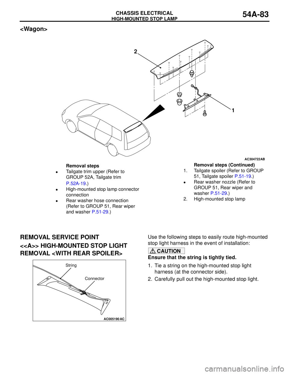
rear light MITSUBISHI LANCER 2005 Workshop Manual
[x] Cancel search | Manufacturer: MITSUBISHI, Model Year: 2005, Model line: LANCER, Model: MITSUBISHI LANCER 2005Pages: 788, PDF Size: 45.98 MB
Page 183 of 788
33-1
GROUP 33
FRONT
SUSPENSION
CONTENTS
GENERAL INFORMATION . . . . . . . .33-2
SERVICE SPECIFICATIONS . . . . . . .33-3
LUBRICANT . . . . . . . . . . . . . . . . . . . .33-3
SPECIAL TOOLS . . . . . . . . . . . . . . . .33-4
ON-VEHICLE SERVICE . . . . . . . . . . .33-5
FRONT WHEEL ALIGNMENT CHECK
AND ADJUSTMENT . . . . . . . . . . . . . . . . . . 33-5
LOWER ARM BALL JOINT AXIAL PLAY
CHECK . . . . . . . . . . . . . . . . . . . . . . . . . . . . 33-6
LOWER ARM BALL JOINT COVER
CHECK . . . . . . . . . . . . . . . . . . . . . . . . . . . . 33-6
STRUT ASSEMBLY . . . . . . . . . . . . . .33-7
REMOVAL AND INSTALLATION . . . . . . . . 33-7
INSPECTION . . . . . . . . . . . . . . . . . . . . . . . . 33-7
DISASSEMBLY AND REASSEMBLY . . . . . 33-8
INSPECTION . . . . . . . . . . . . . . . . . . . . . . . . 33-10
LOWER ARM . . . . . . . . . . . . . . . . . . .33-11
REMOVAL AND INSTALLATION . . . . . . . . 33-11
INSPECTION . . . . . . . . . . . . . . . . . . . . . . . . 33-12
LOWER ARM BALL JOINT COVER
REPLACEMENT . . . . . . . . . . . . . . . . . . . . . 33-12
LOWER ARM BUSHING (REAR)
REPLACEMENT . . . . . . . . . . . . . . . . . . . . . 33-13
STABILIZER BAR* . . . . . . . . . . . . . . .33-14
REMOVAL AND INSTALLATION . . . . . . . . 33-14
INSPECTION . . . . . . . . . . . . . . . . . . . . . . . . 33-17
WARNINGS REGARDING SERVICING OF SUPPLEMENTAL RESTRAINT SYSTEM (SRS) EQUIPPED VEHICLES
WARNING
•Improper service or maintenance of any component of the SRS, or any SRS-related component, can lead to
personal injury or death to service personnel (from inadvertent firing of the air bag) or to the driver and
paassenger (from rendering the SRS inoperative).
•Service or maintenance of any SRS component or SRS-related component must be performed only at an
authorized MITSUBISHI dealer.
•MITSUBISHI dealer personnel must thoroughly review this manual, and especially its GROUP 52B - Supplemental
Restraint System (SRS) before beginning any service or maintenance of any component of the SRS or any
SRS-related component.
NOTE
The SRS includes the following components: SRS air bag control unit, SRS warning light, front impact sensors, air bag module,
clock spring, and interconnecting wiring. Other SRS-related components (that may have to be removed/installed in connection
with SRS service or maintenance) are indicated in the table of contents by an asterisk (*).
Page 213 of 788
Page 245 of 788
ON-VEHICLE SERVICE
POWER STEERING37-11
ON-VEHICLE SERVICE
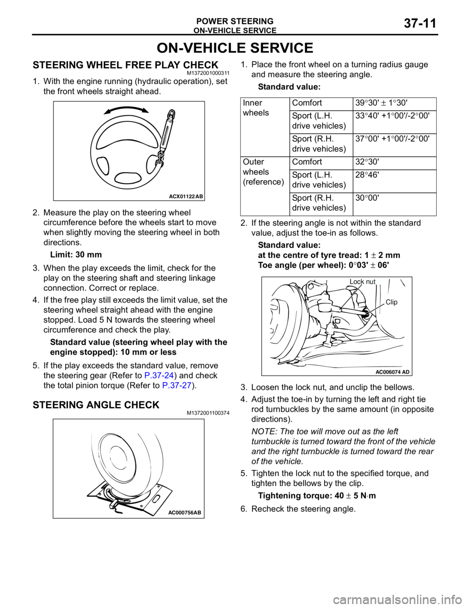
STEERING WHEEL FREE PLAY CHECKM1372001000311
1. With the engine running (hydraulic operation), set
the front wheels straight ahead.
2. Measure the play on the steering wheel
circumference before the wheels start to move
when slightly moving the steering wheel in both
directions.
Limit: 30 mm
3. When the play exceeds the limit, check for the
play on the steering shaft and steering linkage
connection. Correct or replace.
4. If the free play still exceeds the limit value, set the
steering wheel straight ahead with the engine
stopped. Load 5 N towards the steering wheel
circumference and check the play.
Standard value (steering wheel play with the
engine stopped): 10 mm or less
5. If the play exceeds the standard value, remove
the steering gear (Refer to P.37-24) and check
the total pinion torque (Refer to P.37-27).
STEERING ANGLE CHECKM1372001100374
1. Place the front wheel on a turning radius gauge
and measure the steering angle.
Standard value:
2. If the steering angle is not within the standard
value, adjust the toe-in as follows.
Standard value:
at the centre of tyre tread: 1 ± 2 mm
Toe angle (per wheel): 0°03' ± 06'
3. Loosen the lock nut, and unclip the bellows.
4. Adjust the toe-in by turning the left and right tie
rod turnbuckles by the same amount (in opposite
directions).
NOTE: The toe will move out as the left
turnbuckle is turned toward the front of the vehicle
and the right turnbuckle is turned toward the rear
of the vehicle.
5. Tighten the lock nut to the specified torque, and
tighten the bellows by the clip.
Tightening torque: 40 ± 5 N⋅m
6. Recheck the steering angle.
ACX01122
AB
AC000756AB
Inner
wheelsComfort 39°30' ± 1°30'
Sport (L.H.
drive vehicles)33°40' +1°00'/-2°00'
Sport (R.H.
drive vehicles)37°00' +1°00'/-2°00'
Outer
wheels
(reference)Comfort 32°30'
Sport (L.H.
drive vehicles)28°46'
Sport (R.H.
drive vehicles)30°00'
AC006074AD
Lock nut
Clip
Page 306 of 788
DOOR
BODY42-28
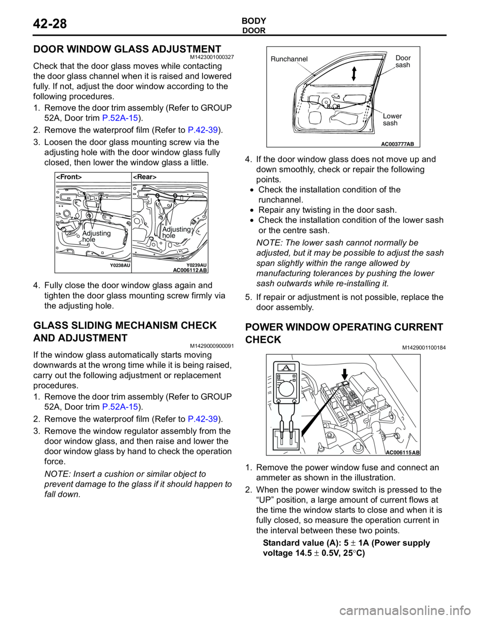
DOOR WINDOW GLASS ADJUSTMENTM1423001000327
Check that the door glass moves while contacting
the door glass channel when it is raised and lowered
fully. If not, adjust the door window according to the
following procedures.
1. Remove the door trim assembly (Refer to GROUP
52A, Door trim P.52A-15).
2. Remove the waterproof film (Refer to P.42-39).
3. Loosen the door glass mounting screw via the
adjusting hole with the door window glass fully
closed, then lower the window glass a little.
4. Fully close the door window glass again and
tighten the door glass mounting screw firmly via
the adjusting hole.
GLASS SLIDING MECHANISM CHECK
AND ADJUSTMENT
M1429000900091
If the window glass automatically starts moving
downwards at the wrong time while it is being raised,
carry out the following adjustment or replacement
procedures.
1. Remove the door trim assembly (Refer to GROUP
52A, Door trim P.52A-15).
2. Remove the waterproof film (Refer to P.42-39).
3. Remove the window regulator assembly from the
door window glass, and then raise and lower the
door window glass by hand to check the operation
force.
NOTE: Insert a cushion or similar object to
prevent damage to the glass if it should happen to
fall down.4. If the door window glass does not move up and
down smoothly, check or repair the following
points.
•Check the installation condition of the
runchannel.
•Repair any twisting in the door sash.
•Check the installation condition of the lower sash
or the centre sash.
NOTE: The lower sash cannot normally be
adjusted, but it may be possible to adjust the sash
span slightly within the range allowed by
manufacturing tolerances by pushing the lower
sash outwards while re-installing it.
5. If repair or adjustment is not possible, replace the
door assembly.
POWER WINDOW OPERATING CURRENT
CHECK
M1429001100184
1. Remove the power window fuse and connect an
ammeter as shown in the illustration.
2. When the power window switch is pressed to the
“UP” position, a large amount of current flows at
the time the window starts to close and when it is
fully closed, so measure the operation current in
the interval between these two points.
Standard value (A): 5 ± 1A (Power supply
voltage 14.5 ± 0.5V, 25°C)
Y0238AUY0239AUAC006112
AB
Adjusting
holeAdjusting
hole
AC003777
RunchannelDoor
sash
Lower
sash
AB
AC006115AB
Page 343 of 788
REAR BUMPER ASSEMBLY
EXTERIOR51-5
REAR BUMPER ASSEMBLY
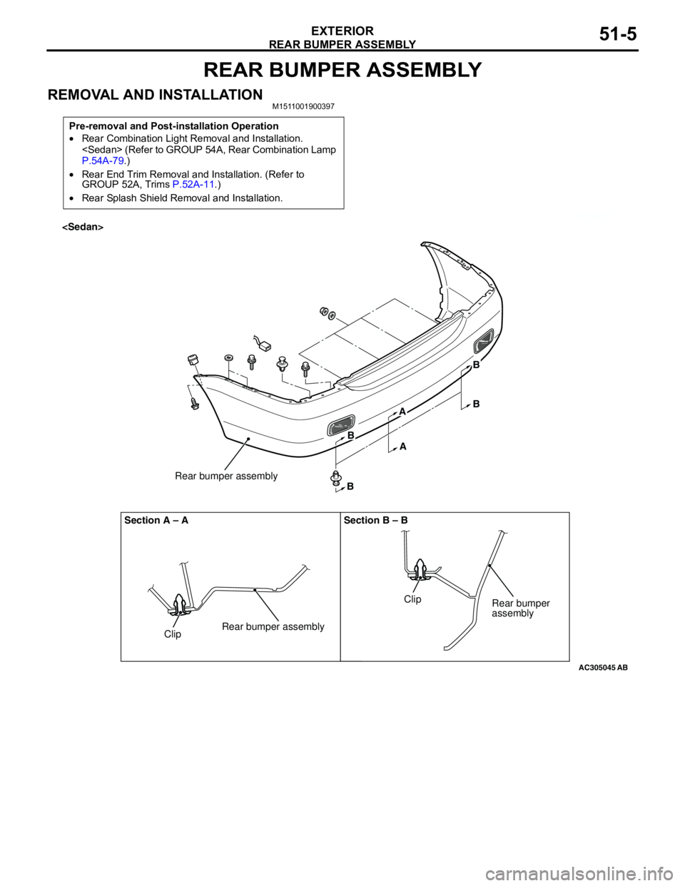
REMOVAL AND INSTALLATIONM1511001900397
Pre-removal and Post-installation Operation
•Rear Combination Light Removal and Installation.
P.54A-79.)
•Rear End Trim Removal and Installation. (Refer to
GROUP 52A, Trims P.52A-11.)
•Rear Splash Shield Removal and Installation.
AC300413
AC305045
ClipRear bumper assemblyRear bumper assembly Section A – A Section B – B
ClipRear bumper
assembly
AB
B
BA
AB
B
Page 357 of 788
TAILGATE SPOILER
EXTERIOR51-19
TAILGATE SPOILER
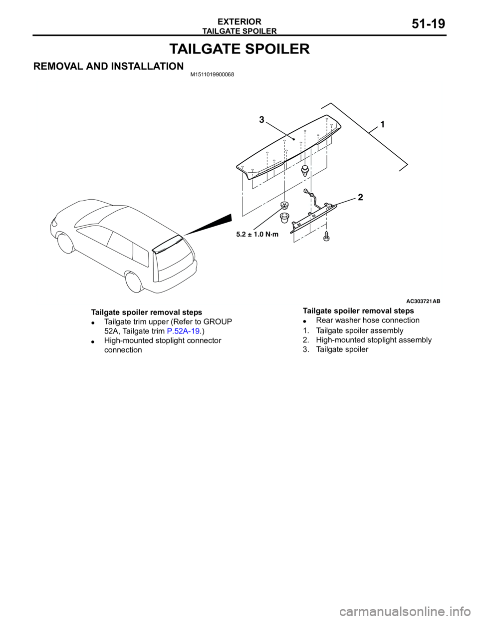
REMOVAL AND INSTALLATIONM1511019900068
AC303721
1
2 3
AB
5.2 ± 1.0 N·m
Tailgate spoiler removal steps
•Tailgate trim upper (Refer to GROUP
52A, Tailgate trim P.52A-19.)
•High-mounted stoplight connector
connection•Rear washer hose connection
1. Tailgate spoiler assembly
2. High-mounted stoplight assembly
3. Tailgate spoiler Tailgate spoiler removal steps
Page 375 of 788
DOOR MIRROR
EXTERIOR51-37
SYMPTOM PROCEDURES
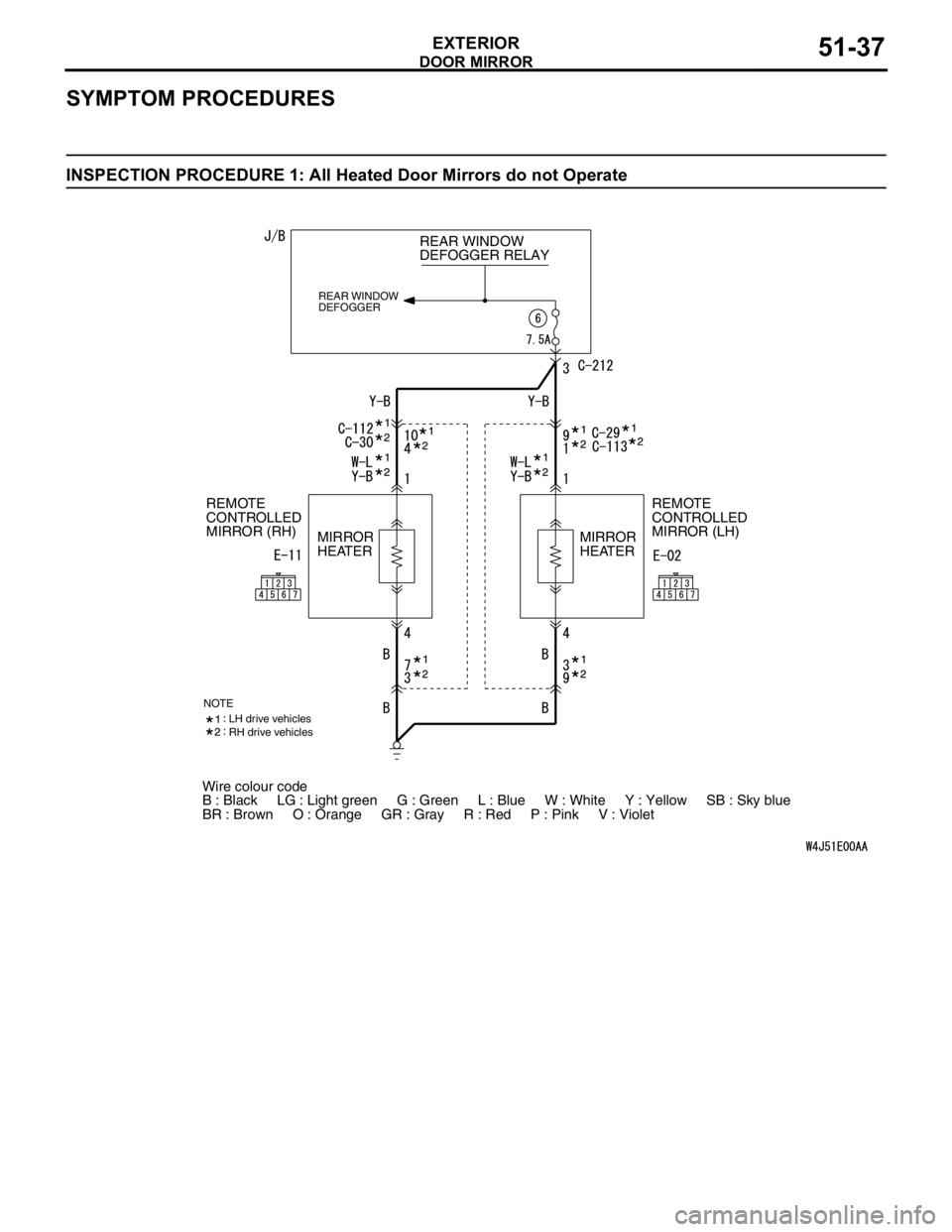
INSPECTION PROCEDURE 1: All Heated Door Mirrors do not Operate
Wire colour code
B : Black LG : Light green G : Green L : Blue W : White Y : Yellow SB : Sky blue
BR : Brown O : Orange GR : Gray R : Red P : Pink V : Violet REAR WINDOW
DEFOGGER RELAY
REAR WINDOW
DEFOGGER
REMOTE
CONTROLLED
MIRROR (LH) REMOTE
CONTROLLED
MIRROR (RH)
MIRROR
HEATERMIRROR
HEATER
NOTELH drive vehicles
RH drive vehicles
Page 377 of 788
DOOR MIRROR
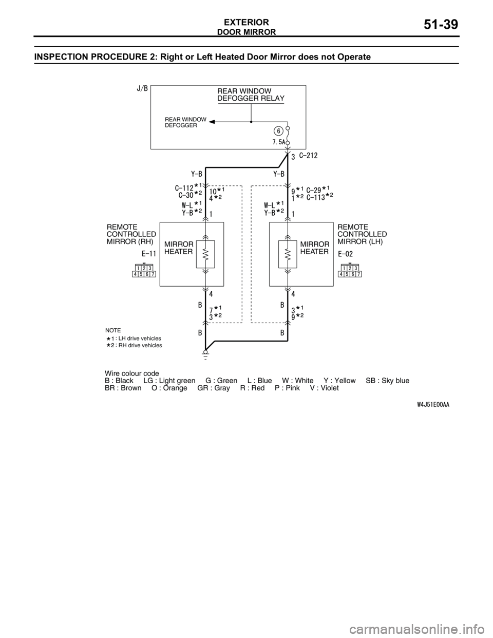
EXTERIOR51-39
INSPECTION PROCEDURE 2: Right or Left Heated Door Mirror does not Operate
Wire colour code
B : Black LG : Light green G : Green L : Blue W : White Y : Yellow SB : Sky blue
BR : Brown O : Orange GR : Gray R : Red P : Pink V : Violet REAR WINDOW
DEFOGGER RELAY
REAR WINDOW
DEFOGGER
REMOTE
CONTROLLED
MIRROR (LH) REMOTE
CONTROLLED
MIRROR (RH)
MIRROR
HEATERMIRROR
HEATER
NOTELH drive vehicles
RH drive vehicles
Page 391 of 788
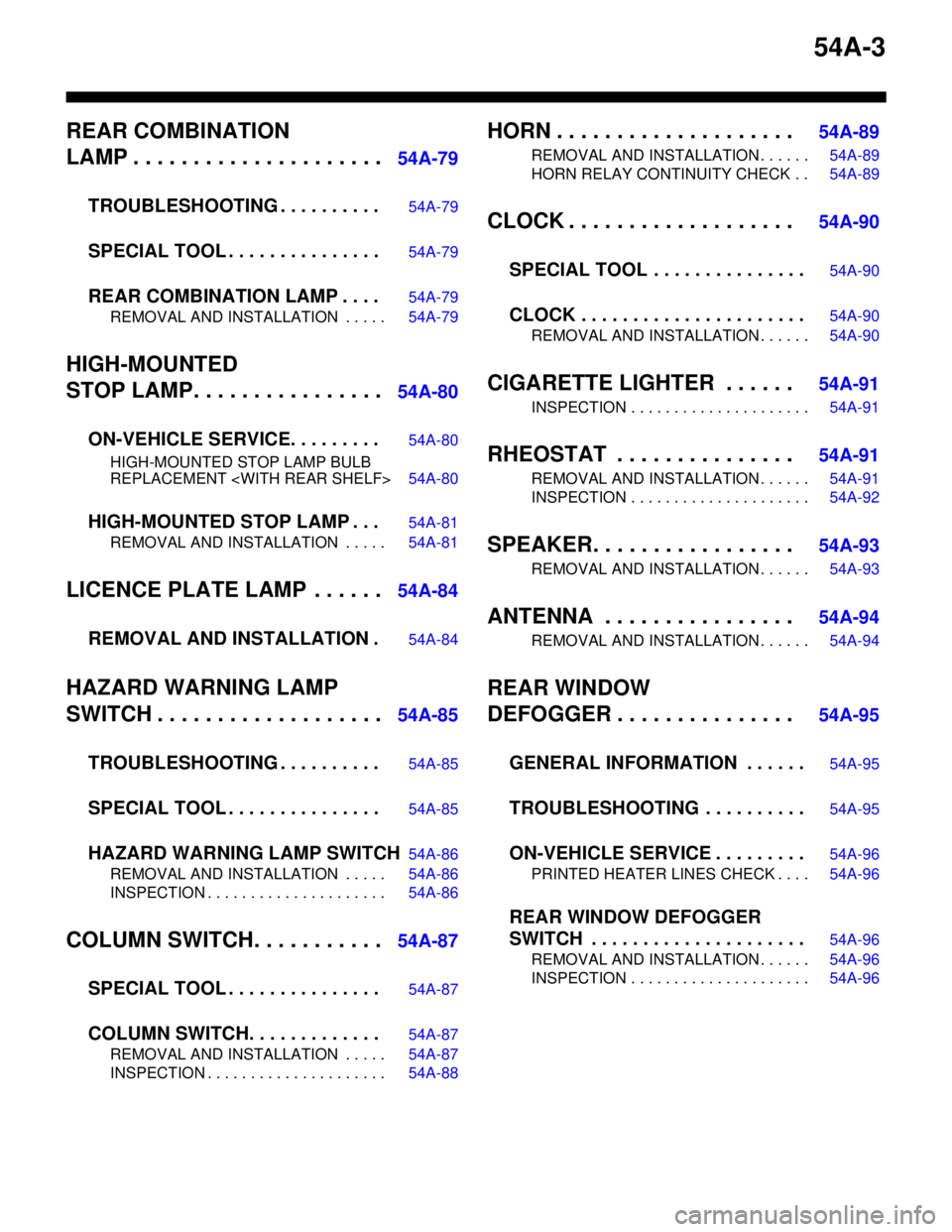
54A-3
REAR COMBINATION
LAMP . . . . . . . . . . . . . . . . . . . . .
54A-79
TROUBLESHOOTING . . . . . . . . . .
54A-79
SPECIAL TOOL . . . . . . . . . . . . . . .54A-79
REAR COMBINATION LAMP . . . .54A-79
REMOVAL AND INSTALLATION . . . . . 54A-79
HIGH-MOUNTED
STOP LAMP. . . . . . . . . . . . . . . .
54A-80
ON-VEHICLE SERVICE. . . . . . . . .
54A-80
HIGH-MOUNTED STOP LAMP BULB
REPLACEMENT
HIGH-MOUNTED STOP LAMP . . .54A-81
REMOVAL AND INSTALLATION . . . . . 54A-81
LICENCE PLATE LAMP . . . . . .54A-84
REMOVAL AND INSTALLATION .
54A-84
HAZARD WARNING LAMP
SWITCH . . . . . . . . . . . . . . . . . . .
54A-85
TROUBLESHOOTING . . . . . . . . . .
54A-85
SPECIAL TOOL . . . . . . . . . . . . . . .54A-85
HAZARD WARNING LAMP SWITCH54A-86
REMOVAL AND INSTALLATION . . . . . 54A-86
INSPECTION . . . . . . . . . . . . . . . . . . . . . 54A-86
COLUMN SWITCH. . . . . . . . . . .54A-87
SPECIAL TOOL . . . . . . . . . . . . . . .
54A-87
COLUMN SWITCH. . . . . . . . . . . . .54A-87
REMOVAL AND INSTALLATION . . . . . 54A-87
INSPECTION . . . . . . . . . . . . . . . . . . . . . 54A-88
HORN . . . . . . . . . . . . . . . . . . . . 54A-89
REMOVAL AND INSTALLATION . . . . . . 54A-89
HORN RELAY CONTINUITY CHECK . . 54A-89
CLOCK . . . . . . . . . . . . . . . . . . . 54A-90
SPECIAL TOOL . . . . . . . . . . . . . . .
54A-90
CLOCK . . . . . . . . . . . . . . . . . . . . . .54A-90
REMOVAL AND INSTALLATION . . . . . . 54A-90
CIGARETTE LIGHTER . . . . . . 54A-91
INSPECTION . . . . . . . . . . . . . . . . . . . . . 54A-91
RHEOSTAT . . . . . . . . . . . . . . . 54A-91
REMOVAL AND INSTALLATION . . . . . . 54A-91
INSPECTION . . . . . . . . . . . . . . . . . . . . . 54A-92
SPEAKER. . . . . . . . . . . . . . . . . 54A-93
REMOVAL AND INSTALLATION . . . . . . 54A-93
ANTENNA . . . . . . . . . . . . . . . . 54A-94
REMOVAL AND INSTALLATION . . . . . . 54A-94
REAR WINDOW
DEFOGGER . . . . . . . . . . . . . . .
54A-95
GENERAL INFORMATION . . . . . .
54A-95
TROUBLESHOOTING . . . . . . . . . .54A-95
ON-VEHICLE SERVICE . . . . . . . . .54A-96
PRINTED HEATER LINES CHECK . . . . 54A-96
REAR WINDOW DEFOGGER
SWITCH . . . . . . . . . . . . . . . . . . . . .
54A-96
REMOVAL AND INSTALLATION . . . . . . 54A-96
INSPECTION . . . . . . . . . . . . . . . . . . . . . 54A-96
Page 471 of 788
