run flat MITSUBISHI LANCER 2005 Workshop Manual
[x] Cancel search | Manufacturer: MITSUBISHI, Model Year: 2005, Model line: LANCER, Model: MITSUBISHI LANCER 2005Pages: 788, PDF Size: 45.98 MB
Page 163 of 788

31-1
GROUP 31
WHEEL AND TYRE
CONTENTS
GENERAL INFORMATION . . . . . . . .31-2
SERVICE SPECIFICATIONS . . . . . . .31-2
TROUBLESHOOTING . . . . . . . . . . . .31-3
DIAGNOSIS . . . . . . . . . . . . . . . . . . . . . . . . 31-3
WHEEL BALANCE ACCURACY . . . . . . . . 31-4
ON-VEHICLE SERVICE . . . . . . . . . . .31-7
TYRE INFLATION PRESSURE CHECK . . . 31-7
TYRE WEAR CHECK . . . . . . . . . . . . . . . . . 31-7
WHEEL RUNOUT CHECK . . . . . . . . . . . . . 31-7
WHEEL AND TYRE . . . . . . . . . . . . . .31-7
INSTALLATION SERVICE POINT . . . . . . . 31-7
Page 169 of 788

ON-VEHICLE SERVICE
WHEEL AND TYRE31-7
ON-VEHICLE SERVICE
TYRE INFLATION PRESSURE CHECKM1311000900312
NOTE: For information on tyre inflation pressure,
refer to the label attached to the centre pillar on the
driver's side.
TYRE WEAR CHECKM1311001000334
Measure the tread depth of the tyres.
Minimum limit: 1.6 mm
If the remaining tread depth is less than the minimum
limit, replace the tyre.
NOTE: When the tread depth of the tyres is reduced
to 1.6 mm or less, wear indicators will appear.
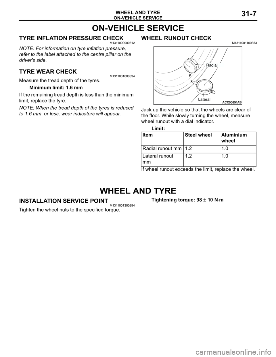
WHEEL RUNOUT CHECKM1311001100353
Jack up the vehicle so that the wheels are clear of
the floor. While slowly turning the wheel, measure
wheel runout with a dial indicator.
Limit:
If wheel runout exceeds the limit, replace the wheel.
WHEEL AND TYRE
INSTALLATION SERVICE POINTM1311001300294
Tighten the wheel nuts to the specified torque.Tightening torque: 98 ± 10 N⋅m Item Steel wheel Aluminium
wheel
Radial runout mm 1.2 1.0
Lateral runout
mm1.2 1.0
ACX00651
ABLateralRadial
Page 227 of 788

LUBRICANTS
PARKING BRAKES36-3
LUBRICANTS
M1361000400293
ON-VEHICLE SERVICE
PARKING BRAKE LEVER STROKE
CHECK AND ADJUSTMENT
M1361000900339
1. Pull the parking brake lever with a force of
approximately 200 N and count the number of
notches.
Standard value: 5 − 7 notches
2. If the parking brake lever stroke is not the
standard value, adjust as described below.
(1) Remove the rear console assembly (Refer to
GROUP 52A, Rear Floor Console P.52A-8).
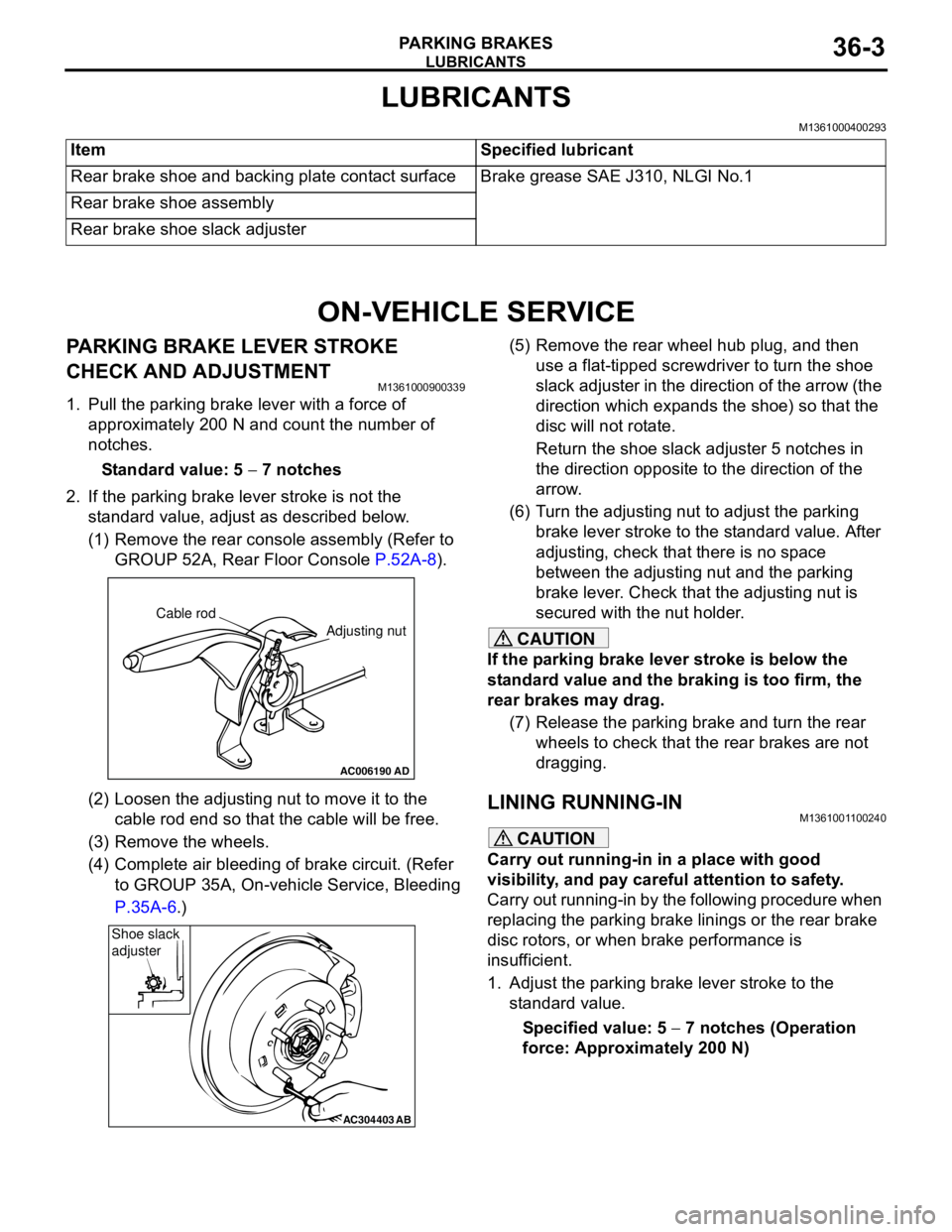
(2) Loosen the adjusting nut to move it to the
cable rod end so that the cable will be free.
(3) Remove the wheels.
(4) Complete air bleeding of brake circuit. (Refer
to GROUP 35A, On-vehicle Service, Bleeding
P.35A-6.)(5) Remove the rear wheel hub plug, and then
use a flat-tipped screwdriver to turn the shoe
slack adjuster in the direction of the arrow (the
direction which expands the shoe) so that the
disc will not rotate.
Return the shoe slack adjuster 5 notches in
the direction opposite to the direction of the
arrow.
(6) Turn the adjusting nut to adjust the parking
brake lever stroke to the standard value. After
adjusting, check that there is no space
between the adjusting nut and the parking
brake lever. Check that the adjusting nut is
secured with the nut holder.
CAUTION
If the parking brake lever stroke is below the
standard value and the braking is too firm, the
rear brakes may drag.
(7) Release the parking brake and turn the rear
wheels to check that the rear brakes are not
dragging.
LINING RUNNING-INM1361001100240
CAUTION
Carry out running-in in a place with good
visibility, and pay careful attention to safety.
Carry out running-in by the following procedure when
replacing the parking brake linings or the rear brake
disc rotors, or when brake performance is
insufficient.
1. Adjust the parking brake lever stroke to the
standard value.
Specified value: 5 − 7 notches (Operation
force: Approximately 200 N) Item Specified lubricant
Rear brake shoe and backing plate contact surface Brake grease SAE J310, NLGI No.1
Rear brake shoe assembly
Rear brake shoe slack adjuster
AC006190
Cable rod
Adjusting nut
AD
AC304403AB
Shoe slack
adjuster
Page 247 of 788

ON-VEHICLE SERVICE
POWER STEERING37-13
STEERING WHEEL RETURN TO CENTRE
CHECK
M1372001800317
Conduct a road test:
1. Make both gradual and sudden turns and check
the steering wheel return.
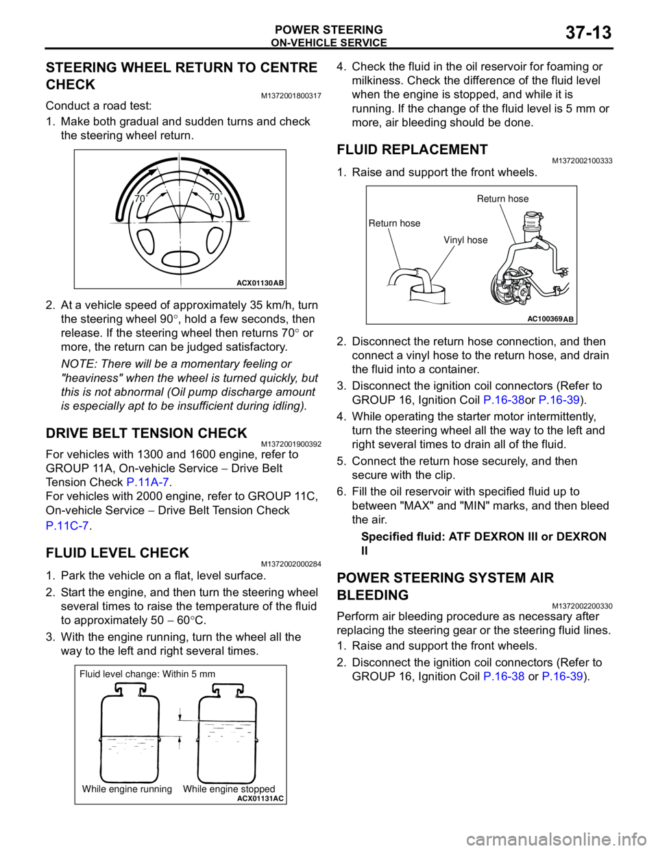
2. At a vehicle speed of approximately 35 km/h, turn
the steering wheel 90°, hold a few seconds, then
release. If the steering wheel then returns 70° or
more, the return can be judged satisfactory.
NOTE: There will be a momentary feeling or
"heaviness" when the wheel is turned quickly, but
this is not abnormal (Oil pump discharge amount
is especially apt to be insufficient during idling).
DRIVE BELT TENSION CHECKM1372001900392
For vehicles with 1300 and 1600 engine, refer to
GROUP 11A, On-vehicle Service − Drive Belt
Tension Check P.11A-7.
For vehicles with 2000 engine, refer to GROUP 11C,
On-vehicle Service − Drive Belt Tension Check
P.11C-7.
FLUID LEVEL CHECKM1372002000284
1. Park the vehicle on a flat, level surface.
2. Start the engine, and then turn the steering wheel
several times to raise the temperature of the fluid
to approximately 50 − 60°C.
3. With the engine running, turn the wheel all the
way to the left and right several times.4. Check the fluid in the oil reservoir for foaming or
milkiness. Check the difference of the fluid level
when the engine is stopped, and while it is
running. If the change of the fluid level is 5 mm or
more, air bleeding should be done.
FLUID REPLACEMENTM1372002100333
1. Raise and support the front wheels.
2. Disconnect the return hose connection, and then
connect a vinyl hose to the return hose, and drain
the fluid into a container.
3. Disconnect the ignition coil connectors (Refer to
GROUP 16, Ignition Coil P.16-38or P.16-39).
4. While operating the starter motor intermittently,
turn the steering wheel all the way to the left and
right several times to drain all of the fluid.
5. Connect the return hose securely, and then
secure with the clip.
6. Fill the oil reservoir with specified fluid up to
between "MAX" and "MIN" marks, and then bleed
the air.
Specified fluid: ATF DEXRON III or DEXRON
II
POWER STEERING SYSTEM AIR
BLEEDING
M1372002200330
Perform air bleeding procedure as necessary after
replacing the steering gear or the steering fluid lines.
1. Raise and support the front wheels.
2. Disconnect the ignition coil connectors (Refer to
GROUP 16, Ignition Coil P.16-38 or P.16-39).
ACX01130
AB
70˚70˚
ACX01131While engine running While engine stoppedAC
Fluid level change: Within 5 mm
AC100369AB
Return hoseReturn hose
Vinyl hose
Page 459 of 788

FOG LAMP
CHASSIS ELECTRICAL54A-71
FOG LAMP
SERVICE SPECIFICATIONM1542000300343
SPECIAL TOOLM1542000600894
TROUBLESHOOTINGM1542000701292
When the front fog lamp switch is turned to ON with
the tail lamp or the headlamp on (the tail lamp switch
or the headlamp switch is ON), the fog lamp relay
turns on, and the fog lamps will illuminate.
If the tail lamps or the headlamps are turned off with
the lighting switch OFF while the fog lamps are on,
the front fog lamps turn off at the same time to
prevent unattended operation.
If the tail lamps are turned off by the headlamp
automatic shutdown function, the fog lamps turn off
at the same time. However, if the tail lamps illuminate
again, the fog lamps do not.
The front fog lamps are controlled by the Smart
Wiring System (SWS). For troubleshooting, refer to
respective Groups below.
•Not using SWS monitor: GROUP 54B, SWS
Troubleshooting P.54B-38.
•Using SWS monitor: GROUP 54C, SWS
Troubleshooting P.54C-22.
ON-VEHICLE SERVICE
FRONT FOG LAMP AIMING CHECKM1542001100438
After setting the vehicles to the following condition,
adjust the front fog lamp aiming.
•Check that the tyre inflation pressure is at the
value indicated on the tyre pressure labels.
•Set the vehicle to the unladen condition and park
it on a level surface.
•Have a single person (approximately 75 kg) sit in
the driver’s seat.•Run the engine at a speed of 2000 r/min to fully
charge the battery.
Turn on the front fog lamps and check that the
illumination is within the standard value range.
Standard value: Illuminates to within 40
metres
CAUTION
For the fog lamp which is not being measured,
disconnect that fog lamp’s connector if possible
so that it does not illuminate while carrying out
the adjustment. Furthermore, make sure that the
light axis does not get shifted when
re-connecting the connector.
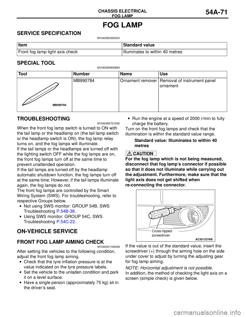
If the value is out of the standard value, insert the
screwdriver (+) through the aiming hole on the side
under cover to adjust by turning the adjusting gear
for fog lamp aiming.
NOTE: Horizontal adjustment is not possible.
In addition, the method of checking the light axis on a
screen (simple check) is given below. Item Standard value
Front fog lamp light axis check Illuminates to within 40 metres
Tool Number Name Use
MB990784 Ornament remover Removal of instrument panel
ornament
MB990784
AC301337
Cross-tipped
screwdriver
AB