Condition MITSUBISHI LANCER 2006 User Guide
[x] Cancel search | Manufacturer: MITSUBISHI, Model Year: 2006, Model line: LANCER, Model: MITSUBISHI LANCER 2006Pages: 800, PDF Size: 45.03 MB
Page 97 of 800
IGNITION SYSTEM
ENGINE ELECTRICAL16-35
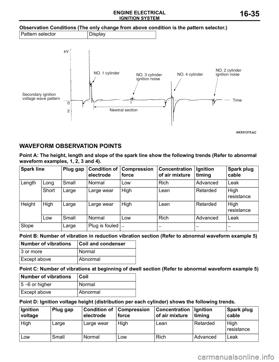
Observation Conditions (The only change from above condition is the pattern selector.)
Pattern selectorDisplay
AKX01275
kV
Secondary ignition
voltage wave pattern 0
2NO. 1 cylinder
NO. 3 cylinder
ignition noise
Newtral section NO. 4 cylinder
NO. 2 cylinder
ignition noise
Time
AC
WA VEFORM OBSER V A T ION POINTS
Point A: The he ight, len g th and s l ope of th e sp a r k line sho w the following trends (Re f er to abnorma l
wave
form exam ples, 1 , 2, 3 a nd 4).
Spark linePlug gapCondition of
electrodeCompression
force Concentration
of air mixtureIgnition
timingSpark plug
cable
LengthLongSmallNormalLowRichAdvancedLeak
ShortLargeLarge wearHigh LeanRetardedHigh
resistance
HeightHighLargeLarge wearHighLeanRetardedHigh
resistance
LowSmallNormalLow RichAdvancedLeak
SlopeLargePlug is fouled−−−−
Point B: Number of v i bra t ion in red uction vi bra t ion sec tion (Refer to a bnormal wavefo r m examp l e 5)
Number of vibrationsCoil and condenser
3 or moreNormal
Except aboveAbnormal
Point C: Number of v i bra t ions a t beginnin g of dwell se ction (Refer to a bnormal wave form exam ple 5)
Number of vibrationsCoil
5 − 6 or higherNormal
Except aboveAbnormal
Point D: Ignition volt a g e height (distribution per each cylinder) s hows the follo wing tren ds.
Ignition
voltagePlug gapCondition of
electrodeCompression
forceConcentration
of air mixtureIgnition
timingSpark plug
cable
HighLargeLarge wearHighLeanRetardedHigh
resistance
LowSmallNormalLowRichAdvancedLeak
Page 117 of 800
EMISSION CONTROL
ENGINE AND EMISSION CONTROL17-11
2. Plug the nipple from which the vacuum hose was removed.
3. When the engine is cold or hot, apply a vacuum of 53 kPa, and check the condition of the vacuum.
When engine is cold
(Engine coolant temperature: 40°C or less)
Engine conditionNormal condition
At idleVacuum is maintained.
3,000 r/min
When engine is hot
(Engine coolant temperature: 80°C or higher)
Engine conditionNormal condition
At idleVacuum is maintained.
3,000 r/min (within 3
minutes after engine
starts)Vacuum will leak.
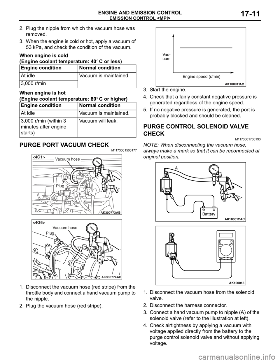
PURGE PORT VACUUM CHECKM1173001500177
AK300773
<4G1>
AB
Plug
Vacuum hose
AK300774
<4G6>
AB
Plug
Vacuum hose
1.Disco nnect th e vacuum ho se (red st ripe) from the
throttle body and connect a hand vacuum pump to
th e nip p le.
2.Plu g the vacuum hose (red stripe).
AK100011AC
Vac-
uum
Engine speed (r/min)
3.S t art the engine.
4.Check t hat a f a irly co nst ant n egative p r essure is
g enerate d regard l ess of the en gine spee d.
5.If no neg ative pressur e is genera t ed, th e port is
p r obably blocked an d sh ould be cleane d.
PURGE CONTROL SOLENOID VA L V E
CHECK
M1173 0017 0019 3
NOTE: Whe n discon nect i ng th e va cuum hose,
always make a mark so th at it can be reconnected at
original p o sition.
AK100012AC
Battery
A
AK100013
1.
Disco nnect the vacu um h o se f r om th e solenoid
valve.
2.Disco nnect the ha rness connector .
3.Con nect a ha nd vacu um pump to nipp le (A) of the
solen o id valve (ref e r to th e ill ust r ation at le f t ).
4.Check a i rtig htness b y app lying a vacuum with
volt age applied d i rectly from t he batt e ry to the
p u rge con t rol so leno id valve an d without app lying
volt age .
Page 118 of 800
Battery voltageNormal condition
AppliedVacuum leaks
Not appliedVacuum maintained
EMISSION CONTROL
ENGINE AND EMISSION CONTROL17-12
5. Measure the resistance between the terminals of the solenoid valve.
Standard value: 30 − 34 Ω (at 20°C)
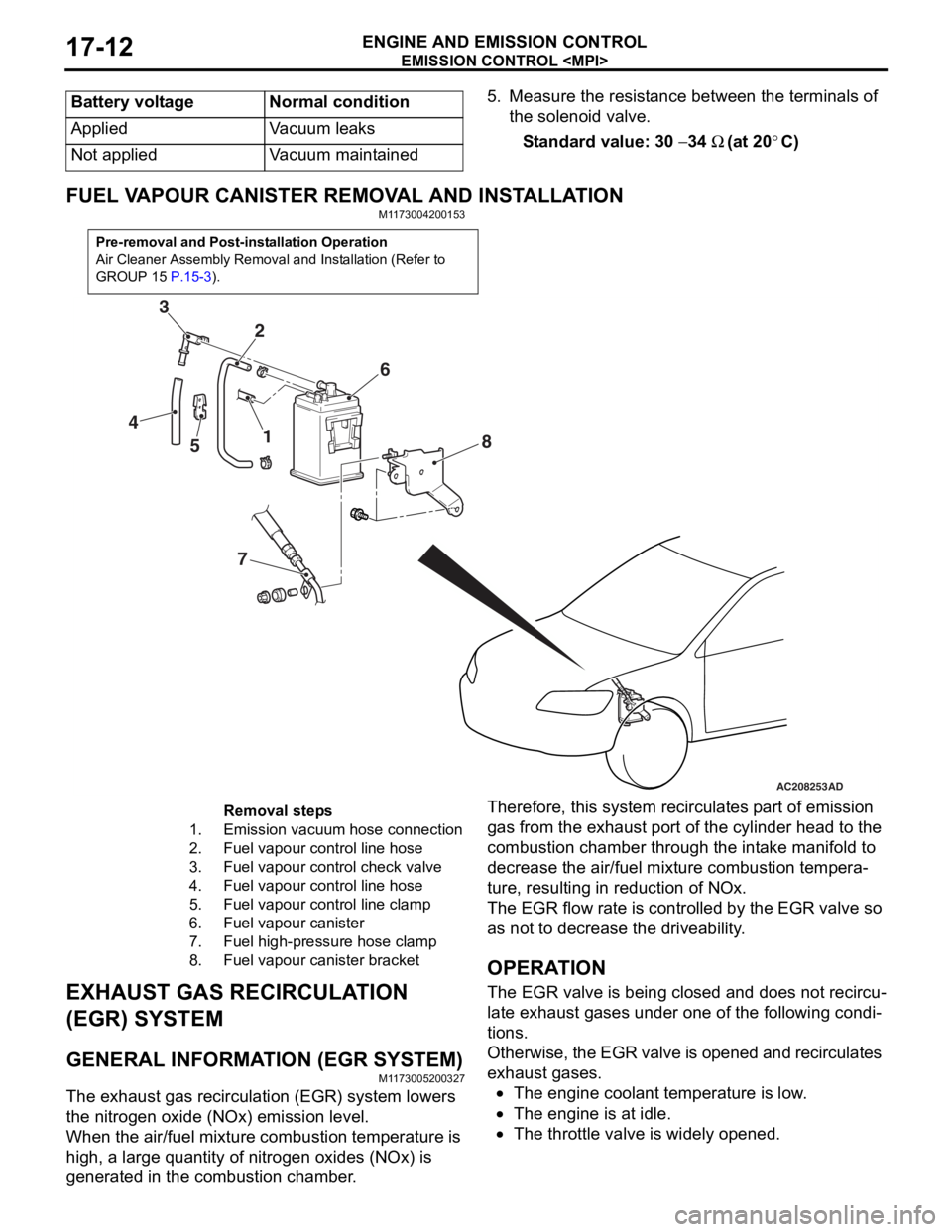
FUEL VAPOUR CANISTER RE MOVAL AND INSTALLATION
M1173004200153
Pre-removal and Post-installation Operation
Air Cleaner Assembly Removal and Installation (Refer to
GROUP 15
P.15-3).
AC208253
1
2
3
4 5 6
7 8
AD
Removal steps
1.Emission vacuum hose connection
2.Fuel vapour control line hose
3.Fuel vapour control check valve
4.Fuel vapour control line hose
5.Fuel vapour control line clamp
6.Fuel vapour canister
7.Fuel high-pressure hose clamp
8.Fuel vapour canister bracket
EXHAUST GAS RECIRCULA
T ION
(EGR) SYSTEM
GENERAL INFORMAT ION (EGR SYSTEM)
M1173 0052 0032 7
The exhaust gas recircu l atio n (EGR) system lowers
the nitrogen
oxide (NOx) emission level.
When the air/fuel mixture combus tio n temp erature is
high,
a larg e qua ntity of nitrogen oxides (NOx) is
generat
ed in the comb ustion chamb e r .
Therefor e, this syst em re circulat es p a rt o f emission
gas fro
m the e x ha ust po rt of the cylinder h ead to th e
combust
i on chamber thro ugh th e int a ke ma nifold to
decre
ase the air/fuel mixture combust i on te mpera
-
ture, resulting in redu ctio n of NOx.
The EGR flow rate is cont rolle d by the EGR valve so
as no
t to de crease the driveability .
OPERAT ION
The EGR valve is being clos ed an d does not re circu-
late ex hau st ga ses unde r one o f the fo llo wing condi-
tions.
Otherwise, th e EGR va lve is opene d an d recircul ates
exha
ust g a ses.
•The engine coolan t temperature is low .
•The engine is at idle.
•The throttle va lve is widely ope ned.
Page 121 of 800
EMISSION CONTROL
ENGINE AND EMISSION CONTROL17-15
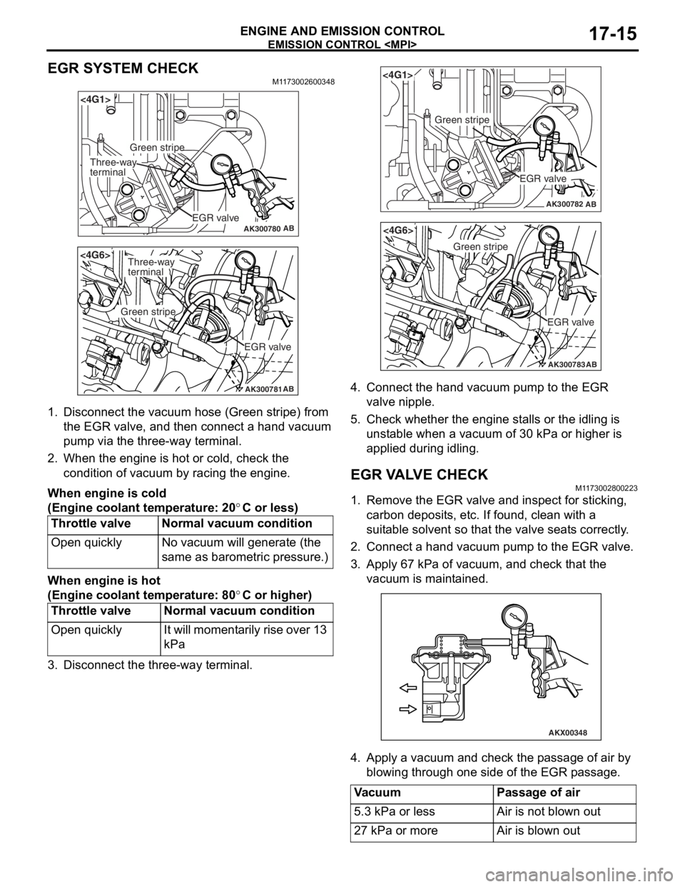
EGR SYSTEM CHECK
M1173002600348
AK300780AB
<4G1>
EGR valve
Green stripe
Three-way
terminal
AK300781AB
<4G6>
EGR valve
Green stripe
Three-way
terminal
1.Disco nnect the vacu um ho se (Green stripe) from
th e EGR valve, a nd th en connect a hand vacuum
pu mp via t he thre e-way te rmin al.
2.Wh en the engine is hot o r cold, check the
condition of va cuum by racing the engine.
When engine is c o ld
(Eng ine coo lant tem perature: 20°C or less)
Throttle valveNormal vacuum co ndition
Open quicklyNo va cuum will gene rate (th e
same as baro
m etric pre s sure.)
When engine is h o t
(Eng ine coo lant tem perature: 80°C or higher)
Throttle valveNormal vacuum c ondition
Open quicklyIt will mo me nt a r i l y rise o v er 13
kPa
3.Disco nnect the th ree-way t e rminal.
AK300782AB
<4G1>
EGR valve
Green stripe
AK300783AB
<4G6>
EGR valve
Green stripe
4.Conn ect the han d va cuum pump to t he EGR
valve nipple.
5.Check whe t her th e engine st alls or the idling is
u n st able when a vacuum of 30 kPa or h i gher is
a pplied during idling.
EGR V A L V E CHECKM1173 0028 0022 3
1.Remove the EGR valve an d inspect for stickin g ,
carbon deposit s, e t c. If found , clean with a
suit able so lve n t so that th e va lve seat s corre ctly .
2.Conn ect a hand vacuum pump to the EGR va lve .
3.App l y 6 7 kPa of va cuum, and check t hat the
vacu um is maint a ined.
AKX00348
4.App l y a vacuum and chec k th e p a ssage of air by
b l owing throug h one side of the EGR p a ssage.
VacuumPassage of air
5.3 kPa or lessAir is not blown out
27 kPa or moreAir is blown out
Page 122 of 800
EMISSION CONTROL
ENGINE AND EMISSION CONTROL17-16
5. Replace the gasket, and tighten to the specified torque.
Tightening torque:
<4G1> 21 ± 4 N⋅m
<4G6> 20 ± 2 N⋅m
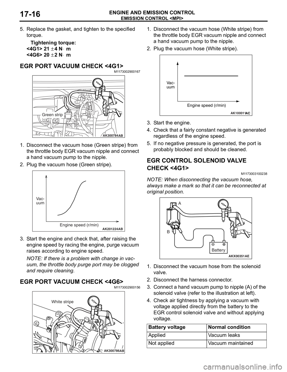
EGR PORT VACUUM CHECK <4G1>M1173002900167
AK300784AB
Green strip
1.Disco nnect the vacu um ho se (Green stripe) from
th e t h ro tt le b o d y EGR va cuu m ni pp le an d co nn ec t
a hand vacu um p u mp to the nipple.
2.Plu g the vacuum hose (Gree n stripe).
AK201224AB
Vac-
uum
Engine speed (r/min)
3.S t art the engin e and check t hat, af ter ra ising th e
engine spe ed by ra cin g the e ngine, p u rge vacuu m
raises according to engine speed.
NOTE: If ther e is a prob lem with change in vac-
uum, the t h rottle bod y p u rge port may be clo gged
an
d requ ire clean ing.
EGR PORT VA CUUM CHECK <4G6>M1173 0029 0015 6
AK300786AB
White stripe
1.Disco nnect the vacu um h o se (W hite strip e ) from
th e t h ro tt le b o d y EGR va cuu m ni pp le an d co nn ec t
a hand vacuum p u mp to the nipple.
2.Plug the vacuum hose (White stripe).
AK100011AC
Vac-
uum
Engine speed (r/min)
3.S t art the engine.
4.Check that a fairly const a nt n egative is gene rated
re gardle s s of the engine sp eed.
5.If no neg ative pressur e is genera t ed, th e port is
p r obably blocked an d sh ould be cleane d.
EGR CONTROL SOLENOID VA L V E
CHECK <
4 G1 >
M1173 0031 0023 8
NOTE: Whe n discon nect i ng th e va cuum hose,
always make a mark so th at it can be reconnected at
original p o sition.
AKX00351
A
B
AE
Battery
1. Disco nnect the vacu um h o se f r om th e solenoid
valve.
2.Disco nnect the ha rness connector .
3.Con nect a ha nd vacu um pump to nipp le (A) of the
solen o id valve (ref e r to th e ill ust r ation at le f t ).
4.Check a i r tightness b y ap plying a vacuum with
volt age applied d i rectly from t he batt e ry to the
EGR cont rol solen o id valve and withou t applyin g
volt age .
Battery voltageNormal condition
AppliedVa c u u m l e a k s
Not appliedVacuum maintained
Page 123 of 800
AKX00352
EMISSI ON CONTROL
ENGINE AND E M ISSION CON T R O L17-17
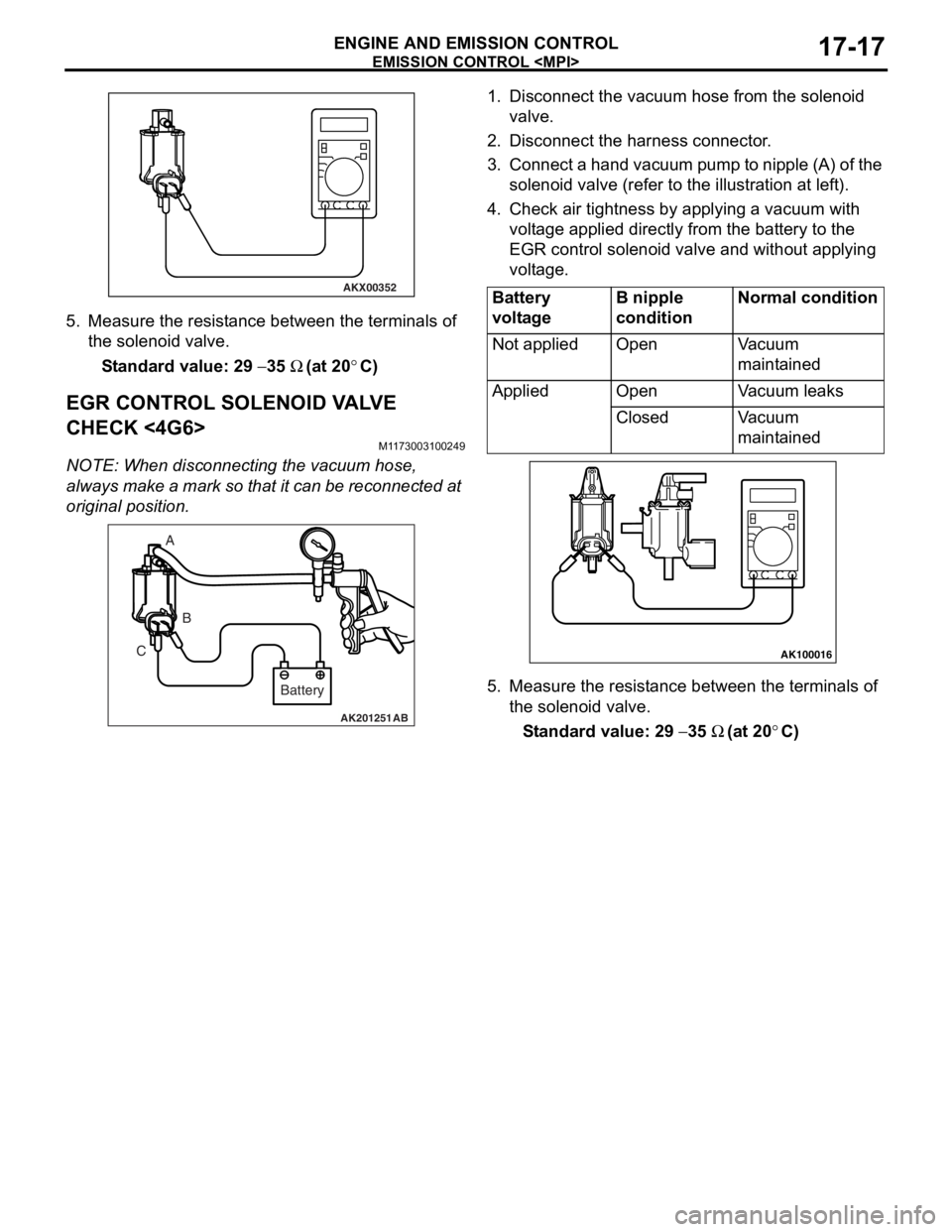
5.Measure the resist ance between the te rmin als of
th e solenoid va lve .
St andard va lue: 29 − 35 Ω (at 20°C)
EGR CONTROL SOLENOID V A L V E
CHECK <
4 G6>
M1173 0031 0024 9
NOTE: Whe n discon nect i ng th e va cuum hose,
always
make a mark so th at it can be reconnected at
original p o sition.
AK201251AB
A
B
C
Battery
1.Disco nnect the vacu um h o se f r om th e solenoid
valve.
2.Disco nnect the ha rness connector .
3.Con nect a ha nd vacu um pump to nipp le (A) of the
solen o id valve (ref e r to th e ill ust r ation at le f t ).
4.Check a i r tightness b y ap plying a vacuum with
volt age applied d i rectly from t he batt e ry to the
EGR cont rol solen o id valve and withou t applyin g
volt age .
Battery
voltageB nipple
conditionNormal condition
Not appliedOpenVacuum
maintained
AppliedOpenVacuum leaks
ClosedVacuum
maintained
AK100016
5.Measure the resist ance betwee n the te rminals of
th e so lenoid valve .
St andard va lue: 29 − 35 Ω (at 20°C)
Page 178 of 800
CROSSMEMBER
POWER PLANT MOUNT32-8
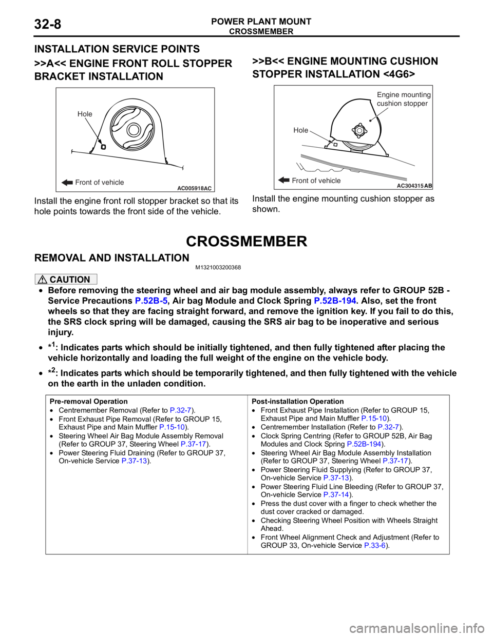
INSTALLATION SERVICE POINTS
>>A<< ENGINE FRONT ROLL STOPPER
BRACKET INSTALLATION
AC005918Front of vehicleHoleAC
Inst
all th e en gine fron t roll stop per b r acket so that it s
hole
point s towards the fro n t side of the vehicle.
>>B<< ENGINE MOUNTING CUSHION
ST
OPPER INST ALLA TION <4G6>
AC304315ABFront of vehicle
Hole Engine mounting
cushion stopper
Inst
all the e ngin e mo untin g cushio n sto pper a s
shown.
CROSSMEMBER
REMOVA L AND INST ALLA TIONM13210032 0036 8
CAUTION
•Before removing the steering wheel and air bag module assembly, always refer to GROUP 52B -
Service Precautions
P.52B-5, Air bag Module and Clock Spring P.52B-194. Also, set the front
wheels so that they are facing straight forward, and remove the ignition key. If you fail to do this,
the SRS clock spring will be damaged, causing the SRS air bag to be inoperative and serious
injury.
•*1: Indicates parts which should be initially tightened, and then fully tightened after placing the
vehicle horizontally and loading the full weight of the engine on the vehicle body.
•
Pre-removal Operation
•Centremember Removal (Refer to P.32-7).
•Front Exhaust Pipe Remova l (Refer to GROUP 15,
Exhaust Pipe and Main Muffler P.15-10).
•Steering Wheel Air Bag Mo dule Assembly Removal
(Refer to GROUP 37, Steering Wheel P.37-17).
•Power Steering Fluid Draining (Refer to GROUP 37,
On-vehicle Service P.37-13).
Post-installation Operation
•Front Exhaust Pipe Installation (Refer to GROUP 15,
Exhaust Pipe and Main Muffler
P.15-10).
•Centremember Installation (Refer to P.32-7).
•Clock Spring Centring (Refer to GROUP 52B, Air Bag
Modules and Clock Spring P.52B-194).
•Steering Wheel Air Bag Module Assembly Installation
(Refer to GROUP 37, Steering Wheel P.37-17).
•Power Steering Fluid Supplying (Refer to GROUP 37,
On-vehicle Service P.37-13).
•Power Steering Fluid Line Bleeding (Refer to GROUP 37,
On-vehicle Service P.37-14).
•Press the dust cover with a finger to check whether the
dust cover cracked or damaged.
•Checking Steering Wheel Position with Wheels Straight
Ahead.
•Front Wheel Alignment Check and Adjustment (Refer to
GROUP 33, On-vehicle Service P.33-6).
*2: Indicates parts which should be temporarily tightened, and then fully tightened with the vehicle
on the earth in the unladen condition.
Page 188 of 800
ON-VEHICLE SERVICE
FRONT SUSPENSION33-6
ON-VEHICLE SERVICE
FRONT WHEEL ALIGNMENT CHECK AND
ADJUSTMENT
M1331000900886
Measure wheel alignment with alignment equipment
on a level surface. The front suspension, steering
system, wheels, and tyres should be serviced to nor
-
mal condition before measuring wheel alignment.
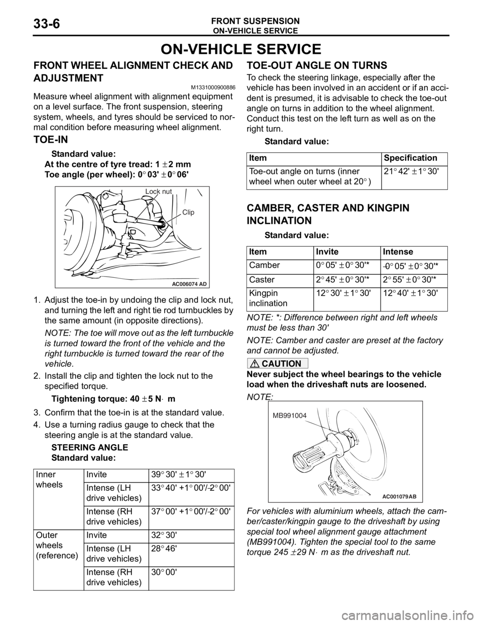
TOE-IN
Standard value:
At the centre of tyre tread: 1 ± 2 mm
Toe angle (per wheel): 0°03' ± 0°06'
AC006074 AD
Lock nut
Clip
1.Adjust the to e-in by undoing th e clip and lock nut,
and turning th e lef t and rig h t tie rod turnbu ckles by
th e same amount (in op posite direct ions).
NOTE: The toe will move out as th e lef t turnbuckle
is turn
ed toward the fro n t of th e ve hicle an d the
right tu
rnbuckle is turned t o ward the rear of the
vehicle.
2. In st all the clip and tighten the lock nut to the
specifie d torqu e .
Ti ghte n ing torque: 40 ± 5 N⋅m
3.Conf irm t hat the toe-in is at the st anda rd value.
4.Use a turn ing ra dius gaug e to check tha t the
steering ang le is at the st an dard value .
STEE R I N G AN G L E
St andard va lue:
Inner
wheelsInvite39°30' ± 1°30'
Intense (LH
drive vehicles)33°40' +1°00'/−2°00'
Intense (RH
drive vehicles)37°00' +1°00'/−2°00'
Outer
wheels
(reference)Invite32°30'
Intense (LH
drive vehicles)28°46'
Intense (RH
drive vehicles)30°00'
TO E-OUT ANGLE ON TURNS
To check the stee ring linkage, e s pe cially af ter the
vehicle has been invo
lve d in an accid ent or if an a cci
-
dent is pres umed, it is advisab le to check th e toe-ou t
angle
on tu rns in addition to the wh eel a lig nmen t.
Conduct this test on th e lef t tu rn as we ll a s on the
right turn.
St andard va lue:
ItemSpecification
Toe-out angle on turns (inner
wheel when outer wheel at 20
°)
21°42' ± 1°30'
CAMBER, CASTER AND KINGPIN
INCLINA
T ION
St andard va lue:
ItemInviteIntense
Camber0°05' ± 0°30'*−0°05' ± 0°30'*
Caster2°45' ± 0°30'*2°55' ± 0°30'*
Kingpin
inclination12°30' ± 1°30'12°40' ± 1°30'
NOTE: *: Diffe rence between right and lef t wheels
must be less than 30'
NOTE: Camber and caster are prese t at th e factory
and cannot be adjust ed.
CAUTION
Never subject the wheel bearings to the vehicle
load when the driveshaft nuts are loosened.
NOTE:
AC001079
MB991004
AB
For vehicles with aluminium wheels, attach the cam-
ber/caster/kingpin gauge to the driveshaft by using
special tool wheel alignment gauge attachment
(MB991004). Tighten the special tool to the same
torque 245
± 29 N⋅m as the driveshaft nut.
Page 193 of 800
LOWER ARM
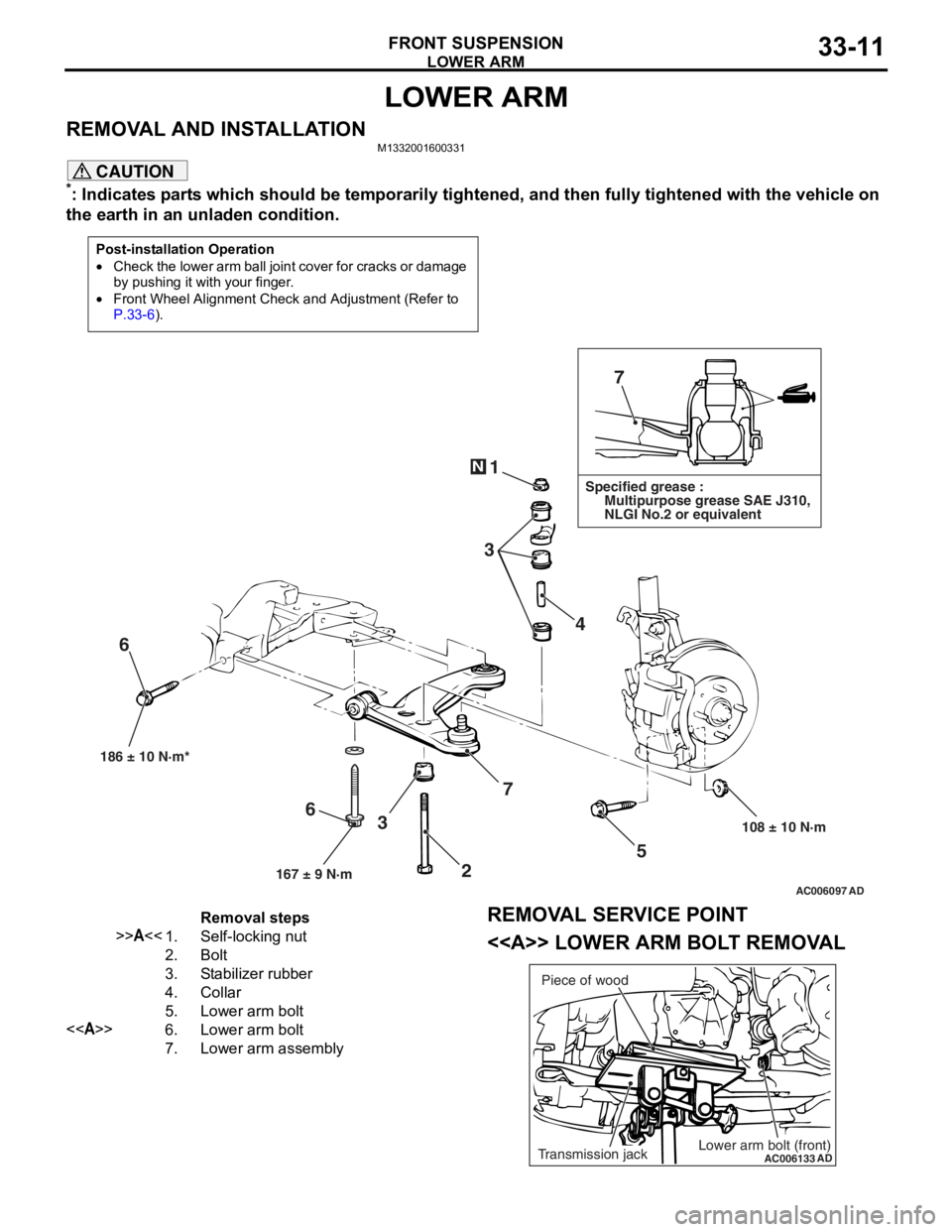
FRONT SUSPENSION33-11
LOWER ARM
REMOVAL AND INSTALLATIONM1332001600331
CAUTION
*: Indicates parts which should be temporarily tightened, and then fully tightened with the vehicle on
the earth in an unladen condition.
Post-installation Operation
•Check the lower arm ball join t cover for cracks or damage
by pushing it with your finger.
•Front Wheel Alignment Check and Adjustment (Refer to
P.33-6).
AC006097 AD
7
1
3 4
5
108 ± 10 N·m
186 ± 10 N·m*
7
3
6
N
Specified grease :
Multipurpose grease SAE J310,
NLGI No.2 or equivalent
167 ± 9 N·m
6
2
Removal steps
>>A<<1.Self-locking nut
2.Bolt
3.Stabilizer rubber
4.Collar
5.Lower arm bolt
<>6.Lower arm bolt
7.Lower arm assembly
REMOVAL SERVICE POINT
<> LOWER ARM BOLT REMOVAL
AC006133
ADLower arm bolt (front)Transmission jackPiece of wood
Page 204 of 800
ON-VEHICLE SERVICE
REAR SUSPENSION34-6
ON-VEHICLE SERVICE
REAR WHEEL ALIGNMENT CHECK AND
ADJUSTMENT
M1341011000372
Measure wheel alignment with an alignment equip-
ment on level earth.
The rear suspension, wheels, and tyres should be
serviced to the normal condition prior to wheel align
-
ment measurement.
CAMBER
Standard value: −0°40' ± 0°30' (Left/right devi-
ation within 30')
CAUTION
Never subject the wheel bearings to the vehicle
load when the rear wheel hub nuts (self-locking
nuts) or special tool wheel alignment gauge
attachment (MB991014) are loosened.
NOTE:
AC001079
MB991014
AG
For vehicles with aluminium wheels, attach the cam-
ber/caster/kingpin gauge to the trailing arm spindle
by using special tool wheel alignment gauge attach
-
ment (MB991014). Tighten the special tool to the
same torque 175
± 25 N⋅m as the rear wheel hub
nut (self-locking nut).
If camber is not within the standard value, adjust by
following procedures.
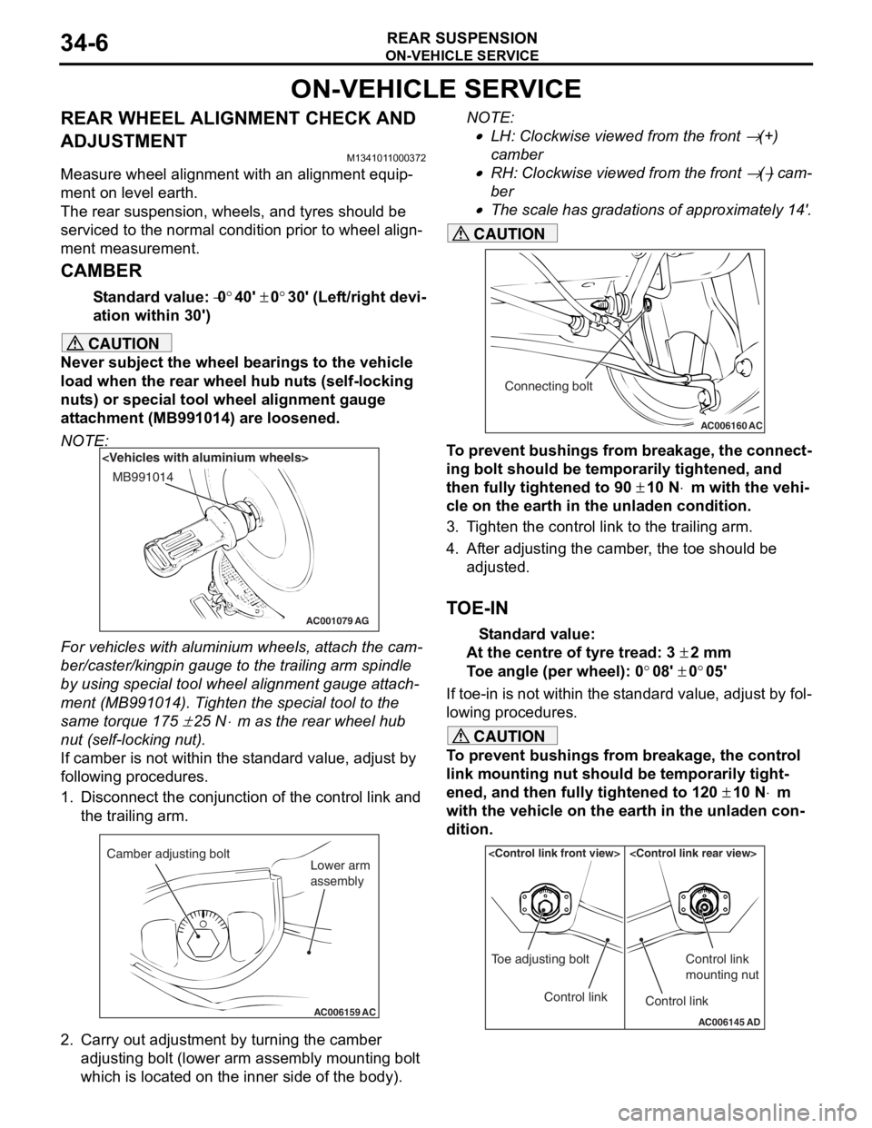
1. Disconnect the conjunction of the control link and the trailing arm.
AC006159 AC
Camber adjusting bolt
Lower arm
assembly
2. Carry out adjustment by turning the camber
adjusting bolt (lower arm assembly mounting bolt
which is located on the inner side of the body).
NOTE: .
•LH: Clockwise viewed from the front → (+)
camber
•RH: Clockwise viewed from the front → (−) cam-
ber
•
AC006160 AC
Connecting bolt
The scale has gradations of approximately 14'.
CAUTION
To prevent bushings from breakage, the connect-
ing bolt should be temporarily tightened, and
then fully tightened to 90
± 10 N⋅m with the vehi-
cle on the earth in the unladen condition.
3. Tighten the control link to the trailing arm.
4. After adjusting the camber, the toe should be
adjusted.
TOE-IN
Standard value:
At the centre of tyre tread: 3 ± 2 mm
Toe angle (per wheel): 0°08' ± 0°05'
If toe-in is not within the standard value, adjust by fol-
lowing procedures.
CAUTION
To prevent bushings from breakage, the control
link mounting nut should be temporarily tight
-
ened, and then fully tightened to 120 ± 10 N⋅m
with the vehicle on the earth in the unladen con
-
dition.
AC006145 AD
Control link
Toe adjusting boltControl link
Control link
mounting nut