Condition MITSUBISHI LANCER 2006 Owner's Manual
[x] Cancel search | Manufacturer: MITSUBISHI, Model Year: 2006, Model line: LANCER, Model: MITSUBISHI LANCER 2006Pages: 800, PDF Size: 45.03 MB
Page 206 of 800
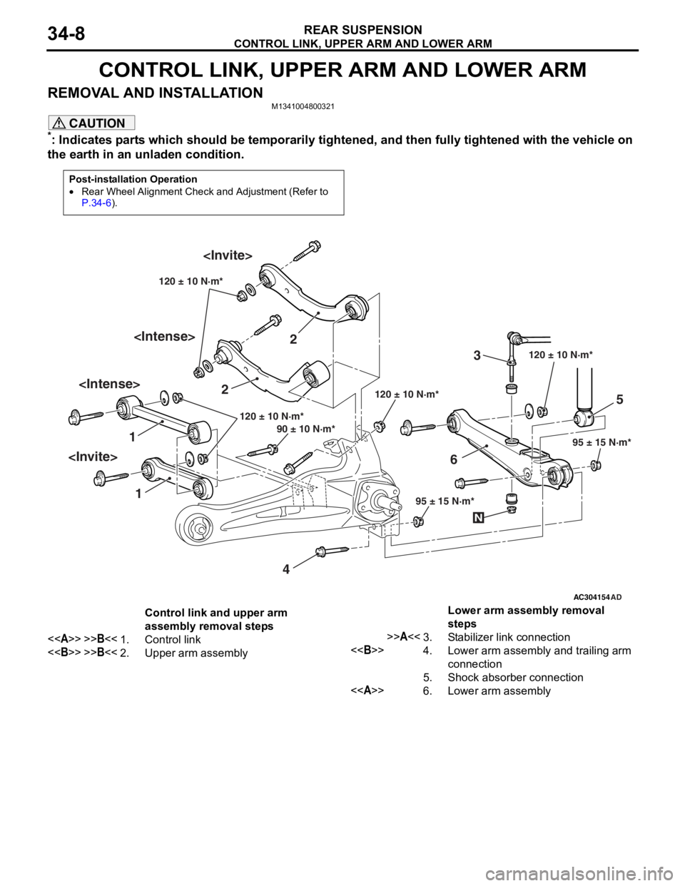
CONTROL LINK, UPPER ARM AND LOWER ARM
REAR SUSPENSION34-8
CONTROL LINK, UPPER ARM AND LOWER ARM
REMOVAL AND INSTALLATIONM1341004800321
CAUTION
*: Indicates parts which should be temporarily tightened, and then fully tightened with the vehicle on
the earth in an unladen condition.
Post-installation Operation
•Rear Wheel Alignment Check and Adjustment (Refer to
P.34-6).
AC304154
1 2
3
4 5
6
AD
120 ± 10 N·m*
95 ± 15 N·m*
120 ± 10 N·m*
120 ± 10 N·m*
95 ± 15 N·m*
90 ± 10 N·m* 120 ± 10 N·m*
N
Control link and upper arm
assembly removal steps
<>>>B<<1.Control link
<>>>B<<2.Upper arm assembly
Lower arm assembly removal
steps
>>A<<3.Stabilizer link connection
<>4.Lower arm assembly and trailing arm
connection
5.Shock absorber connection
<>6.Lower arm assembly
Page 210 of 800
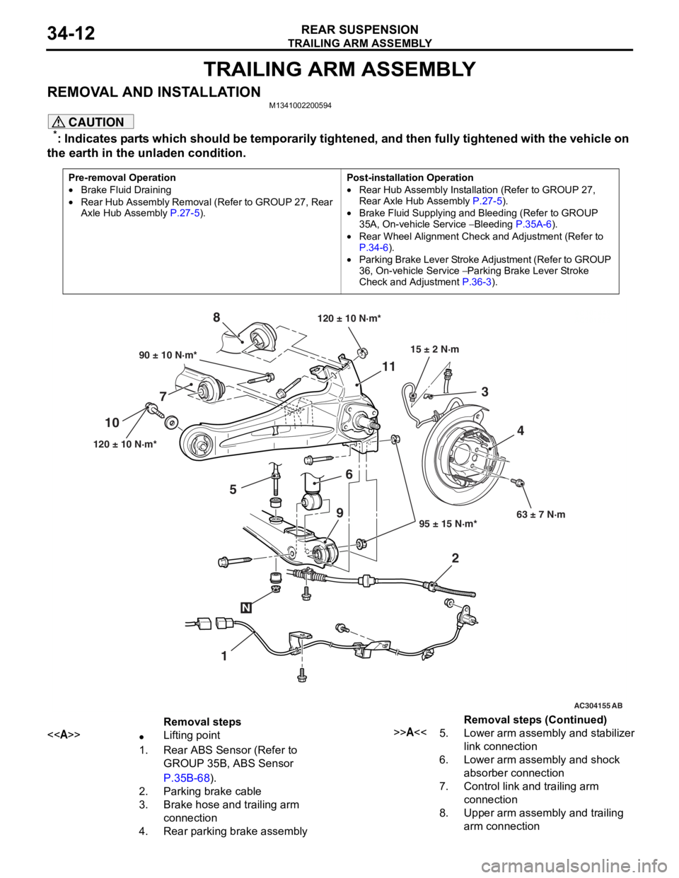
TRAILING ARM ASSEMBLY
REAR SUSPENSION34-12
TRAILING ARM ASSEMBLY
REMOVAL AND INSTALLATIONM1341002200594
CAUTION
*: Indicates parts which should be temporarily tightened, and then fully tightened with the vehicle on
the earth in the unladen condition.
Pre-removal Operation
•Brake Fluid Draining
•Rear Hub Assembly Removal (Refer to GROUP 27, Rear
Axle Hub Assembly P.27-5).
Post-installation Operation
•Rear Hub Assembly Installation (Refer to GROUP 27,
Rear Axle Hub Assembly
P.27-5).
•Brake Fluid Supplying and Bleeding (Refer to GROUP
35A, On-vehicle Service
− Bleeding P.35A-6).
•Rear Wheel Alignment Check and Adjustment (Refer to
P.34-6).
•Parking Brake Lever Stroke Ad justment (Refer to GROUP
36, On-vehicle Service
− Parking Brake Lever Stroke
Check and Adjustment
P.36-3).
AC101449
AC301223
AC304155 AB
90 ± 10 N·m*
120 ± 10 N·m* 95 ± 15 N·m*63 ± 7 N·m
6
7 8
1
10
11
23
4
120 ± 10 N·m*
15 ± 2 N·m
N
9
5
Removal steps
<>•Lifting point
1.Rear ABS Sensor (Refer to
GROUP 35B, ABS Sensor
P.35B-68).
2.Parking brake cable
3.Brake hose and trailing arm
connection
4.Rear parking brake assembly
>>A<<5.Lower arm assembly and stabilizer
link connection
6.Lower arm assembly and shock
absorber connection
7.Control link and trailing arm
connection
8.Upper arm assembly and trailing
arm connection
Removal steps (Continued)
Page 212 of 800
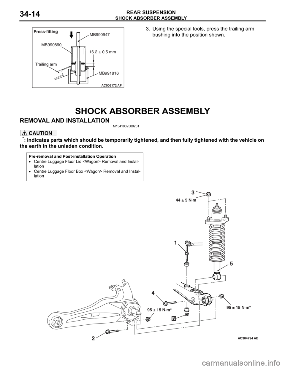
AC006172AF
Press-fitting
MB990890
Trailing arm MB990947
MB991816
16.2 ± 0.5 mm
SHOC
K ABSORBER ASSEMBL Y
REAR SUSPENSION34-14
3.Using th e sp ecial too l s, press the trailing a r m
bu s h in g in t o t h e p o s it i o n s h ow n.
SHOCK ABSORBER ASSEMBLY
REMOVA L AND INST ALLA TION
M13410025 0026 1
CAUTION
*: Indicates parts which should be temporarily tightened, and then fully tightened with the vehicle on
the earth in the unladen condition.
Pre-removal and Post-installation Operation
•Centre Luggage Floor Lid
•Centre Luggage Floor Box
AC304794AB
44 ± 5 N·m
2 41
3
5
95 ± 15 N·m* 95 ± 15 N·m*
N
Page 236 of 800

SERVICE SPECIFICATIONS
POWER STEERING37-6
SERVICE SPECIFICATIONS
M1372000300795
ItemStandard valueLimit
Steering wheel free
play mmWith engine running−30
With engine stopped10 or less−
Steering angleInner wheelInvite39°30' ± 1°30'−
Intense (LH drive vehicles)33°40' +1°00'/-2°00'−
Intense (RH drive vehicles)37°00' +1°00'/-2°00'−
Outer wheel
(reference)Invite32°30'−
Intense (LH drive vehicles)28°46'−
Intense (RH drive vehicles)30°00'−
Toe-inAt the centre of tyre tread mm1 ± 2−
Toe-angle (per wheel)0°03' ± 06'−
Tie rod end ball joint turning torque N⋅m0.5 − 2.5−
Tie rod swing resistance N [Tie rod swing torque N⋅m]8 − 27 [1.5 − 4.9]−
Stationary steering effort N [Fluctuation allowance N]29 or less [5.9 or less]−
Oil pump pressure
MPa (750
± 100 r/min.)
Oil pump relief pressure8.8 − 9.5−
Pressure under no-load conditions0.2 − 0.7−
Steering gear retention hydraulic pressure8.8 − 9.5−
Oil pressure switch operating pressure
MPaOFF → ON1.5 − 2.0−
ON → OFF0.7 − 2.0−
Steering gear total pinion torque N⋅m
[Change in torque N
⋅m]
Invite0.8 − 2.1 [0.6 or less]−
Intense0.7 − 2.1 [0.6 or less]−
Opening dimension of special tool boot band crimping tool (MB991561)
mm2.9−
Band crimped width mm2.4 − 2.8−
Page 244 of 800
ON-VEHICLE SERVICE
POWER STEERING37-14
POWER STEERING SYSTEM AIR
BLEEDING
M1372002200330
Perform air bleeding procedure as necessary after
replacing the steering gear or the steering fluid lines.
1. Raise and support the front wheels.
2. Disconnect the ignition coil connectors (Refer to GROUP 16, Ignition Coil
P.16-38 or P.16-39).
CAUTION
Perform air bleeding only while cranking the
engine. If air bleeding is performed while the
engine is running, air could enter the fluid. Dur
-
ing air bleeding, refill the steering fluid supply so
that the level never falls below the "MIN" mark on
the oil reservoir.
3. Turn the steering wheel all the way to the left and
right five or six times wh ile using the starter motor
to crank the engine intermittently several times
(for 15 to 20 seconds).
4. Connect the ignition coil connectors (Refer to GROUP 16, Ignition Coil
P.16-38 or P.16-39).
5. Start the engine (idling).
6. Turn the steering wheel to the left and right until there are no air bubbles in the oil reservoir.
7. Confirm that the fluid is not milky, and that the level is between "MAX" and "MIN" marks.
8. Confirm that there is very little change in the fluid
level when the steering wheel is turned left and
right.
CAUTION
If the fluid level rises suddenly after the engine is
stopped, the air has not been completely bled. If
air bleeding is not complete, there will be abnor
-
mal noises from the pump and the flow-control
valve, and this condition could cause reduce the
life of the power steering components.
ACX01131With engine running With engine stoppedAC
Fluid level change: Within 5 mm
9. Confirm that the change in the fluid level is no more than 5 mm when the engine is stopped and
when it is running.
10.If the change of the fluid level is 5 mm or more,
the air has not been completely bled from the
system. The air bleeding procedure must be
repeated.
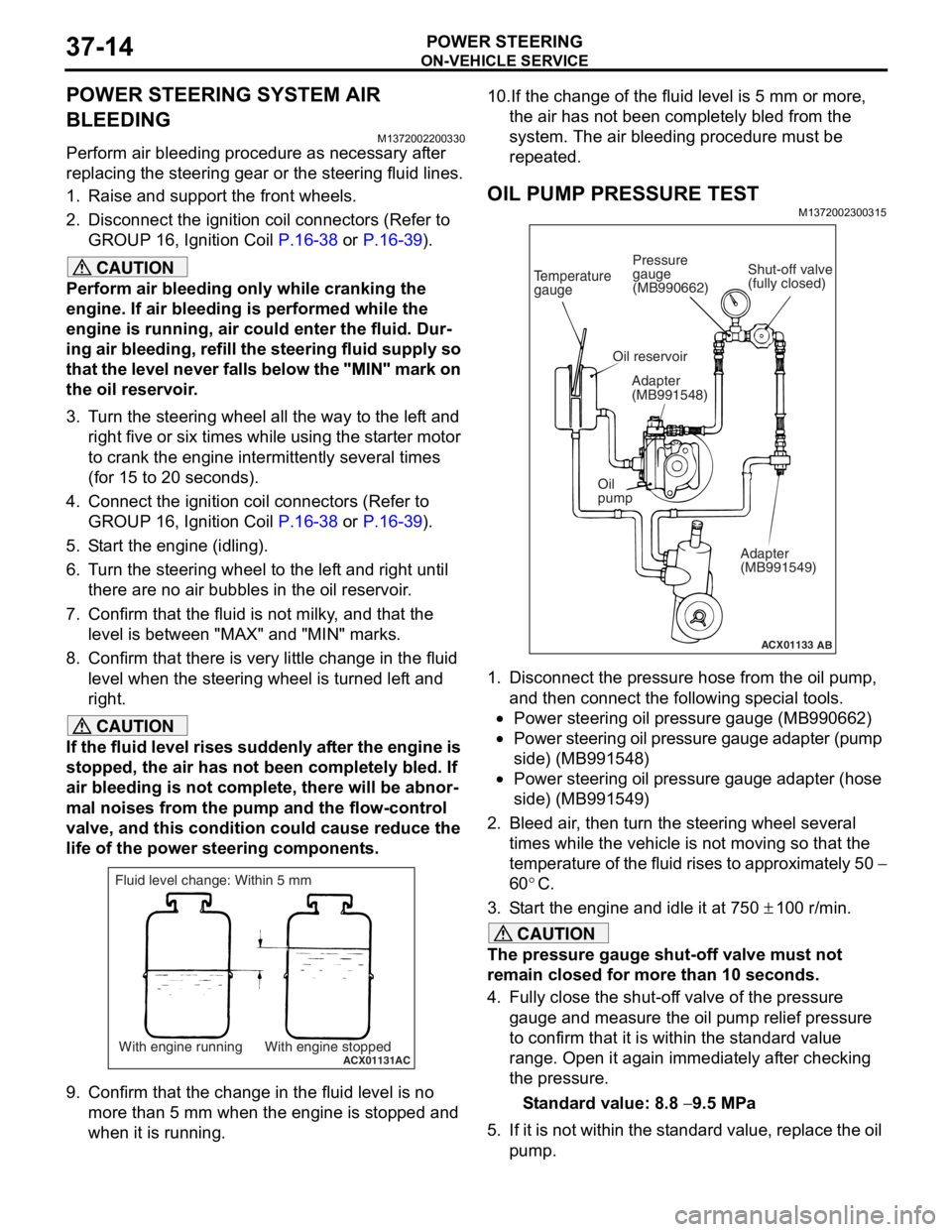
OIL PUMP PRESSURE TEST
M1372002300315
ACX01133
Temperature
gauge
Oil reservoir
Adapter
(MB991548)
Oil
pump Adapter
(MB991549)
AB
Shut-off valve
(fully closed)
Pressure
gauge
(MB990662)
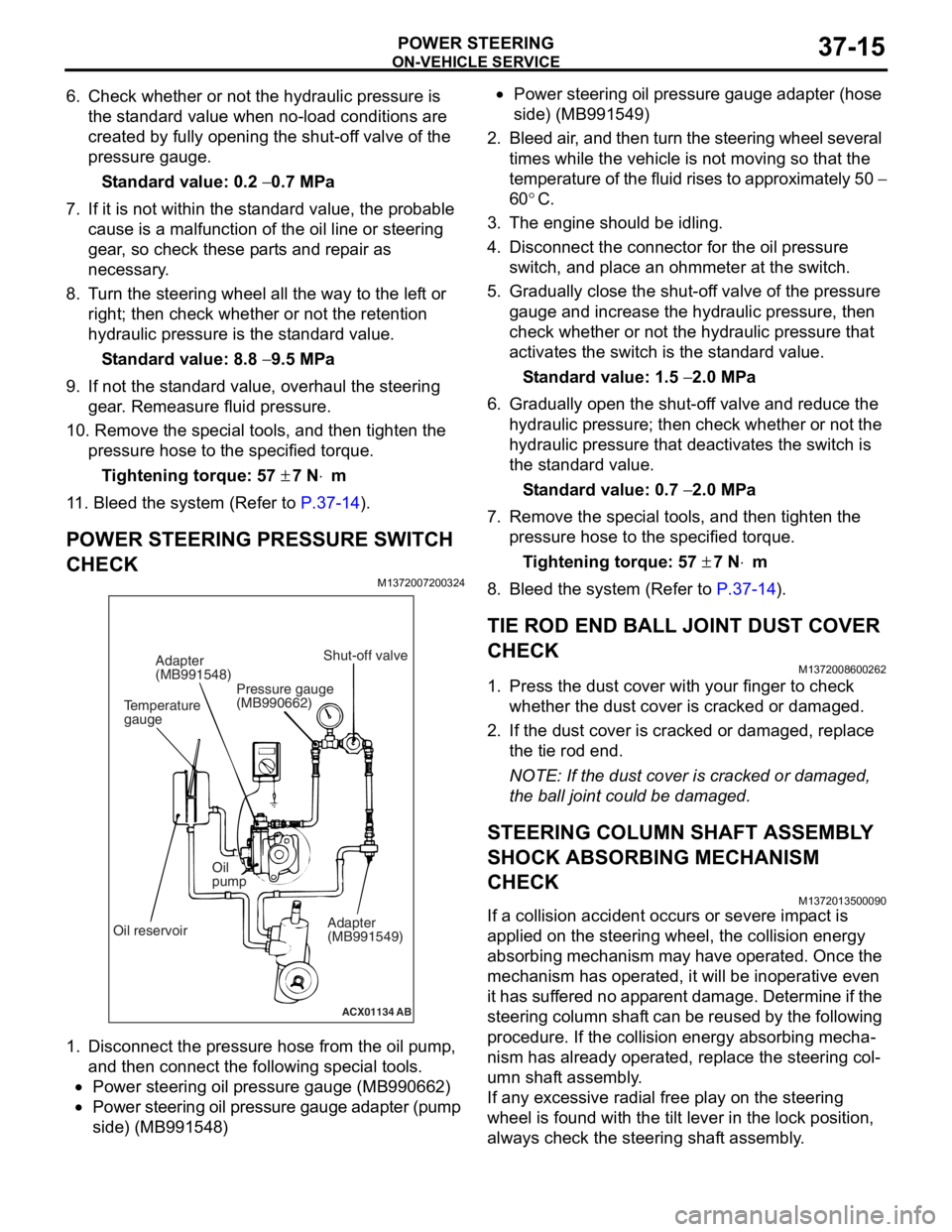
1. Disconnect the pressure hose from the oil pump,
and then connect the following special tools.
•Power steering oil pressure gauge (MB990662)
•Power steering oil pressure gauge adapter (pump
side) (MB991548)
•Power steering oil pressure gauge adapter (hose
side) (MB991549)
2. Bleed air, then turn the steering wheel several times while the vehicle is not moving so that the
temperature of the fluid rises to approximately 50
−
60
°C.
3. Start the engine and idle it at 750 ± 100 r/min.
CAUTION
The pressure gauge shut-off valve must not
remain closed for more than 10 seconds.
4. Fully close the shut-off valve of the pressure gauge and measure the oil pump relief pressure
to confirm that it is within the standard value
range. Open it again immediately after checking
the pressure.
Standard value: 8.8 − 9.5 MPa
5. If it is not within the standard value, replace the oil pump.
Page 245 of 800
ON-VEHICLE SERVICE
POWER STEERING37-15
6. Check whether or not the hydraulic pressure is the standard value when no-load conditions are
created by fully opening the shut-off valve of the
pressure gauge.
Standard value: 0.2 − 0.7 MPa
7. If it is not within the standard value, the probable cause is a malfunction of the oil line or steering
gear, so check these parts and repair as
necessary.
8. Turn the steering wheel all the way to the left or right; then check whether or not the retention
hydraulic pressure is the standard value.
Standard value: 8.8 − 9.5 MPa
9. If not the standard value, overhaul the steering gear. Remeasure fluid pressure.
10. Remove the special tools, and then tighten the
pressure hose to the specified torque.
Tightening torque: 57 ± 7 N⋅m
11. Bleed the system (Refer to P.37-14).
POWER STEERING PRESSURE SWITCH
CHECK
M1372007200324
ACX01134 AB
Temperature
gaugeAdapter
(MB991548)
Oil reservoir Oil
pump
Adapter
(MB991549)
Shut-off valve
Pressure gauge
(MB990662)
1. Disco nnect the pre s sure hose from the oil pump ,
an d then con nect the followin g sp ecial too l s.
•Power steering oil pressure gauge (MB990 662)
•Power steering oil pressure gauge ad apter (pump
side) (MB99154
8)
•Power steering oil pressure gaug e a dapte r (ho s e
side) (MB99154
9)
2. Bleed air , and the n turn t he steering wheel several
times while the vehicle is not moving so that the
tempe r atu r e o f th e flu i d rise s to approximately 50
−
60
°C.
3. Th e engine should be idling.
4.Disco nnect the conne ctor fo r the o il pr essure
switch , and p l ace an o h mmeter a t the switch .
5.Gradua lly close the shut-of f valve of the pressure
g auge a nd in crease the hyd r aulic pre ssu re, the n
check wheth e r or no t the h y drau lic pressure that
a c tivates the switch is the st a ndard valu e.
St andard va lue: 1.5 − 2.0 MPa
6.Gradua lly open the shut-of f va lve and re duce the
h y drau lic p r essure; then check whethe r o r n o t the
h y drau lic pressure that de activate s the switch is
th e st and ard va lue.
St andard va lue: 0.7 − 2.0 MPa
7.Remove the special tools, and then tighten the
p r essure hose to the specified torque .
Ti ghte n ing torque: 57 ± 7 N⋅m
8.Bleed the system (Refer to P.37-14).
TIE ROD END BALL JOINT DUST COVER
CHECK
M13720086 0026 2
1.Press th e dust co ver wit h you r fing er to check
whet her the dust cover is cra cke d or da mage d.
2.If the du st cover is cracked o r damaged, repla c e
th e tie rod end .
NOTE: If the dust cover is cra cke d or da mag ed,
th
e ball jo int could be da mage d.
STEERING COLUMN SHAFT ASSEMBL Y
SHOCK ABSORBING MECHANISM
CHECK
M13720135 0009 0
If a collision accid ent occu rs or seve re imp a ct is
applied on
the steering w heel, the collision energy
abso
r bing mechanism ma y h a ve opera t ed. Once the
mechanism
has o perate d , it will b e ino perative e v en
it has
suf f er ed no app a r en t d a mage . De termin e if the
steering colu
mn shaf t can b e reused b y th e following
proce
dure. If the collision en ergy a b sor b ing mecha
-
nism has already operated, rep l ace the steering col-
umn shaft assembly .
If any excessive radial fre e pla y on the steering
wh
eel is fo und with the tilt lever in the lock po sit i on,
always ch
eck the steering shaf t assembly .
Page 300 of 800
DOOR
BODY42-28
DOOR WINDOW GLASS ADJUSTMENT
M1423001000327
Check that the door glass moves while contacting
the door glass channel when it is raised and lowered
fully. If not, adjust the door window according to the
following procedures.
1. Remove the door trim assembly (Refer to GROUP 52A, Door trim
P.52A-17).
2. Remove the waterproof film (Refer to P.42-39).
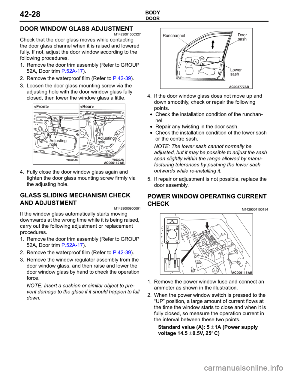
3. Loosen the door glass mounting screw via the adjusting hole with the door window glass fully
closed, then lower the window glass a little.
Y0238AUY0239AUAC006112 AB
Adjusting
holeAdjusting
hole
4.Fu lly close the doo r window g l ass aga in an d
tighten the do or gla s s moun ting scre w firmly via
th e adjusting ho le.
GLASS SLIDING MECHANISM CHECK
AND ADJUSTMENT
M14290009 0009 1
If the window glas s automatically st a r t s moving
downwards at the wron
g time while it is be ing raised ,
carry out th
e following adju s tment or re placeme n t
proce
dures.
1. Remo ve the do or trim assembly (Refer to GROUP
52 A, Door trim
P.52A-17).
2.Remove the water p roof film (Re f er to P.42-39).
3.Remove the win dow regulator a sse mbly from the
do or windo w glass, a nd the n raise and lower th e
door windo w glass b y han d t o che ck the op erat ion
fo rce.
NOTE: Insert a cushion or similar object t o pre-
vent da mage to the gla ss if it shou ld h app en t o f a ll
do
wn .
AC003777
Runchannel Door
sash
Lower
sash
AB
4. If the do or windo w g l ass do es no t move up and
d o wn smoothly , ch eck or rep a ir the followin g
po i n t s .
•Check the inst a lla tion condition of the runch a n-
nel.
•Repa ir a n y twisting in the do or sash.
•Check the inst allation condit i on of the lo we r sash
or th
e ce ntre sash.
NOTE: The lower sa sh canno t normally be
a
d
juste
d , bu t it ma y be po ssible to ad just th e sa sh
sp
an sligh t ly within the ran ge allowed b y manu
-
facturing tolerances by pu shing the lower sash
o
u twards wh ile r e -inst a lling it .
5.If rep a ir or a d justme nt is not po ssible , repla c e th e
d oor assembly .
POWER WINDOW OPERA T ING CURRENT
CHECK
M142900 1 1 0018 4
AC006115AB
1.Remove the po we r window fu se a nd co nnect an
a mme ter as sho w n in th e illustration .
2.Wh en the power win dow switch is presse d to the
“UP” position, a large amou nt of current flows at
th e time the window st a r t s to close and whe n it is
fu lly closed , so measure th e oper ation curren t in
th e int e rval between these two point s.
St andard va lue (A): 5 ± 1A (Power suppl y
volt
age
14.5
± 0 . 5V , 25°C)
Page 301 of 800
DOOR
BODY42-29
3. If the operation current is outside the standard value, refer to GROUP 54B, Troubleshooting
P.54B-15, refer to GROUP 54C, Troubleshooting
P.54C-4.
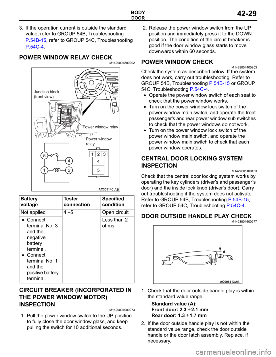
POWER WINDOW RELAY CHECKM1429001800202
AC305140
123
4
5
1 3
4
5
AB
Junction block
(front view)
Power window relayPower window
relay
Bat t ery
voltage
Teste r
co
nnectionSpecified
condition
Not applied4 − 5Ope n ci rcui t
•Connect
te
rmin al No. 3
an
d the
ne
gative
ba
ttery
te
rmin al.
•Connect
te
rmin al No. 1
an
d the
positive batt
e ry
te
rmin al.
Less than 2
ohms
CIRCUIT BREAKER (INCORPORA T ED IN
THE POW
E R W I NDOW MOT O R)
INSPECTION
M14290010 0027 3
1.Pull the p o wer windo w switch to th e UP position
to f u lly close the do or windo w g l ass, an d ke ep
pullin g the switch for 1 0 addition al secon d s.
2.Rele ase the power window switch from t he UP
position an d immediately pre ss it to t he DOW N
position. Th e con d ition of the circu i t brea ker is
goo d if t he doo r window g l ass st art s to mo ve
downward s with in 60 seconds.
POWER WI NDOW CHECKM14290044 0020 3
Check the system a s de scribed b e low . I f the system
does not work, car
r y out troublesh ootin g. Refer to
GROUP 54
B, T r ouble s hoo ting
P.54B-15 or GROUP
54C, T r oublesh ootin g P.54C-4.
•Operate the powe r wind ow switch of e a ch se at to
check that
the power window works.
•Tu rn o n the power wind ow lock switch of the
power wind
ow main swit ch, and ope rate the front
p
a ssenger's and rear power window su b switches
to check th
at the p o wer windo ws do n o t work.
•Tu rn o n the power wind ow lock switch of the
power
window main switch, and operate the
power
window main switch to check tha t each
power window
op erates.
CENTRAL DOOR LOCKING SYSTEM
INSPECTION
M142700 1 1 0013 3
Check that th e ce ntral door locking system wo rks by
op
er atin g th e key cylin de rs (d rive r ’ s an d p a sse n g e r ’ s
door) an
d the inside lock kno b (driver's door). Ca rry
out trou
bleshooting if the system does not activate.
Re
fer to GROUP 54B, T r ou bleshooting
P.54B-15,
refer to GROUP 54 C, T r o uble s hoo ting P.54C-4.
DOOR OUTSIDE HANDLE PL A Y CHECKM14230016 0027 7
AC006113
AB
A
1.Check t hat the door o u t s ide handle play is with in
th e st and ard va lue range.
St andard va lue (A):
Fron t door: 2.3 ± 2.1 m m
Rear door: 1.3 ± 1.7 mm
2. If the do or out side ha ndle play is not wit h in th e
st a ndard valu e rang e, ch eck the do or out side
h andle or the door latch assemb ly . Replace, if
ne c e ss a r y .
Page 304 of 800
DOOR
BODY42-32
INSTALLATION SERVICE POINT
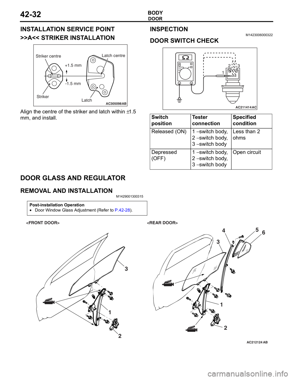
>>A<< STRIKER INSTALLATION
AC305098AB
Striker centreStriker Latch centre
Latch
+1.5 mm
-1.5 mm
Align the centre o f the striker and latch within ±1.5
mm,
and inst
all.
INSPECTION
M1423 0060 0032 2
DOOR SWITCH CHECK
AC211414
123
AC
Switch
positionTester
connectionSpecified
condition
Released (ON)1 − switch body,
2
− switch body,
3
− switch body
Less than 2
ohms
Depressed
(OFF)1 − switch body,
2
− switch body,
3
− switch body
Open circuit
DOOR GLASS AND REGULA T O R
REMOVA L AND INST ALLA TIONM14290013 0031 5
Post-installation Operation
•Door Window Glass Adjustment (Refer to P.42-28).
AC212124AB
1
23
12
3
4
5
6
Page 310 of 800
DOOR
BODY42-38
Actuator Switch Check
Lever positionTester
connectionSpecified
condition
At the "LOCK"
position1 − 2Less than 2
ohms
1 − 3Open circuit
At the "UNLOCK"
position1 − 2Open circuit
1 − 3Less than 2
ohms
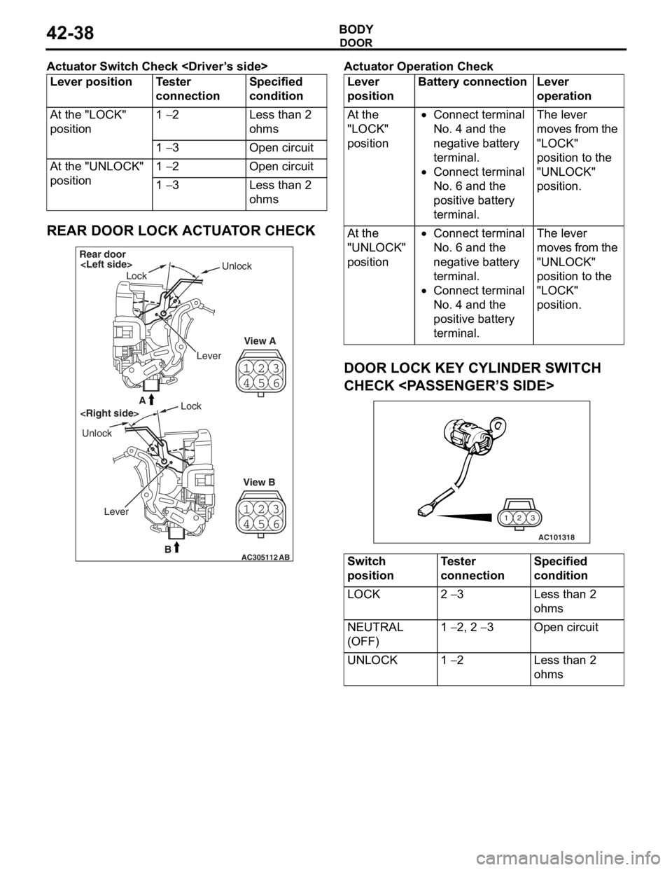
REAR DOOR LOCK ACTUATOR CHECK
23
4 1
56
23
4 1
56
AC305112B
A
AB
Rear door
Lock Unlock
View A
View B
Unlock
Lock
Lever
Ac tuator Op era t ion Check
Lever
positionBattery connectionLever
operation
At the
"LOCK"
position•Connect terminal
No. 4 and the
negative battery
terminal.
•Connect terminal
No. 6 and the
positive battery
terminal.
The lever
moves from the
"LOCK"
position to the
"UNLOCK"
position.
At the
"UNLOCK"
position•Connect terminal
No. 6 and the
negative battery
terminal.
•Connect terminal
No. 4 and the
positive battery
terminal.
The lever
moves from the
"UNLOCK"
position to the
"LOCK"
position.
DOOR LOCK KEY CYLINDER SWITCH
CHECK
AC101318
3
2
1
Switch
positionTester
connectionSpecified
condition
LOCK2 − 3Less than 2
ohms
NEUTRAL
(OFF)1 − 2, 2 − 3Open circuit
UNLOCK1 − 2Less than 2
ohms