Condition MITSUBISHI LANCER 2006 Owner's Guide
[x] Cancel search | Manufacturer: MITSUBISHI, Model Year: 2006, Model line: LANCER, Model: MITSUBISHI LANCER 2006Pages: 800, PDF Size: 45.03 MB
Page 317 of 800
TRUNK LID
BODY42-45
CAUTION
Install the trunk lid torsion bar
trunk lid torsion bar
reversed, the trunk lid torsion bar
be able to be installed because the special tool
will interfere with the trunk lid torsion bar
during installation of the trunk lid torsion bar
1. Identify the LH and RH torsion bars by the colour mark made at the centre of each torsion bar.
Trunk lid torsion barMark
colour
LHVehicles with rear spoilerGreen
Vehicles without rear spoilerWhite
green
RHVehicles with rear spoilerYe l l o w
Vehicles without rear spoilerRed
2. Insert the left end of the trunk lid torsion bar
3. Press portion A of the trunk lid torsion bar
right end against point A on the trunk lid hinge
4. Twist the portion B of the trunk lid torsion bar
moved from point B and pressed against point C
of the trunk lid hinge
Then force the portion into point D.
5. Twist the portion A of the trunk lid torsion bar
lid hinge
6. Attach the trunk lid torsion bar
trunk lid torsion bar
>>B<< TRUNK LID WEATHERSTRIP
INSTALLATION
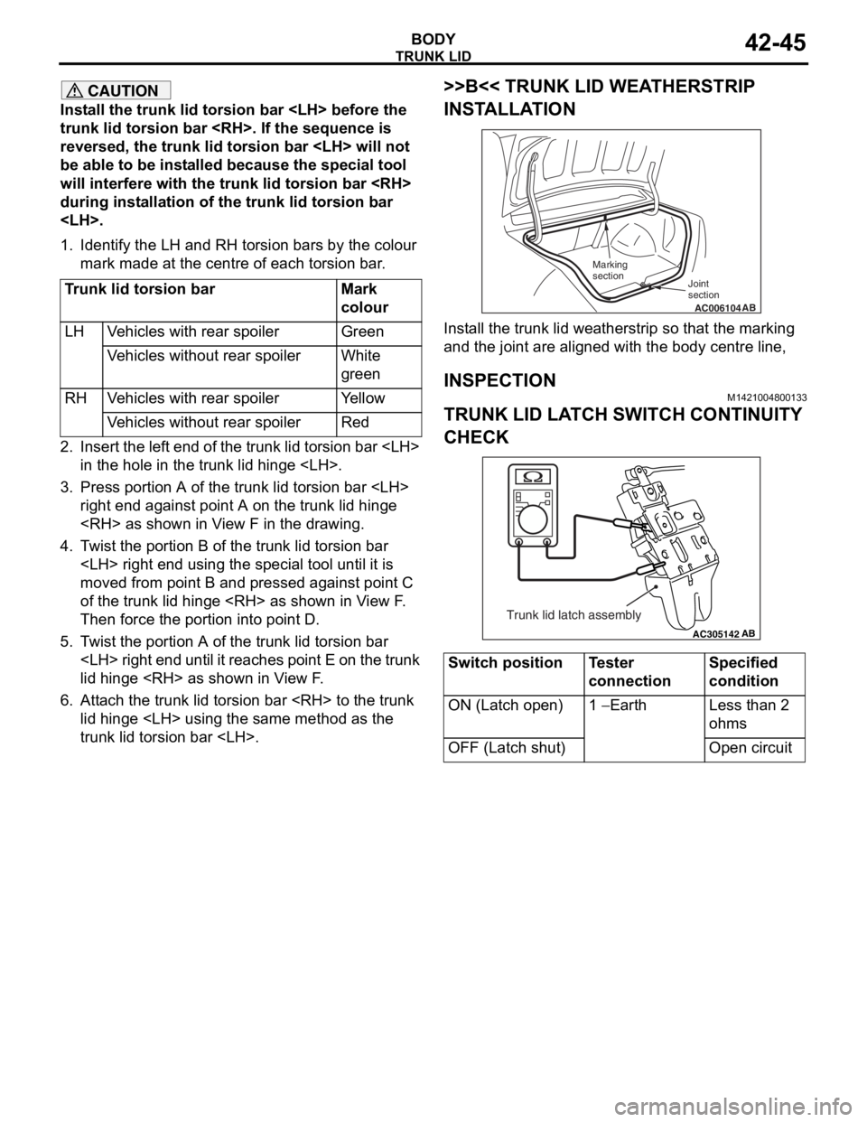
AC006104AB
Joint
section
Marking
section
Install the trunk lid weatherstrip so that the marking
and the joint are aligned with the body centre line,
INSPECTION
M1421004800133
TRUNK LID LATCH SWITCH CONTINUITY
CHECK
AC305142AB
Trunk lid latch assembly
Switch positionTester
connectionSpecified
condition
ON (Latch open)1 − Earth Less than 2
ohms
OFF (Latch shut)Open circuit
Page 323 of 800
KEYLESS ENTRY SYSTEM
BODY42-51
INSPECTION
M1424001200142
TAILGATE LOCK ACTUATOR CHECK
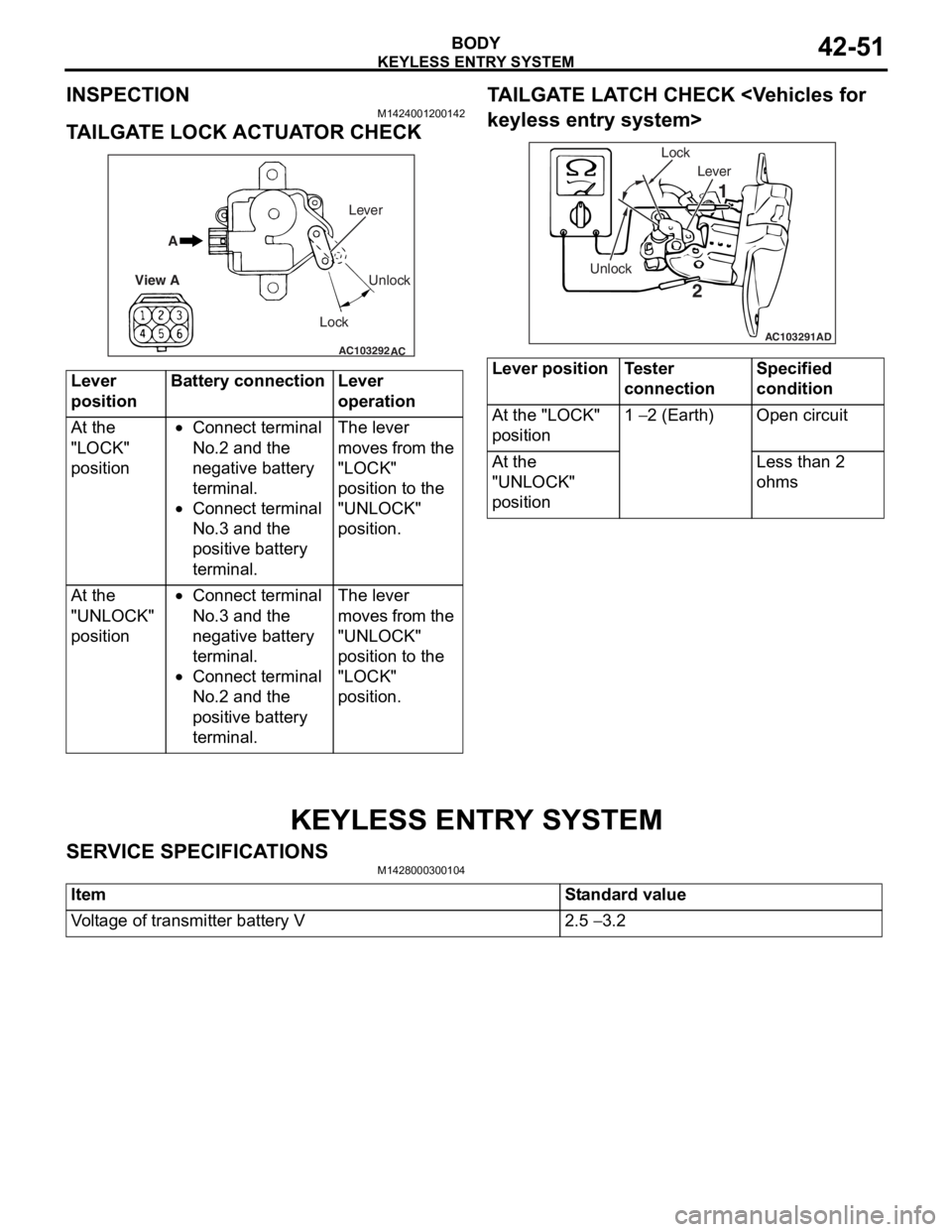
AC103292
A
View A Unlock
Lock Lever
AC
Lever
positionBatte
ry connec tionLever
o
peration
At the
"LOCK"
position•Conn ect t e rminal
No.2
and th e
ne
gative ba ttery
te
rmin al.
•Connect t e rminal
No.3
and th e
po
sit i ve battery
te
rmin al.
The le ver
moves f
r om the
"LOCK"
p
o sition t o the
"UNLOCK
"
p
o sition.
At the
"UNLOCK"
position•Conn ect t e rminal
No.3
and th e
ne
gative ba ttery
te
rmin al.
•Connect t e rminal
No.2
and th e
po
sit i ve battery
te
rmin al.
The le ver
moves f
r om the
"UNLOCK
"
p
o sition t o the
"LOCK"
p
o sition.
TA ILGA TE LA TCH CHECK
ess entry system>
AC103291
Lever
Unlock Lock
1
2
AD
Lever positionTester
connectionSpecified
condition
At the "LOCK"
position1 − 2 (Earth)Open circuit
At the
"UNLOCK"
positionLess than 2
ohms
KEYLESS ENTR Y SYSTEM
SERV ICE SPECIFICA T IONS
M14280003 0010 4
ItemStandard value
Voltage of transmitter battery V2.5 − 3.2
Page 328 of 800
KEYLESS ENTRY SYSTEM
BODY42-56
WHEN THE SPECIAL TOOL DIAGNOSIS
CODE CHECK HARNESS (MB991529) IS
USED
1. Check that the doors lock normally when the key is used.
2. Insert the ignition key.
CAUTION
Before connecting or disconnecting the earth,
turn the ignition switch to the "LOCK" (OFF)
position.
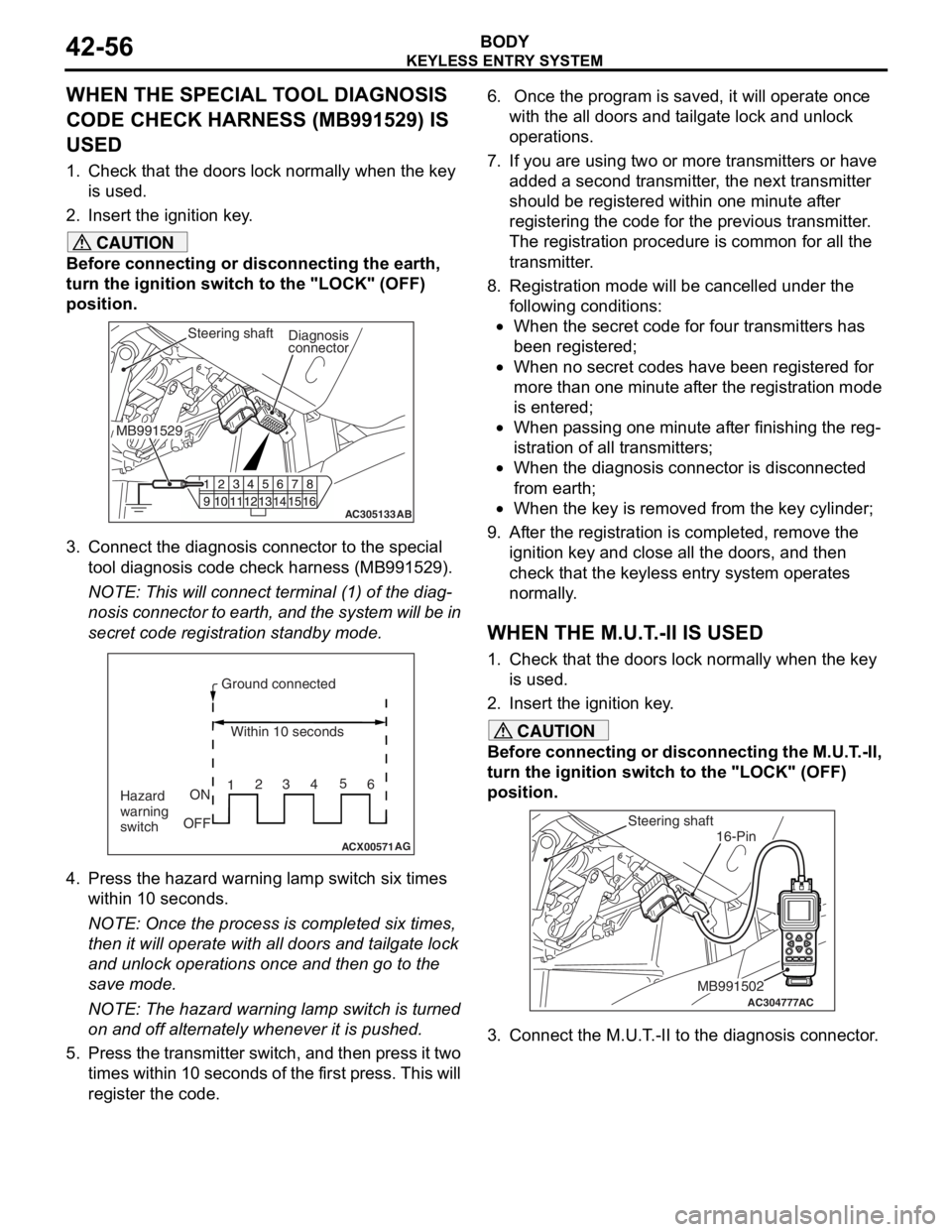
AC305133AB
Diagnosis
connector
MB991529Steering shaft
3. Connect the diagnosis connector to the special tool diagnosis code check harness (MB991529).
NOTE: This will connect terminal (1) of the diag-
nosis connector to earth, and the system will be in
secret code registration standby mode.
ACX00571
Ground connected
Within 10 seconds
Hazard
warning
switch ON
OFF 1
23
45
6
AG
4. Press the hazard warning lamp switch six times
within 10 seconds.
NOTE: Once the process is completed six times,
then it will operate with al l doors and tailgate lock
and unlock operations once and then go to the
save mode.
NOTE: The hazard warning lamp switch is turned
on and off alternately whenever it is pushed.
5. Press the transmitter switch, and then press it two times within 10 seconds of the first press. This will
register the code.
6. Once the program is saved, it will operate once
with the all doors and tailgate lock and unlock
operations.
7. If you are using two or more transmitters or have
added a second transmitter, the next transmitter
should be registered within one minute after
registering the code for the previous transmitter.
The registration procedure is common for all the
transmitter.
8. Registration mode will be cancelled under the following conditions:
•When the secret code for four transmitters has
been registered;
•When no secret codes have been registered for
more than one minute after the registration mode
is entered;
•When passing one minute after finishing the reg-
istration of all transmitters;
•When the diagnosis connector is disconnected
from earth;
•When the key is removed from the key cylinder;
9. After the registration is completed, remove the ignition key and close all the doors, and then
check that the keyless entry system operates
normally.
WHEN THE M.U.T.-II IS USED
1. Check that the doors lock normally when the key
is used.
2. Insert the ignition key.
CAUTION
Before connecting or disconnecting the M.U.T.-II,
turn the ignition switch to the "LOCK" (OFF)
position.
AC304777
Steering shaft
ACMB991502
16-Pin
3. Connect the M.U.T.-II to the diagnosis connector.
Page 330 of 800
KEYLESS ENTRY SYSTEM
BODY42-58
7. If you are using two or more transmitters or have added a second transmitter, the next transmitter
should be registered within one minute after
registering the code for the previous transmitter.
The registration procedure is common for all the
transmitter.
8. Registration mode will be cancelled under the following conditions:
•When the secret code for four transmitters has
been registered;
•When no secret codes have been registered for
more than one minute after the registration mode
is entered;
•When passing one minute after finishing the reg-
istration of all transmitters;
•When the V.C.I. is disconnected from the diagno-
sis connector;
•When the key is removed from the key cylinder;
9. After the registration is completed, remove the ignition key and close all the doors, and then
check that the keyless entry system operates
normally.
TRANSMITTER
DISASSEMBLY AND REASSEMBLY
M1428002800172
Post-reassembly operation
•Transmitter operation check
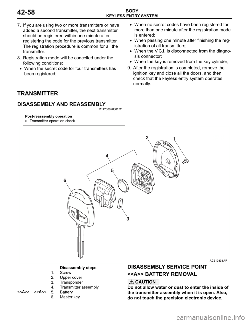
AC310838AC303199
AC3041181
2
AF
5
3
4
6
Disassembly steps
1.Screw
2.Upper cover
3.Transponder
4.Transmitter assembly
<>>>A<<5.Battery
6.Master key
DISASSEMBL Y SER V ICE POINT
<> BATTER Y REMOV A L
CAUTION
Do not allow water or dust to enter the inside of
the transmitter assembly when it is open. Also,
do not touch the precision electronic device.
Page 360 of 800

WINDSHIELD WIPER AND WASHER
EXTERIOR51-28
WINDSHIELD WIPER AND WASHER
GENERAL INFORMATIONM1511000100514
WINDSHIELD WIPER AND WASHER
OPERATION
Windshield Low-speed (and High-speed)
Wiper Operation
•If the windshield low-speed wiper switch is turned
to the ON position with the ignition switch at the
"ACC" or "ON" position, the column switch sends
a low-speed wiper ON and high-speed wiper OFF
signals to the front-ECU. This turns the wiper sig
-
nal on and the wiper speed control relay off
(low-speed), causing the wipers to operate at
low-speed.
•If the windshield high-speed wiper switch is
turned to the ON position, the column switch
sends a low-speed wiper OFF and high-speed
wiper ON signals to the front-ECU. This turns
both the wiper signal and the wiper speed control
relay on (high-speed), causing the wipers to
operate at high-speed.
NOTE: The windshield wiper speed is switchable
with the built-in wiper speed control relay.
High-speed operations take place when the wiper
speed control relay is set to "ON" and low-speed
operations take place when the wiper speed control
relay is set to "OFF".
Windshield Intermittent Wiper Operation
The ETACS-ECU calculates the wiper operation
interval according to the voltage signal sent from the
column switch. Then the ETACS-ECU sends a signal
to the front-ECU. The front-ECU determines the
wiper operation interval and turns on the wiper relay
signal relay. This causes the wiper auto stop relay to
turn on. Then the wiper auto stop relay will turn off
after the wipers reach the park position. This causes
the wiper signal relay and then the wipers to turn off.
If the wiper signal relay remains off for the wiper
operation interval, the relay turns on again, causing
the wipers to operate in intermittent mode.
Windshield Mist Wiper Operation
•If the windshield mist wipe r switch is turned to the
ON position with the ignition switch at the "ACC"
or "ON" position, the mist wiper high-speed oper
-
ation signal is sent to the front-ECU. This signal
turns on the wiper speed control relay, causing
the wipers to work at high-speed while the mist
switch is on.
•While the windshield mist wiper switch remains
turned on when the intermittent mode is still work
-
ing, the wipers work as the mist wiper. However,
the wipers return to the intermittent mode again
when the switch is changed back to "INT" posi
-
tion.
•To prevent the windshield mist wiper from operat-
ing when the windshield wiper switch is turned
OFF, the windshield mist wiper does not work for
0.5 second after the windshi eld intermittent wiper
switch, the windshield low-speed wiper switch
and the windshield high-speed wiper switch are
turned OFF.
Windshield Washer Operation
•If the windshield washer switch is turned to ON
position with the ignition sw itch at "ACC" or "ON"
position, the windshield wa sher ON signal is sent
to the front-ECU. After 0.3 second, the windshield
wiper signal turns on. After the windshield washer
switch signal turns off, the windshield wiper signal
turns off in three seconds.
•If the windshield washer switch is turned on while
the windshield wiper is at intermittent mode,
when the windshield washer switch is turned OFF
within 0.2 second, the wiper works only once to
perform mist operation by the windshield washer
switch. When the ON condi tion of the windshield
washer switch continues more than 0.2 second,
the wiper performs the same movement as nor
-
mal condition from the time when 0.2 second has
elapsed and then returns to the intermittent
motion.
SERVICE SPECIFICATION
M1511000300325
ItemStandard value
Windshield wiper blade park position mm34 ± 5
Page 366 of 800
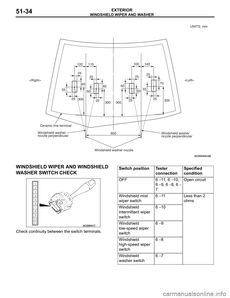
AC304420
305
70
25
55 140
100
120 115
305 300
600
3002525
25
25
25
25
25
55
6560
50
60
50
AB
Windshield washer
nozzle perpendicular
Windshield washer
nozzle perpendicular
Windshield washer nozzle
Ceramic line terminal
UNITS: mm
WINDSHIELD WI PER AND W A SHER
EXTERIOR51-34
WI NDSHIELD W I PER AND WINDSHIELD
W
A SHER SWIT CH CHECK
1
6
8
11 10 9 7
5 4
3
2
AC000417
Che
c k cont inuity be tween th e switch ter m in als.
Switch positionTester
connectionSpecified
condition
OFF6 − 11 , 6 − 10,
6 − 9, 6 − 8, 6 −
7
Open circuit
Windshield mist
wiper switch6 − 11Less than 2
ohms
Windshield
intermittent wiper
switch6 − 10
Windshield
low-speed wiper
switch6 − 9
Windshield
high-speed wiper
switch6 − 8
Windshield
washer switch6 − 7
Page 370 of 800

REAR WIPER AND WASHER
EXTERIOR51-38
2. Disconnect the battery cable from the rear windshield wiper motor while it is turning and then
check to see that the motor stops.
3. Re-connect the battery as shown in Figure (B).
4. Check to see that the rear windshield wiper motor runs and then stops at the automatic stop
position.
REAR WASHER MOTOR CHECK
1
2
AC005900
1.Remo ve th e rear washer t ank assembly with th e
wash er hose att a ched. T hen fill t he wash er t ank
with wa ter .
2.Check to see t hat t he wate r is vigor ously spra yed
when conn ecting the positive batt e ry te rmin al to
termina l number 2 and te rmin al nu mber 1 to th e
neg ative batt e ry te rmin al.
REAR WA SHER FLUI D EJECTION CHECK
CAUTION
Take care not to damage the nozzle when insert-
ing the flat-tipped screwdriver into it.
AC304544AC
Unit: mm
57 84 125
6
Section A – A
A
A
High-mounted
stop lamp Rear washer nozzle
Flat-tipped screwdriverCeramic line terminal
Washer nozzle
perpendicular
For the vertical aiming of washer nozzle, insert the
flat-tipped screwdriver into the nozzle and move it to
the arrow direction.
REAR WIPER AND WASHER SWITCH
CHECK
1
6
8
11 10 9 7
5 4
3
2
AC000417
Check continuity between the switch terminals.
Switch positionTester
connectionSpecified
condition
OFF4 − 6, 5 − 6Open circuit
Rear wiper switch4 − 6Less than 2
ohms
Rear washer
switch5 − 6
Page 378 of 800
DOOR MIRROR
EXTERIOR51-46
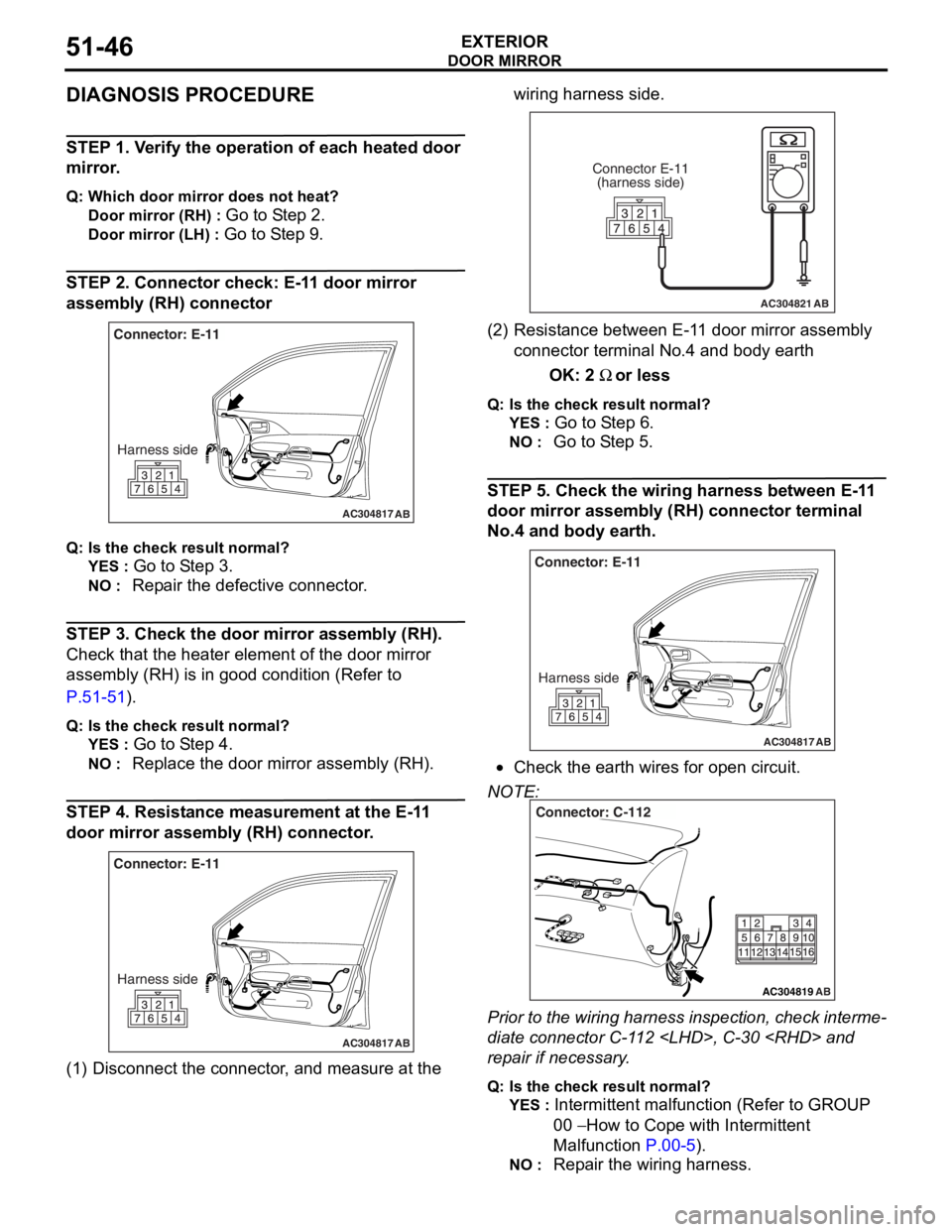
DIAGNOSIS PROCEDURE
STEP 1. Verify the operation of each heated door
mirror.
Q: Which door mirror does not heat?
Door mirror (RH) : Go to Step 2.
Door mirror (LH) : Go to Step 9.
STEP 2. Connector check: E-11 door mirror
assembly (RH) connector
AC304817
Connector: E-11Harness side
AB
Q : Is the check result normal?
YES : Go to S t ep 3.
NO : Repa ir the defective connector .
STEP 3. Ch eck the door mirror assem bly (RH).
Chec k that th e heat er ele m ent of the door mirror
assembly (RH) is in
good condition (Refer to
P.5 1 -51).
Q: Is the check result normal?
YES : Go to S t ep 4.
NO : Replac e th e door mirro r assemb ly ( R H).
STEP 4. Re sist an ce mea surement at the E-1 1
door mirror
assem bly (RH) connec tor .
AC304817
Connector: E-11
Harness side
AB
(1) D isconn ect t he co nnector , an d me asure at the wiring harn e ss side.
AC304821
Connector E-11
(harness side)
AB
(2) R esist ance bet we en E-1 1 door mirro r assemb ly
connector termina l No.4 a nd bod y ea rth
OK: 2 Ω or less
Q:Is t h e che c k r esu lt n o rmal?
YES : Go to S t ep 6 .
NO : Go to S t ep 5.
STEP 5 . Check the wiring harness b e twee n E-1 1
door mirror assem
bly (RH) conne ctor terminal
No.
4 and bo dy earth.
AC304817
Connector: E-11
Harness side
AB
•Check th e earth wires f o r open circuit.
NOTE:
AC304819
Connector: C-112
AB
Prior to the wiring harness insp ection, check interme-
diate connector C-1 1 2
rep
a ir if necessary .
Q:Is t h e che c k r esu lt n o rmal?
YES : Intermittent malfun ctio n (Refer to GROUP
00
− Ho w to Cope wit h Intermitte nt
Ma
lfunction
P.00-5).
NO : Repa ir th e wirin g harne ss.
Page 384 of 800
DOOR MIRROR
EXTERIOR51-52
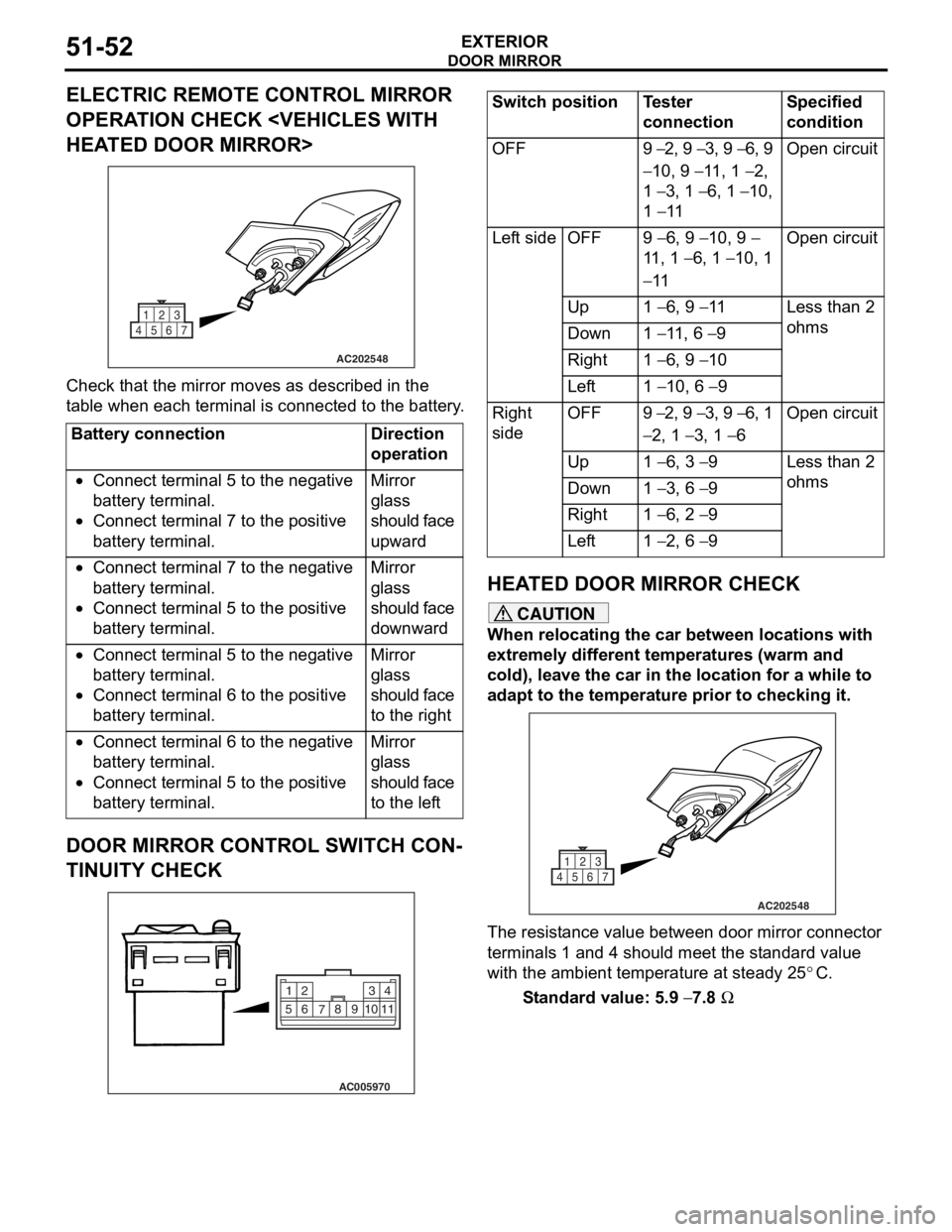
ELECTRIC REMOTE CONTROL MIRROR
OPERATION CHECK
AC202548
1
4567 23
Che
c k that th e mirror moves as describe d in the
t
a b l e when each terminal is conn ecte d to the batter y .
Battery connectionDirection
operation
•Connect terminal 5 to the negative
battery terminal.
•Connect terminal 7 to the positive
battery terminal.
Mirror
glass
should face
upward
•Connect terminal 7 to the negative
battery terminal.
•Connect terminal 5 to the positive
battery terminal.
Mirror
glass
should face
downward
•Connect terminal 5 to the negative
battery terminal.
•Connect terminal 6 to the positive
battery terminal.
Mirror
glass
should face
to the right
•Connect terminal 6 to the negative
battery terminal.
•Connect terminal 5 to the positive
battery terminal.
Mirror
glass
should face
to the left
DOOR MIRROR CONTROL SWITCH CON-
TINUITY CHECK
AC005970
2
14
3
510 9
8
7
6
11
Switch positionTester
connectionSpecified
condition
OFF9 − 2, 9 − 3, 9 − 6, 9
− 10, 9 − 11, 1 − 2,
1
− 3, 1 − 6, 1 − 10,
1
− 11
Open circuit
Left sideOFF9 − 6, 9 − 10, 9 −
11 , 1
− 6, 1 − 10, 1
− 11
Open circuit
Up1 − 6, 9 − 11Less than 2
ohms
Down1 − 11, 6 − 9
Right1 − 6, 9 − 10
Left1 − 10, 6 − 9
Right
sideOFF9 − 2, 9 − 3, 9 − 6, 1
− 2, 1 − 3, 1 − 6
Open circuit
Up1 − 6, 3 − 9Less than 2
ohms
Down1 − 3, 6 − 9
Right1 − 6, 2 − 9
Left1 − 2, 6 − 9
HEA T ED DOOR MIRROR CHECK
CAUTION
When relocating the car between locations with
extremely different temperatures (warm and
cold), leave the car in the location for a while to
adapt to the temperature prior to checking it.
AC202548
1
4567 23
The resistance value between door mirror connector
terminals 1 and 4 should meet the standard value
with the ambient temperature at steady 25
°C.
Standard value: 5.9 − 7.8 Ω
Page 389 of 800
55-1
GROUP 55
HEATER, AIR
CONDITIONER AND
VENTIL ATION
CONTENTS
HEATER, AIR CONDITIONER AND VE NTILATION . . . . . . . . .55A
AUTOMATIC AIR CONDITIONER . . . . . . . . . . . . . . . . . . . . . . .55B