Transmission MITSUBISHI LANCER 2006 User Guide
[x] Cancel search | Manufacturer: MITSUBISHI, Model Year: 2006, Model line: LANCER, Model: MITSUBISHI LANCER 2006Pages: 800, PDF Size: 45.03 MB
Page 172 of 800
GENERAL INFORMATION
POWER PLANT MOUNT32-2
GENERAL INFORMATION
M1321000100340
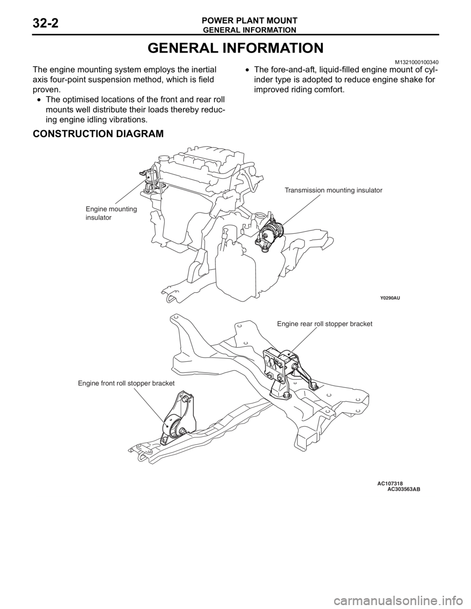
The engine mounting system employs the inertial
axis four-point suspension method, which is field
proven.
•The optimised locations of the front and rear roll
mounts well distribute their loads thereby reduc
-
ing engine idling vibrations.
•The fore-and-aft, liquid-filled engine mount of cyl-
inder type is adopted to reduce engine shake for
improved riding comfort.
CONSTRUCTION DIAGRAM
AC107318
Y0290AU
AC303563
Engine mounting
insulatorTransmission mounting insulator
Engine rear roll stopper bracket
Engine front roll stopper bracket
AB
Page 174 of 800
ENGINE MOUNTING
POWER PLANT MOUNT32-4
ENGINE MOUNTING
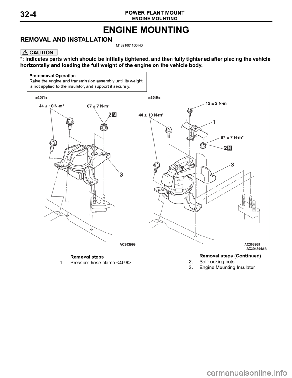
REMOVAL AND INSTALLATIONM1321001100440
CAUTION
*: Indicates parts which should be initially tightened, and then fully tightened after placing the vehicle
horizontally and loading the full weight of the engine on the vehicle body.
Pre-removal Operation
Raise the engine and transmission assembly until its weight
is not applied to the insulator, and support it securely.
AC303999AC303968AC304304AB
<4G1> <4G6>
44 ± 10 N·m* 67 ± 7 N·m*
2N
3
44 ± 10 N·m*
67 ± 7 N·m*
2N
3
12 ± 2 N·m
1
Removal steps
1.Pressure hose clamp <4G6>2.Self-locking nuts
3.Engine Mounting Insulator
Removal steps (Continued)
Page 175 of 800
TRANSMISSION MOUNTING
POWER PLANT MOUNT32-5
TRANSMISSION MOUNTING
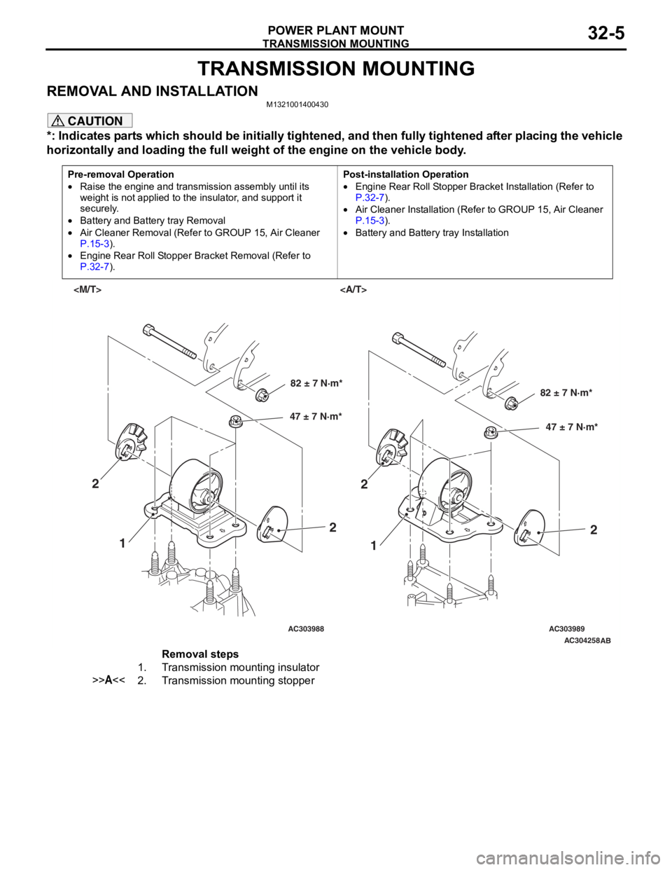
REMOVAL AND INSTALLATIONM1321001400430
CAUTION
*: Indicates parts which should be initially tightened, and then fully tightened after placing the vehicle
horizontally and loading the full weight of the engine on the vehicle body.
Pre-removal Operation
•Raise the engine and transmission assembly until its
weight is not applied to the insulator, and support it
securely.
•Battery and Battery tray Removal
•Air Cleaner Removal (Refer to GROUP 15, Air Cleaner
P.15-3).
•Engine Rear Roll Stopper Bracket Removal (Refer to
P.32-7).
Post-installation Operation
•Engine Rear Roll Stopper Bracket Installation (Refer to
P.32-7).
•Air Cleaner Installation (Refer to GROUP 15, Air Cleaner
P.15-3).
•Battery and Battery tray Installation
AC303988AC303989AC304258
AB
82 ± 7 N·m*
47 ± 7 N·m*82 ± 7 N·m*
47 ± 7 N·m*
1 1
2
22
2
Removal steps
1.Transmission mounting insulator
>>A<<2.Transmission mounting stopper
Page 176 of 800
TRANSMISSION MOUNTING
POWER PLANT MOUNT32-6
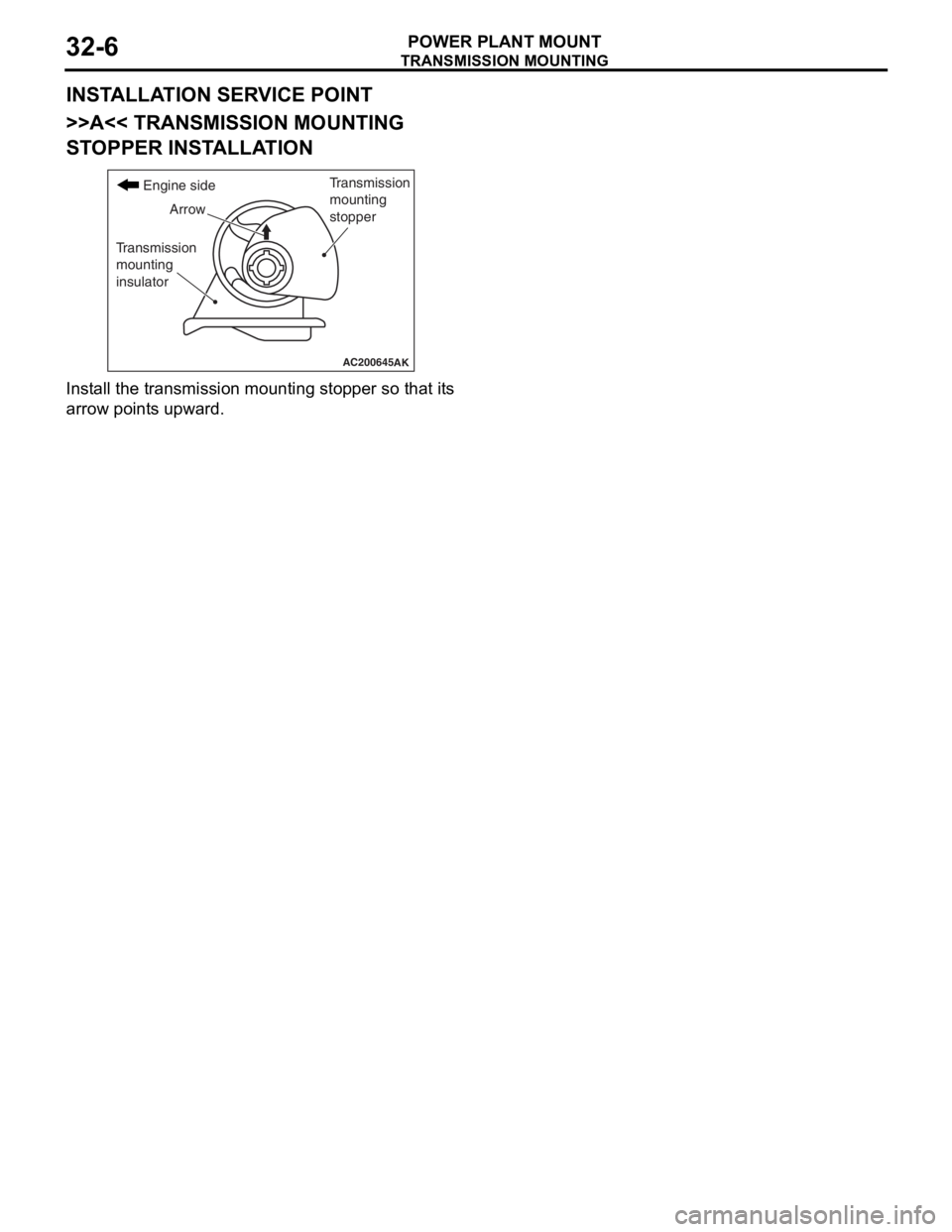
INSTALLATION SERVICE POINT
>>A<< TRANSMISSION MOUNTING
STOPPER INSTALLATION
AC200645
Transmission
mounting
stopper
Arrow
Transmission
mounting
insulator
Engine side
AK
Install the t r ansmissio n mo untin g sto pper so that it s
arrow point
s upward .
Page 177 of 800
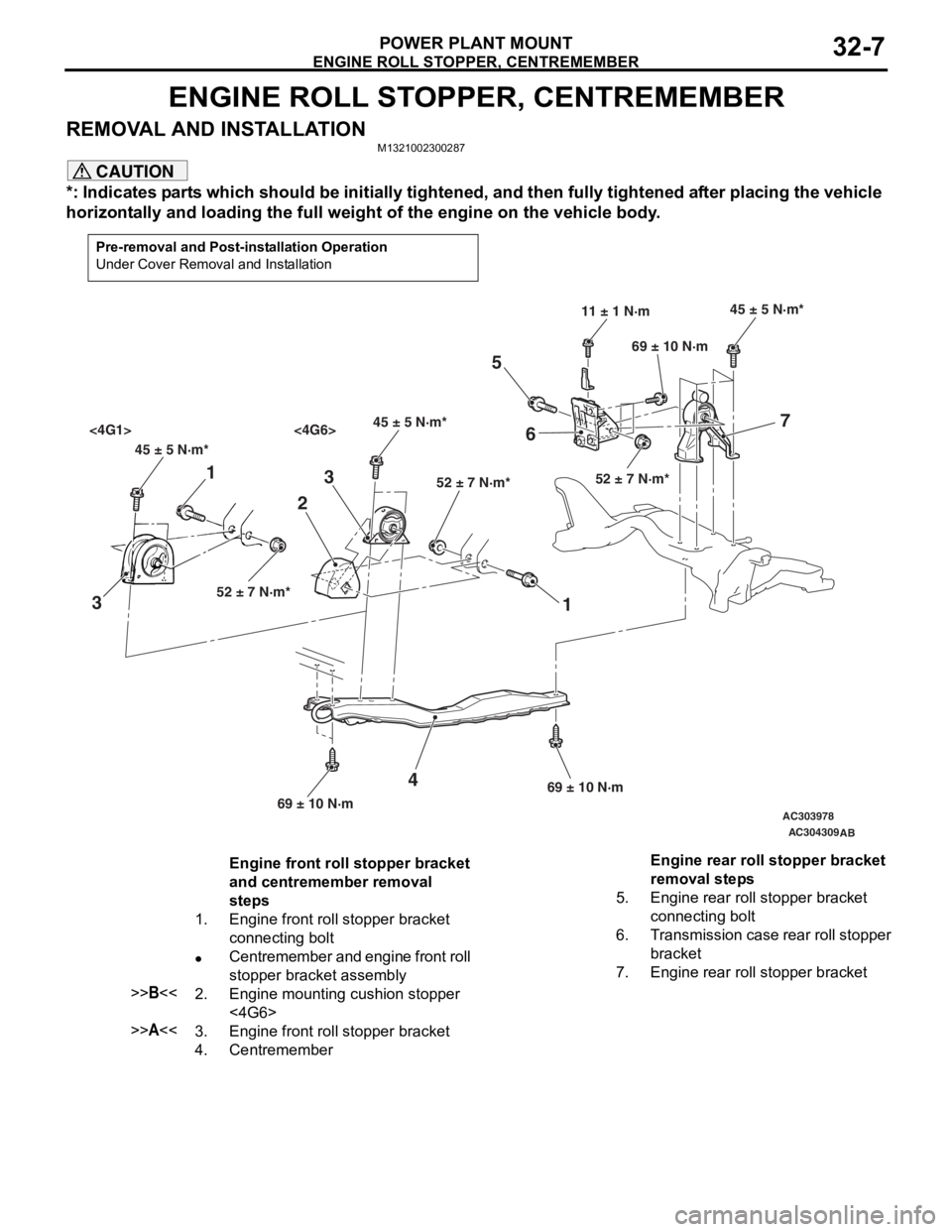
ENGINE ROLL STOPPER, CENTREMEMBER
POWER PLANT MOUNT32-7
ENGINE ROLL STOPPER, CENTREMEMBER
REMOVAL AND INSTALLATIONM1321002300287
CAUTION
*: Indicates parts which should be initially tightened, and then fully tightened after placing the vehicle
horizontally and loading the full weight of the engine on the vehicle body.
Pre-removal and Post-installation Operation
Under Cover Removal and Installation
AC303978
AC304309
45 ± 5 N·m*45 ± 5 N·m*
<4G1> <4G6>
52 ± 7 N·m* 52 ± 7 N·m*
45 ± 5 N·m*
52 ± 7 N·m*
11 ± 1 N·m
69 ± 10 N·m
69 ± 10 N·m 69 ± 10 N·m
1
3 2
1
3
4
56 7
AB
Engine front roll stopper bracket
and centremember removal
steps
1.Engine front roll stopper bracket
connecting bolt
•Centremember and engine front roll
stopper bracket assembly
>>B<<2.Engine mounting cushion stopper
<4G6>
>>A<<3.Engine front roll stopper bracket
4.Centremember
Engine rear roll stopper bracket
removal steps
5.Engine rear roll stopper bracket
connecting bolt
6.Transmission case rear roll stopper
bracket
7.Engine rear roll stopper bracket
Page 181 of 800
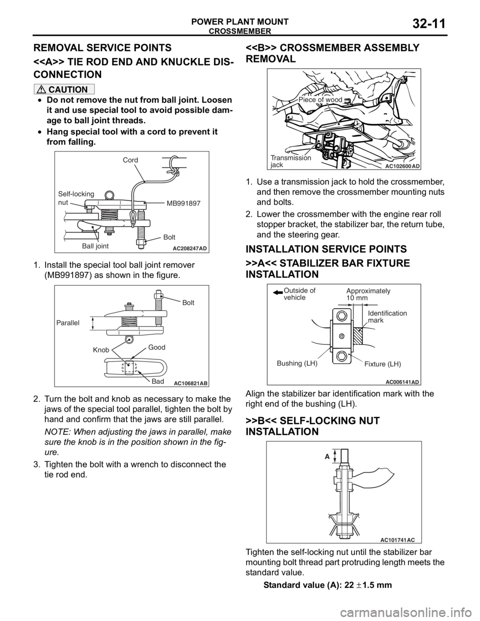
Page 193 of 800
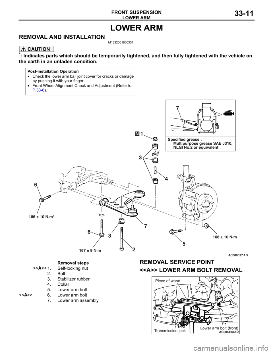
LOWER ARM
FRONT SUSPENSION33-11
LOWER ARM
REMOVAL AND INSTALLATIONM1332001600331
CAUTION
*: Indicates parts which should be temporarily tightened, and then fully tightened with the vehicle on
the earth in an unladen condition.
Post-installation Operation
•Check the lower arm ball join t cover for cracks or damage
by pushing it with your finger.
•Front Wheel Alignment Check and Adjustment (Refer to
P.33-6).
AC006097 AD
7
1
3 4
5
108 ± 10 N·m
186 ± 10 N·m*
7
3
6
N
Specified grease :
Multipurpose grease SAE J310,
NLGI No.2 or equivalent
167 ± 9 N·m
6
2
Removal steps
>>A<<1.Self-locking nut
2.Bolt
3.Stabilizer rubber
4.Collar
5.Lower arm bolt
<>6.Lower arm bolt
7.Lower arm assembly
REMOVAL SERVICE POINT
<> LOWER ARM BOLT REMOVAL
AC006133
ADLower arm bolt (front)Transmission jackPiece of wood
Page 194 of 800
LOWER ARM
FRONT SUSPENSION33-12
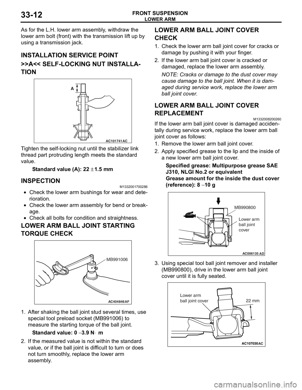
As for the L.H. lower arm assembly, withdraw the
lower arm bolt (front) with the transmission lift up by
using a transmission jack.
INSTALLATION SERVICE POINT
>>A<< SELF-LOCKING NUT INSTALLA-
TION
AC101741AC
A
T i ghten the self-locking nut un til t he st abilizer link
thread p
a rt protrud i ng length meet s the st a ndard
valu
e.
St andard va lue (A): 22 ± 1.5 m m
INSPECTION
M1332 0017 0028 6
•Check the lower arm bushing s for wear and det e-
riora t i o n.
•Check th e lo we r arm assemb ly for be nd or break-
age.
•Check all bo lt s for c ond ition and straightness.
LOWER ARM BALL JOINT ST ARTING
T
O RQUE CHECK
AC404846AF
MB991006
1.Af ter shaking the b a ll joint stud several times, use
special tool p r eloa d socke t (MB991 006) to
measure the st artin g torqu e of the ball joint.
St andard va lue: 0 − 3.9 N⋅m
2.If the measu r ed value is n o t within the st anda rd
value , or if the ba ll joint is dif f icu l t to t u rn or d oes
no t turn smo o thly , replace the lower a r m
asse mbly .
LOWER ARM BALL JOINT COVER
CHECK
1.Check t he lo we r arm b a ll joint co ver fo r cracks or
d a mag e by push i ng it with your finger .
2.If the lower arm ball joint co ver is cracked or
d a mag ed, rep l ace the lower arm assemb ly .
NOTE: Cracks or dama ge to t he dust co ver may
cause damage to the b a ll join t. When it is dam
-
aged du ring service wo rk, rep l ace the lower arm
b
a ll j o in t cover .
LOWER ARM BALL JOINT COVER
REPLACEMENT
M13320082 0026 0
If the lower arm ball jo int cove r is dama ged acciden-
ta lly durin g ser v ice work, repla c e th e lower arm b a ll
join
t cover as follows:
1.Remove the lower arm ball joint cover .
2.App l y specified grea se to the lip an d the inside of
a new lower arm ba ll join t cover .
Specified grease: Multipurpos e grease SAE
J310,
NLGI No.2 o r e quivale n t
Grease amount for the insi de the du st cove r
(re
f erence): 8
− 10 g
AC006135AD
MB990800
Lower arm
ball joint
cover
3. Using special tool ball joint remover and inst aller
(MB99080 0), drive in the lower arm ball jo int
cove r until it is fu lly se ated.
AC107030AC
22 mm
Lower arm
ball joint cover
Page 197 of 800
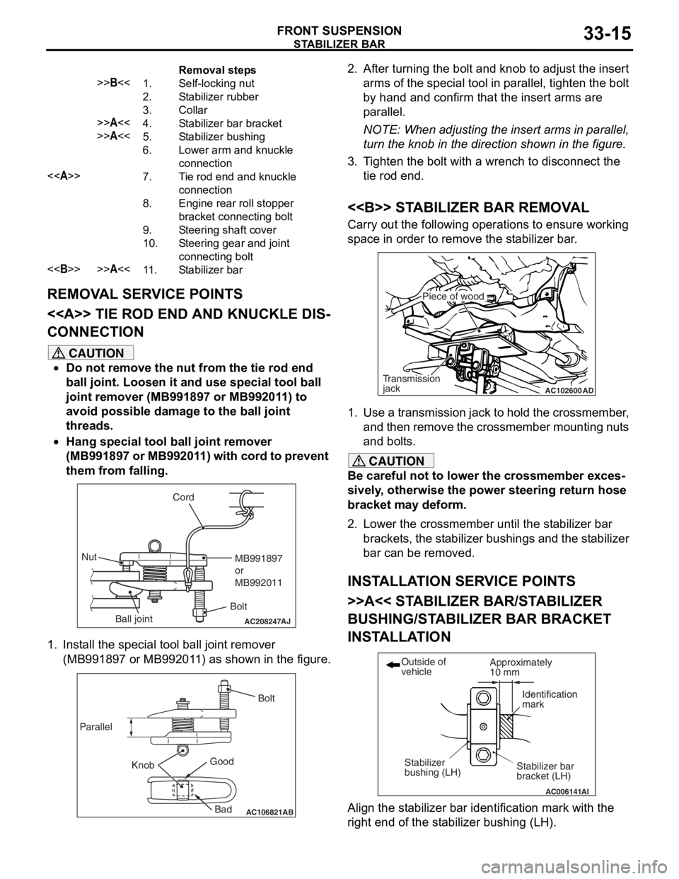
Removal steps
>>B<<1.Self-locking nut
2.Stabilizer rubber
3.Collar
>>A<<4.Stabilizer bar bracket
>>A<<5.Stabilizer bushing
6.Lower arm and knuckle
connection
<>7.Tie rod end and knuckle
connection
8.Engine rear roll stopper
bracket connecting bolt
9.Steering shaft cover
10.Steering gear and joint
connecting bolt
<>>>A<<11 .Stabilizer bar
STABILIZER BA R
FRONT SU SPENSION33-15
REMOVA L SER V ICE POINTS
<> TIE ROD END AND KNUCKLE DIS-
CONNECTION
CAUTION
•Do not remove the nut from the tie rod end
ball joint. Loosen it and use special tool ball
joint remover (MB991897 or MB992011) to
avoid possible damage to the ball joint
threads.
•
AC208247AJ
Cord
BoltMB991897
or
MB992011
Nut
Ball joint
Hang special tool ball joint remover
(MB991897 or MB992011) with cord to prevent
them from falling.
1. Install the special tool ball joint remover (MB991897 or MB992011) as shown in the figure.
AC106821
Knob
Parallel
Bolt
Good Bad
AB
2. After turning the bolt and knob to adjust the insert arms of the special tool in parallel, tighten the bolt
by hand and confirm that the insert arms are
parallel.
NOTE: When adjusting the insert arms in parallel,
turn the knob in the direction shown in the figure.
3. Tighten the bolt with a wrench to disconnect the tie rod end.
<> STABILIZER BAR REMOVAL
Carry out the following operations to ensure working
space in order to remove the stabilizer bar.
AC102600 AD
Piece of wood
Transmission
jack
1. Use a transmission jack to hold the crossmember,
and then remove the crossmember mounting nuts
and bolts.
CAUTION
Be careful not to lower the crossmember exces-
sively, otherwise the power steering return hose
bracket may deform.
2. Lower the crossmember until the stabilizer bar
brackets, the stabilizer bush ings and the stabilizer
bar can be removed.
INSTALLATION SERVICE POINTS
>>A<< STABILIZER BAR/STABILIZER
BUSHING/STABILIZ ER BAR BRACKET
INSTALLATION
AC006141 AI
Stabilizer bar
bracket (LH)
Outside of
vehicle
Stabilizer
bushing (LH) Approximately
10 mm
Identification
mark
Align the stabilizer bar iden
tification mark with the
right end of the stabilizer bushing (LH).
Page 404 of 800
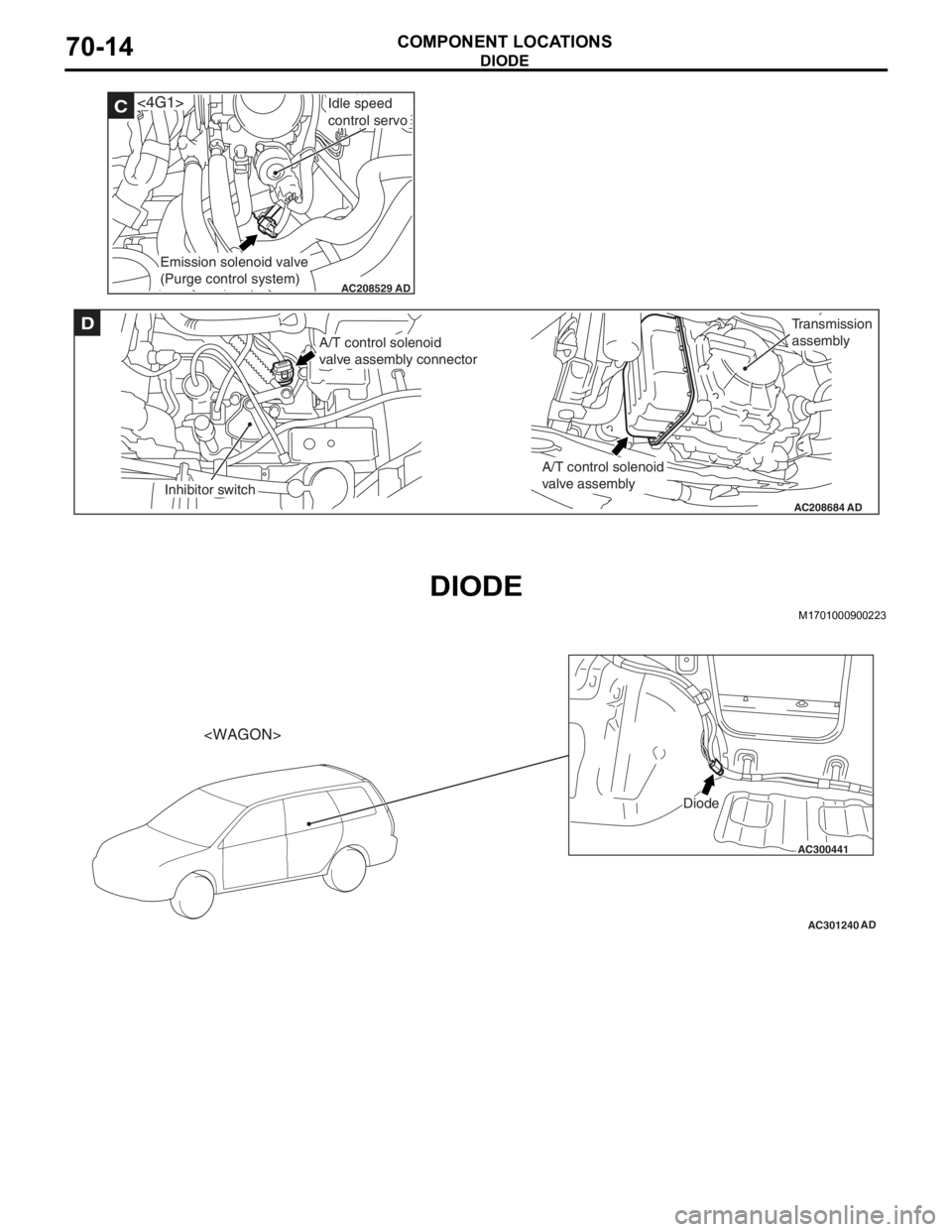
AC208529AD
C<4G1>Idle speed
control servo
Emission solenoid valve
(Purge control system)
AC208684
D
AD
A/T control solenoid
valve assembly connector
Inhibitor switch
A/T control solenoid
valve assembly
Transmission
assembly
DIOD E
COMPONENT LOCA TIONS70-14
DIODE
M1701 0009 0022 3
AC300441
AC301240
Diode
AD