ron MITSUBISHI LANCER 2006 Owner's Guide
[x] Cancel search | Manufacturer: MITSUBISHI, Model Year: 2006, Model line: LANCER, Model: MITSUBISHI LANCER 2006Pages: 800, PDF Size: 45.03 MB
Page 150 of 800
DRIVESHAFT ASSEMBLY
FRONT AXLE26-18
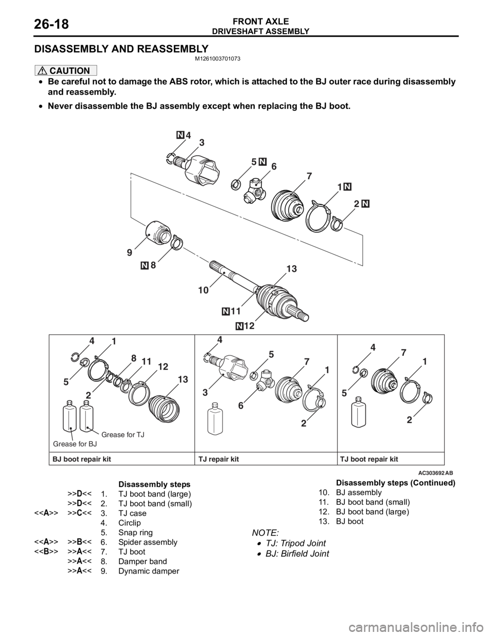
DISASSEMBLY AND REASSEMBLY
M1261003701073
CAUTION
•Be careful not to damage the ABS rotor, which is attached to the BJ outer race during disassembly
and reassembly.
•
AC303692
2
1
4
12
8
11
10
9 7
13
6
5N
N
N
3
N
N
2 1
4
13
8
11
12
5
21
4
7
6 5
3 21
4
7
5
AB
N
N
BJ boot repair kit TJ boot repair kit
TJ repair kit
Grease for TJ
Grease for BJ
Disassembly steps
>>D<<1.TJ boot band (large)
>>D<<2.TJ boot band (small)
<>>>C<<3.TJ case
4.Circlip
5.Snap ring
<>>>B<<6.Spider assembly
<>>>A<<7.TJ boot
>>A<<8.Damper band
>>A<<9.Dynamic damper
10.BJ assembly
11 .BJ boot band (small)
12.BJ boot band (large)
13.BJ boot
Never disassemble the BJ assembly except when replacing the BJ boot.
NOTE: .
•TJ: Tripod Joint
•BJ: Birfield Joint
Disassembly steps (Continued)
Page 151 of 800
DRIVESHAFT ASSEMBLY
FRONT AXLE26-19
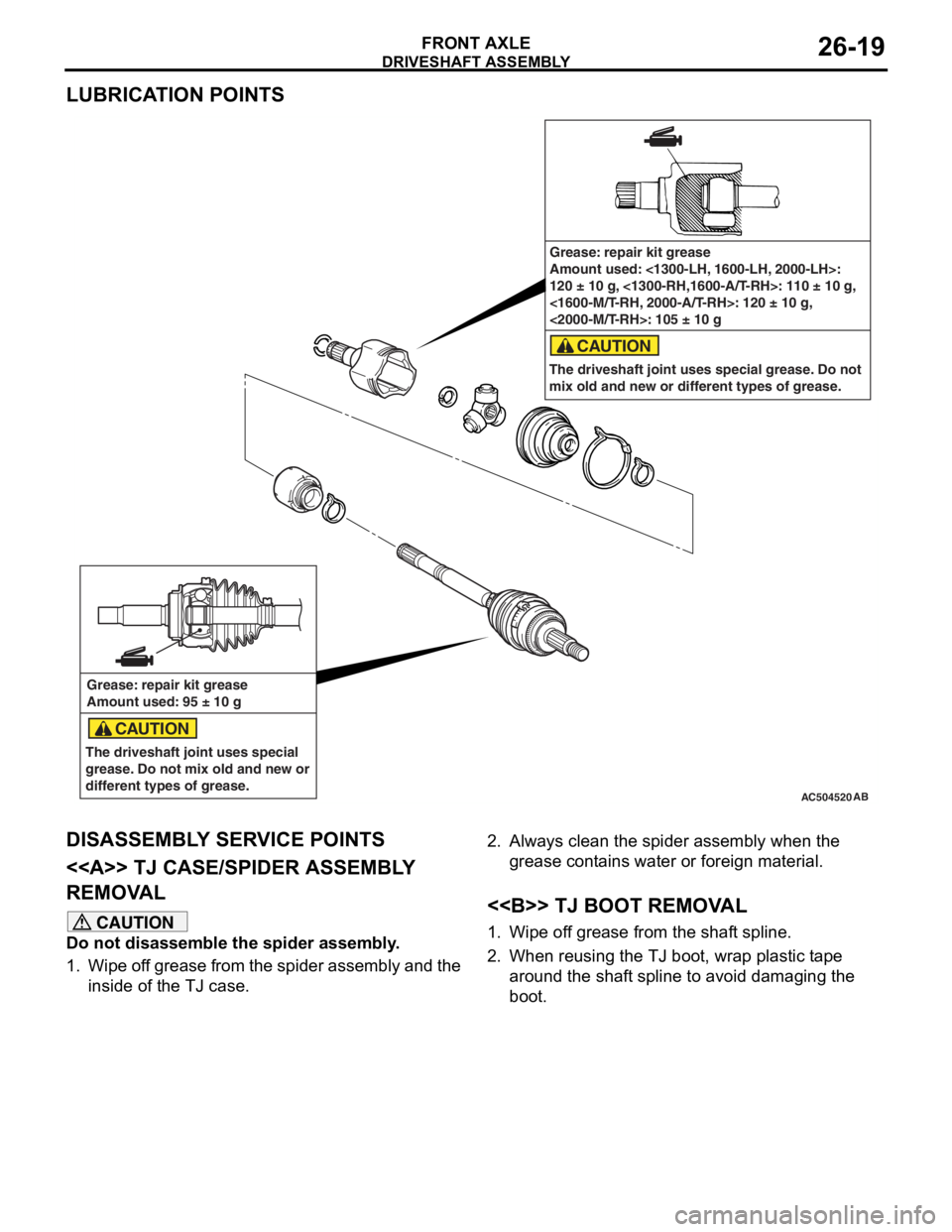
LUBRICATION POINTS
AC504520AB
Grease: repair kit grease
Amount used: 95 ± 10 g
The driveshaft joint uses special
grease. Do not mix old and new or
different types of grease.
CAUTION
Grease: repair kit grease
Amount used: <1300-LH, 1600-LH, 2000-LH>:
120 ± 10 g, <1300-RH,1600-A/T-RH>: 110 ± 10 g,
<1600-M/T-RH, 2000-A/T-RH>: 120 ± 10 g,
<2000-M/T-RH>: 105 ± 10 g
The driveshaft joint uses special grease. Do not
mix old and new or different types of grease.
CAUTION
DISASSEMBL Y SER V ICE POINTS
<> TJ CASE/SPIDER ASSEMBL Y
REMOV
A L
CAUTION
Do not disassemble the spider assembly.
1. Wipe off grease from the spider assembly and the inside of the TJ case.
2. Always clean the spider assembly when the
grease contains water or foreign material.
<> TJ BOOT REMOVAL
1. Wipe off grease from the shaft spline.
2. When reusing the TJ boot, wrap plastic tape around the shaft spline to avoid damaging the
boot.
Page 152 of 800
DRIVESHAFT ASSEMBLY
FRONT AXLE26-20
REASSEMBLY SERVICE POINTS
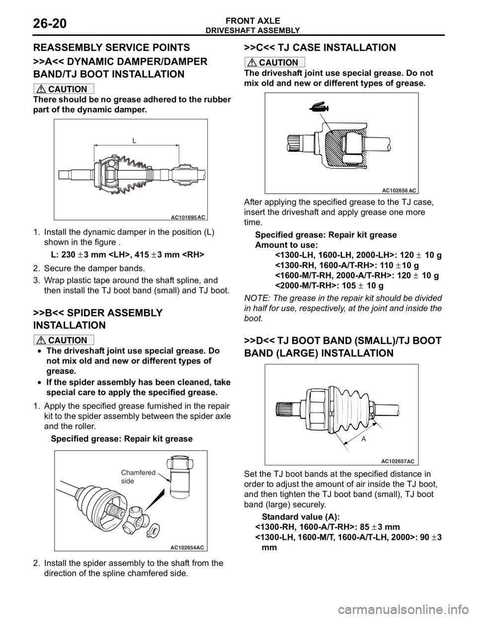
>>A<< DYNAMIC DAMPER/DAMPER
BAND/TJ BOOT INSTALLATION
CAUTION
There should be no grease adhered to the rubber
part of the dynamic damper.
AC101695AC
L
1. Install the dynamic damper in the position (L)
shown in the figure .
L: 230 ± 3 mm
2. Secure the damper bands.
3. Wrap plastic tape around the shaft spline, and then install the TJ boot band (small) and TJ boot.
>>B<< SPIDER ASSEMBLY
INSTALLATION
CAUTION
•The driveshaft joint use special grease. Do
not mix old and new or different types of
grease.
•If the spider assembly has been cleaned, take
special care to apply the specified grease.
1. Apply the specified grease furnished in the repair kit to the spider assembly between the spider axle
and the roller.
Specified grease: Repair kit grease
AC102654AC
Chamfered
side
2. Install the spider assembly to the shaft from the direction of the spline chamfered side.
>>C<< TJ CASE INSTALLATION
CAUTION
The driveshaft joint use special grease. Do not
mix old and new or different types of grease.
AC102656AC
After applying the specified grease to the TJ case,
insert the driveshaft and apply grease one more
time.
Specified grease: Repair kit grease
Amount to use:
<1300-LH, 1600-LH, 2000-LH>: 120 ± 10 g
<1300-RH, 1600-A/T-RH>: 110 ± 10 g
<1600-M/T-RH, 2000-A/T-RH>: 120 ± 10 g
<2000-M/T-RH>: 105 ± 10 g
NOTE: The grease in the repair kit should be divided
in half for use, respectively, at the joint and inside the
boot.
>>D<< TJ BOOT BAND (SMALL)/TJ BOOT
BAND (LARGE) INSTALLATION
AC102657
A
AC
Set the TJ boot bands at the specified distance in
order to adjust the amount of air inside the TJ boot,
and then tighten the TJ boot band (small), TJ boot
band (large) securely.
Standard value (A):
<1300-RH, 1600-A/T-RH>: 85 ± 3 mm
<1300-LH, 1600-M/T, 1600-A/T-LH, 2000>: 90 ± 3
mm
Page 153 of 800
DRIVESHAFT ASSEMBLY
FRONT AXLE26-21
INSPECTION
M1261003800130
•Check the driveshaft for damage, bending or cor-
rosion.
•Check the driveshaft spline part for wear or dam-
age.
•Check the spider assembly for roller rotation,
wear or corrosion.
•Check the groove inside TJ case for wear or cor-
rosion.
•Check the dynamic damper for damage or crack-
ing.
•Check the boots for deterioration, damage or
cracking.
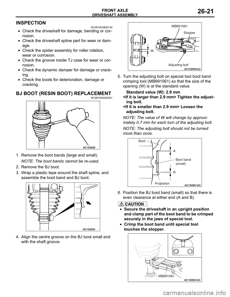
BJ BOOT (RESIN BOOT) REPLACEMENTM1261005200361
AC102658
1.Remove the bo ot ban ds (large a nd small).
NOTE: The boot ba nds canno t be re -used .
2.Remove the BJ boot.
3.W r ap a plastic t a pe arou nd the shaf t spline, an d
asse mble the b oot ba nd and BJ boo t.
AC102659
4.Align th e ce ntre gro o ve o n the BJ boot small end
wit h the shaf t groo ve.
AC102660
WMB991561
Stopper
Adjusting bolt
AC
5. T u rn the ad justing bolt o n sp ecial too l boo t band
crimping tool (MB9915 61) so that the size of the
o penin g (W) is at t he st and ard value .
St andard va lue (W): 2 . 9 mm
ing bolt.
adjustin g bolt.
NOTE: The value of W will chang e by approxi-
mately 0.7 mm for ea ch tu rn of th e adjusting bolt.
NOTE: The ad justing bolt shou ld no t be tu rned
more th an once.
AC102661AC
Boot
ABoot band
(small)
B
Projection
6. Position the BJ boo t band (small) so th at there is
e v en clea rance at either en d (A and B).
CAUTION
•Secure the driveshaft in an upright position
and clamp part of the boot band to be crimped
securely in the jaws of special tool.
•
AC102663 ACMB991561
Crimp the boot band until special tool
touches the stopper.
Page 154 of 800
DRIVESHAFT ASSEMBLY
FRONT AXLE26-22
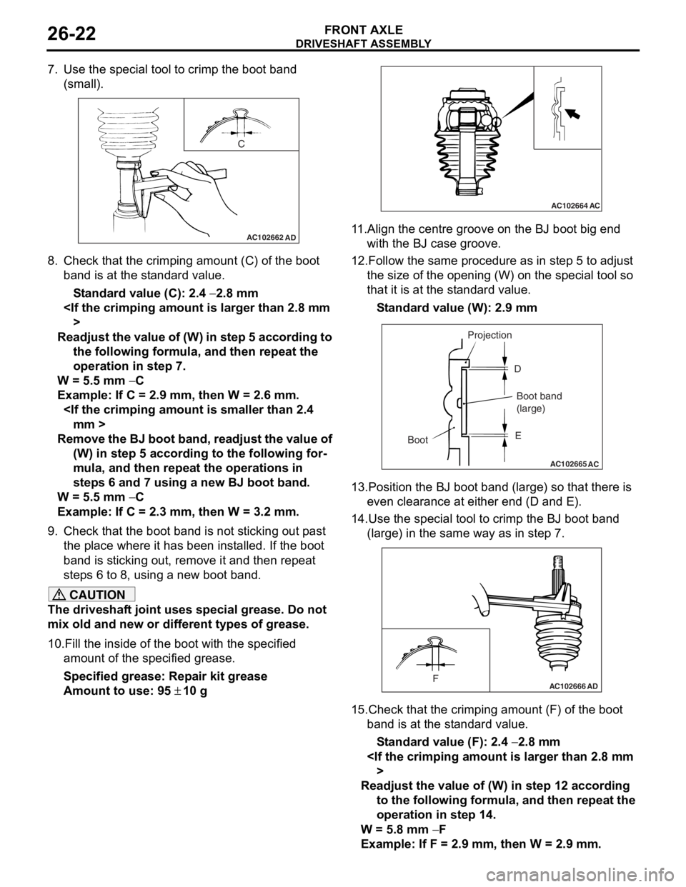
7. Use the special tool to crimp the boot band (small).
AC102662
C
AD
8.Check t hat the crimpin g amount (C) of the bo ot
ba nd is at th e st and ard value.
St andard va lue (C): 2.4 − 2.8 mm
Readjust th e value of (W) in s t ep 5 acc ord i ng to
the following fo rm ula, and then repea t the
operation in step 7.
W = 5.5 mm − C
Example : If C = 2.9 mm, the n W = 2.6 mm.
Rem o v e the BJ bo ot ba nd , re ad ju st the v a l ue of
(W) in ste p 5 acc ord i ng to the following for
-
mula, and then repe at the o perations i n
step
s 6 and 7 using a new BJ boot band .
W = 5.5 mm − C
Example : If C = 2.3 mm, the n W = 3.2 mm.
9.Check t hat the boot b and is no t sticking o u t p a st
th e pla c e wher e it h a s be en in st alled. If t he boo t
ba nd is st icking out, remove it a nd the n repea t
step s 6 to 8, u s in g a new b oot ban d.
CAUTION
The driveshaft joint uses special grease. Do not
mix old and new or different types of grease.
10.Fill the inside of the boot with the specified amount of the specified grease.
Specified grease: Repair kit grease
Amount to use: 95 ± 10 g
AC102664AC
11.Align the centre groove on the BJ boot big end with the BJ case groove.
12.Follow the same procedure as in step 5 to adjust
the size of the opening (W) on the special tool so
that it is at the standard value.
Standard value (W): 2.9 mm
AC102665 AC
Boot Projection
Boot band
(large)
D
E
13.Position the BJ boot band (large) so that there is even clearance at either end (D and E).
14.Use the special tool to crimp the BJ boot band
(large) in the same way as in step 7.
AC102666FAD
15.Check that the crimping amount (F) of the boot band is at the standard value.
Standard value (F): 2.4 − 2.8 mm
Readjust the value of (W) in step 12 according to the following formula, and then repeat the
operation in step 14.
W = 5.8 mm − F
Example: If F = 2.9 mm, then W = 2.9 mm.
Page 155 of 800
DRIVESHAFT ASSEMBLY
FRONT AXLE26-23
Remove the BJ boot band, readjust the value of
(W) in step 12 according to the following for
-
mula, and then repeat the operations in
steps 13 and 14 using a new BJ boot band.
W = 5.8 mm − F
Example: If F = 2.3 mm, then W = 3.5 mm.
16.Check that the boot band is not sticking out past
the place where it has been installed. If the boot
band is sticking out, remove it and then repeat
steps 13 to 15, using a new boot band.
Page 159 of 800
SPECIAL TOOLS
REAR AXLE27-3
SPECIAL TOOLS
M1271000600495
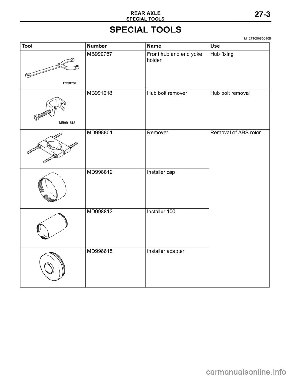
ToolNumberNameUse
B990767
MB990767Front hu b and end yoke
holde
rHub fixin g
MB991618
MB991618Hub bolt remo verHub bolt remova l
MD998801Remov e rRemoval of ABS rotor
MD998812Installer cap
MD9988 13Installer 100
MD9988 15Installer ada pter
Page 160 of 800
ON-VEHICLE SERVICE
REAR AXLE27-4
ON-VEHICLE SERVICE
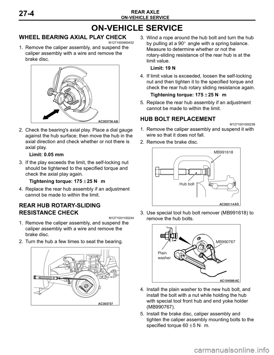
WHEEL BEARING AXIAL PLAY CHECKM1271000900452
1. Remove the caliper assembly, and suspend the caliper assembly with a wire and remove the
brake disc.
AC303736AB
2.Check the be aring ' s axial play . Place a dial gau ge
ag ainst th e hub su rface; then mo ve t he hu b in the
axial dire ction and check whe t her or not the r e is
axial pla y .
Limit: 0.05 mm
3.If the play e xce eds the limit, the self -lockin g nut
should be tighte ned to the specified torque and
check the axial play again .
Ti ghte n ing torque: 175 ± 25 N⋅m
4.Replace the re ar hub a s sembly if an ad justmen t
cannot be made to within the limit.
REAR HUB ROTA R Y -SLIDING
RESIST
ANCE CHECK
M127100 1 1 0024 4
1.Remove the caliper assembly , a nd suspe nd the
caliper assembly with a wire an d remove t he
bra k e d i sc.
2.T u rn the hu b a few times to seat th e bea ring.
AC303737
3.Wind a rope a r ound the hu b bolt and turn t he hub
b y pullin g at a 90
° angle with a spring balance.
Measure to d
e
termine whe t her or not the
ro
t
a
ry-sliding resist an ce of the rea r hub is at the
limit va
lue.
Limit: 19 N
4.If limit value is exceeded , loo s en the self-locking
n u t and then tighten it to the specified torque and
check the rear hu b rot a ry sliding resist ance again.
Ti ghte n ing torque: 175 ± 25 N⋅m
5.Replace the re ar hub assembly if an a d justmen t
canno t be made to within the limit.
HUB BOLT REPLACEMENTM12710010 0025 8
1.Remove the calip er assembly and suspe nd it with
wire so t hat it does not fa ll.
2.Remove the bra k e d i sc.
AC302114
MB991618
AD
Hub bolt
3.Use spe c ia l too l hub bolt remover (MB99161 8) to
re move the h ub bo lt s.
AC104588
MB990767
Plain
washer
AC
4. In st all the plain wa sher to the n e w hub b o lt, a nd
inst all the bolt with a nu t while hold i ng the hub
wit h spe c ia l too l fron t hub a nd end yoke holder
(MB99076 7).
5.In st all the bra k e d i sc, ca lip er assembly and
tighten th e caliper assembly mount ing bolt s to the
specifie d torqu e 60
± 5 N⋅m.
Page 162 of 800
REAR AXLE HUB ASSEMBLY
REAR AXLE27-6
<
AC210936AC
MD998815
MD998801 MD998813
MD998812
Rear hub assembly
ABS rotor
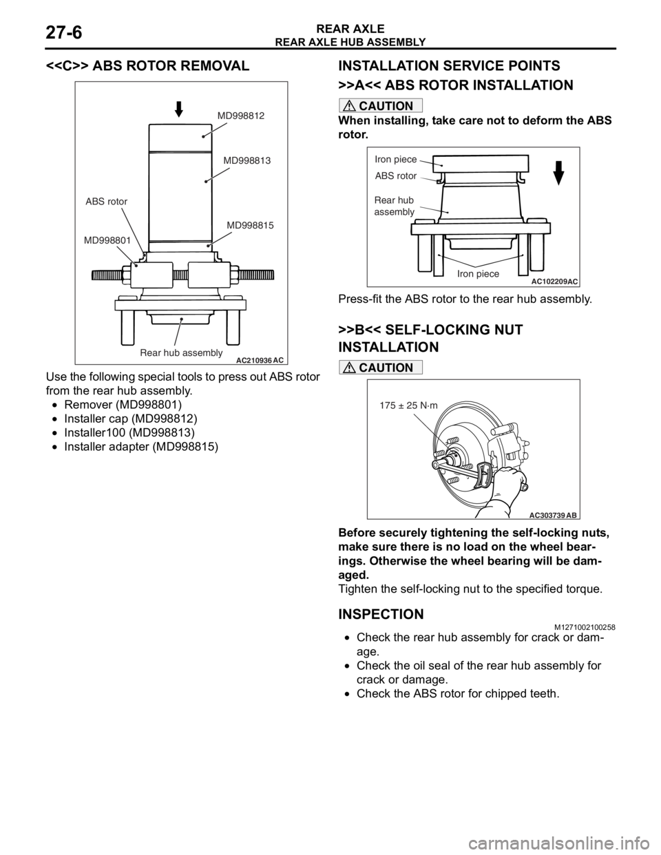
Use
the fo llowing specia l to ols t o press o u t ABS rot o r
from th
e rear h ub assembly .
•Remover (MD99880 1)
•Insta lle r cap (MD9988 12)
•Insta lle r100 (MD9 98813 )
•Insta lle r adapte r (MD998 815)
INSTALLA T ION SER VICE POINTS
>>A<< ABS ROTO R INST ALLA TION
CAUTION
When installing, take care not to deform the ABS
rotor.
AC102209
Iron piece
ABS rotor
Rear hub
assembly
Iron piece
AC
Press-fit the ABS rotor to the rear hub assembly.
>>B<< SELF-LOCKING NUT
INSTALLATION
AC303739
175 ± 25 N·m
AB
CAUTION
Before securely tightening the self-locking nuts,
make sure there is no load on the wheel bear
-
ings. Otherwise the wheel bearing will be dam-
aged.
Tighten the self-locking nut to the specified torque.
INSPECTIONM1271002100258
•Check the rear hub assembly for crack or dam-
age.
•Check the oil seal of the rear hub assembly for
crack or damage.
•Check the ABS rotor for chipped teeth.
Page 165 of 800
TROUBLESHOOTING
WHEEL AND TYRE31-3
TROUBLESHOOTING
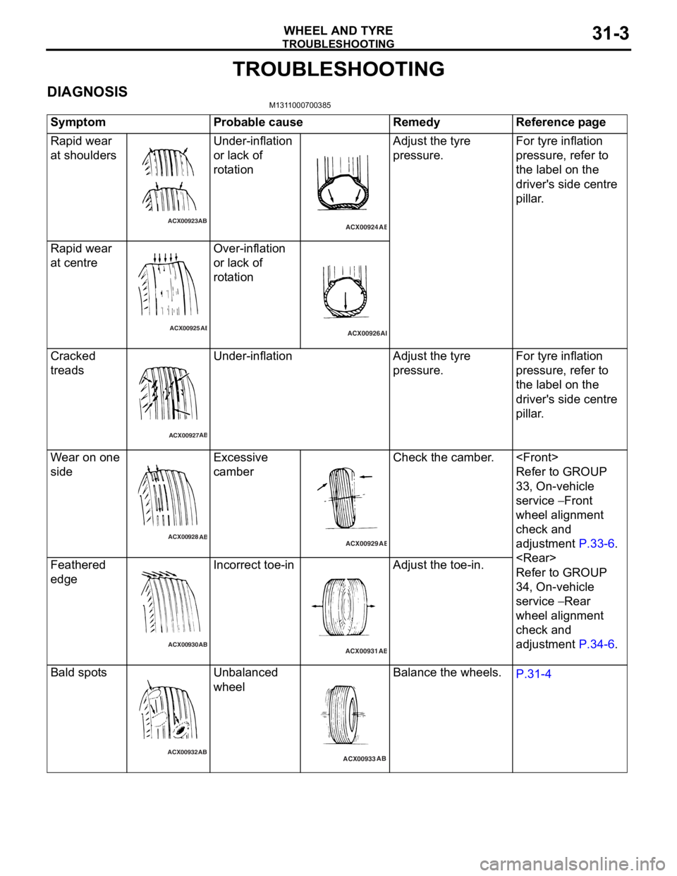
DIAGNOSISM1311000700385
SymptomProbable causeRemedyReference page
Rapid wear
at shoulders
ACX00923AB
Unde
r-inflation
or lack
of
rot
a tion
ACX00924 AB
Adjust the tyre
pre
ssu re.For tyre inflation
pressure, refer to
th
e lab e l on the
driver'
s side centre
pi
lla r .
Rapi d wear
at ce
ntre
ACX00925 AB
Over-infla
tion
or lack
of
rot
a tion
ACX00926 AB
Cra
cke d
treads
ACX00927 AB
Unde
r-inflationAdjust th e tyre
pre
ssu re.For tyre inflation
pressure, refer to
th
e lab e l on the
driver'
s side centre
pi
lla r .
Wear o n one
side
ACX00928
AB
Excessive
cam
b er
ACX00929 AB
Check the camber .
Refer to GROUP
33
, On -vehicle
serv
ic e
− Front
whee
l alignment
check and
ad
justmen t
P.33-6.
Refer to GROUP
34
, On -vehicle
serv
ic e
− Rear
whee
l alignment
check and
ad
justmen t
P.34-6.
Feather ed
edge
ACX00930 AB
In
correct toe- in
ACX00931
AB
Adjust the toe-in.
Bald spot s
ACX00932 AB
Unba
lanced
whee
l
ACX00933 AB
Balance
the whee ls.P.31-4