ron MITSUBISHI LANCER 2006 Manual PDF
[x] Cancel search | Manufacturer: MITSUBISHI, Model Year: 2006, Model line: LANCER, Model: MITSUBISHI LANCER 2006Pages: 800, PDF Size: 45.03 MB
Page 243 of 800
ON-VEHICLE SERVICE
POWER STEERING37-13
STEERING WHEEL RETURN TO CENTRE
CHECK
M1372001800317
Conduct a road test:
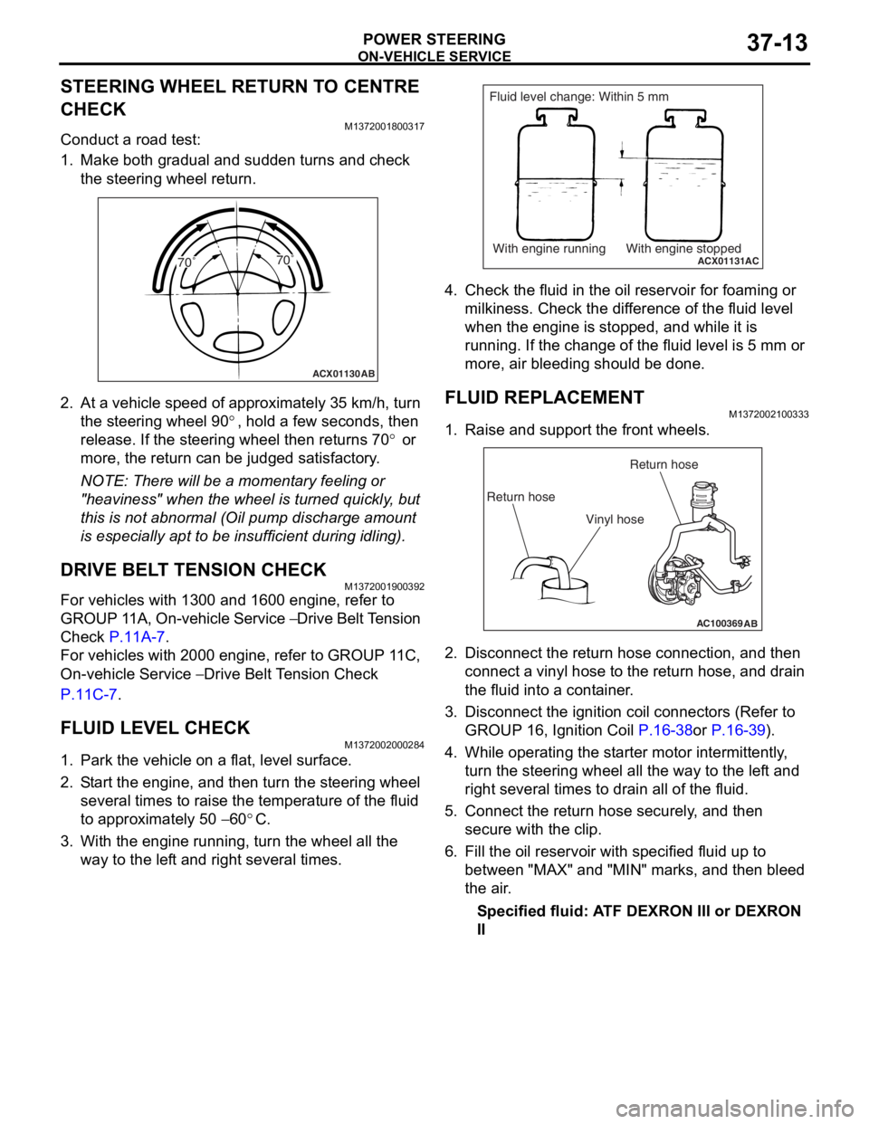
1. Make both gradual and sudden turns and check the steering wheel return.
ACX01130 AB
70˚ 70˚
2.
At a vehicle sp eed of a pproxima t ely 35 km/h, turn
th e ste e ring wh eel 9 0
°, ho ld a few se cond s, the n
release. If th
e ste
e
ring
wh eel t hen ret u rns 7 0
° or
more, th
e return
can
be ju
dged satisfactory
.
NOTE: There will be a mome nt a r y fee lin g or
"he
a
viness" when t he wheel is turned quickly , but
th
is is n o t abno rmal (Oil pu mp discharge amou nt
is especially a p t to b e insufficie n t during id lin g).
DRIVE BELT TENSION CHECK
M13720019 0039 2
For vehicles with 13 00 and 1600 engin e , refer to
GROUP 1
1 A, On-vehicle Service
− Drive Belt T ension
Che
c
k
P.11A-7.
For veh i cles wit h 2000 e ngin e , refer to GROUP 1 1 C,
On-vehicle Se
rvice
− Drive Belt Te nsion Check
P.1 1 C - 7.
FLUID LEVEL CHECK
M13720020 0028 4
1.Park the vehicle on a f l at, leve l su rface .
2.S t art the engine, and t hen tu rn the ste e ring wheel
seve ral times to raise the temperat ure of th e flu i d
to approximately 50
− 60°C.
3.With the engine run n ing, turn the wheel all the
way to the lef t an d righ t several times.
ACX01131With engine running With engine stoppedAC
Fluid level change: Within 5 mm
4.Check t he flu i d in the oil r e servoir f o r foaming or
milkine s s. Check the d i f f e r ence of the fluid le vel
when the e ngine is stop ped, an d while it is
ru nning . If the chan ge of th e fluid le vel is 5 mm or
more, a i r bleedin g sh ould be don e.
FLUID REPLACEMENT
M13720021 0033 3
1.Raise a nd su pport t he fron t wheels.
AC100369AB
Return hoseReturn hose
Vinyl hose
2. Disco nnect the re turn hose connection , and then
conne ct a vinyl hose to the re turn h o se, and drain
th e flu i d into a cont ain e r .
3.Disco nnect the ignition coil con necto rs (Refe r to
GROUP 16, Ignition Coil
P.16-38or P.16-39).
4.Wh ile operat ing th e st arter moto r inter m itt ently ,
tu rn the steering whee l all the wa y to t he le f t a nd
right seve ral times to dra i n all of the fluid.
5.Conn ect the retu rn hose se curely , and then
secu re with t he clip.
6.Fill the oil reservo i r with specified fluid u p to
b e tween "MAX" and "MIN" marks, and then bleed
th e air .
Specified fluid: A TF DEXRON III or DEXRON
II
Page 244 of 800
ON-VEHICLE SERVICE
POWER STEERING37-14
POWER STEERING SYSTEM AIR
BLEEDING
M1372002200330
Perform air bleeding procedure as necessary after
replacing the steering gear or the steering fluid lines.
1. Raise and support the front wheels.
2. Disconnect the ignition coil connectors (Refer to GROUP 16, Ignition Coil
P.16-38 or P.16-39).
CAUTION
Perform air bleeding only while cranking the
engine. If air bleeding is performed while the
engine is running, air could enter the fluid. Dur
-
ing air bleeding, refill the steering fluid supply so
that the level never falls below the "MIN" mark on
the oil reservoir.
3. Turn the steering wheel all the way to the left and
right five or six times wh ile using the starter motor
to crank the engine intermittently several times
(for 15 to 20 seconds).
4. Connect the ignition coil connectors (Refer to GROUP 16, Ignition Coil
P.16-38 or P.16-39).
5. Start the engine (idling).
6. Turn the steering wheel to the left and right until there are no air bubbles in the oil reservoir.
7. Confirm that the fluid is not milky, and that the level is between "MAX" and "MIN" marks.
8. Confirm that there is very little change in the fluid
level when the steering wheel is turned left and
right.
CAUTION
If the fluid level rises suddenly after the engine is
stopped, the air has not been completely bled. If
air bleeding is not complete, there will be abnor
-
mal noises from the pump and the flow-control
valve, and this condition could cause reduce the
life of the power steering components.
ACX01131With engine running With engine stoppedAC
Fluid level change: Within 5 mm
9. Confirm that the change in the fluid level is no more than 5 mm when the engine is stopped and
when it is running.
10.If the change of the fluid level is 5 mm or more,
the air has not been completely bled from the
system. The air bleeding procedure must be
repeated.
OIL PUMP PRESSURE TEST
M1372002300315
ACX01133
Temperature
gauge
Oil reservoir
Adapter
(MB991548)
Oil
pump Adapter
(MB991549)
AB
Shut-off valve
(fully closed)
Pressure
gauge
(MB990662)
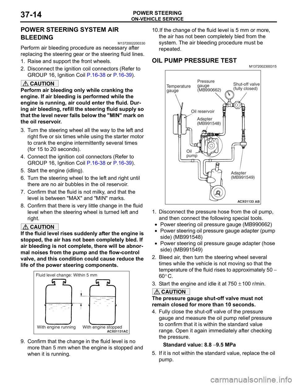
1. Disconnect the pressure hose from the oil pump,
and then connect the following special tools.
•Power steering oil pressure gauge (MB990662)
•Power steering oil pressure gauge adapter (pump
side) (MB991548)
•Power steering oil pressure gauge adapter (hose
side) (MB991549)
2. Bleed air, then turn the steering wheel several times while the vehicle is not moving so that the
temperature of the fluid rises to approximately 50
−
60
°C.
3. Start the engine and idle it at 750 ± 100 r/min.
CAUTION
The pressure gauge shut-off valve must not
remain closed for more than 10 seconds.
4. Fully close the shut-off valve of the pressure gauge and measure the oil pump relief pressure
to confirm that it is within the standard value
range. Open it again immediately after checking
the pressure.
Standard value: 8.8 − 9.5 MPa
5. If it is not within the standard value, replace the oil pump.
Page 251 of 800
AC210969AD
Clip
Steering column
shaft
STE E RING C O LUMN SHAFT AS SEMBL Y
POWER STEERING37-21
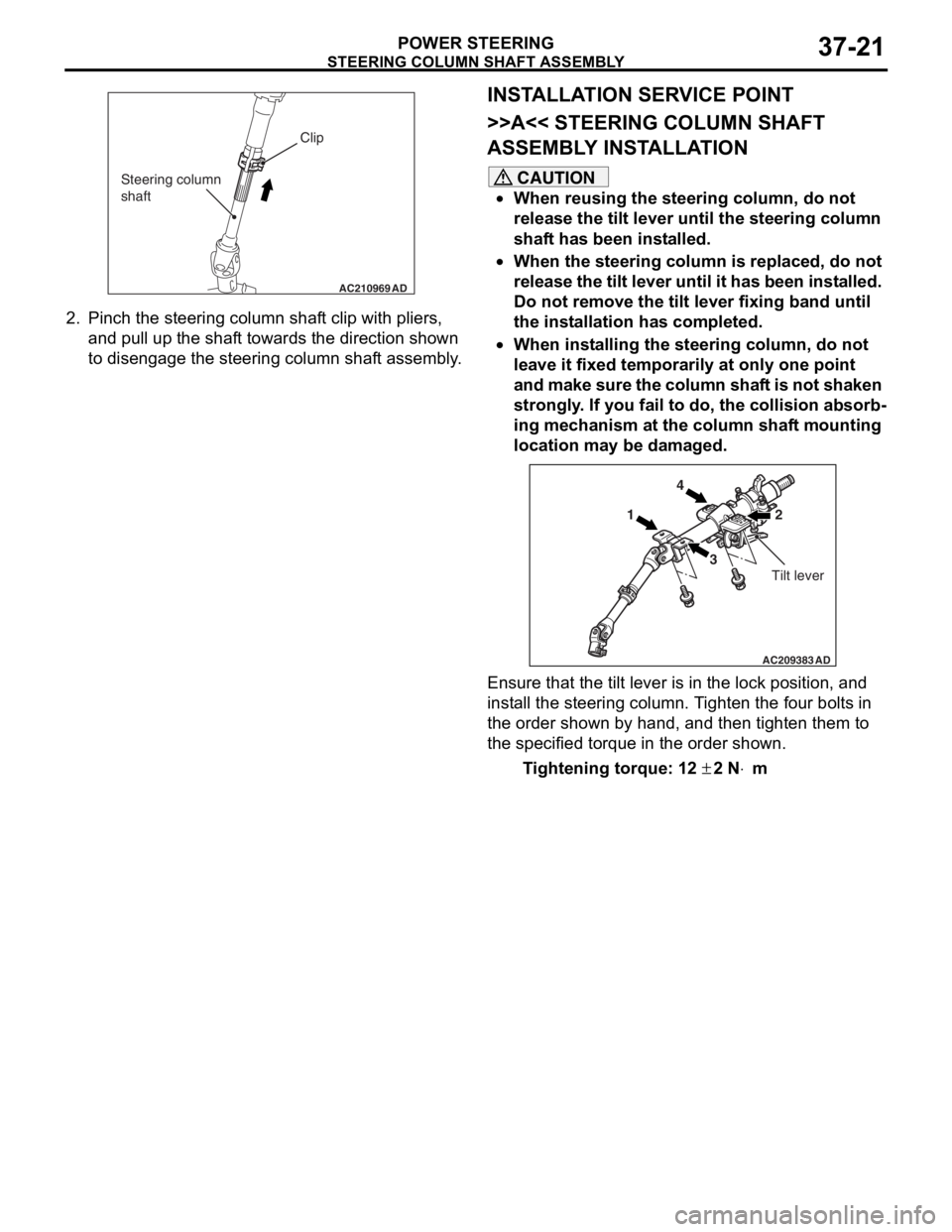
2.Pin c h t he st eering column shaf t clip with pliers,
an d pull up the shaf t towards the d i rection shown
to disengag e the steering column shaf t assembly .
INSTALLA T ION SER VICE POINT
>>A<< STEERING COLUMN SHAFT
ASSEMBL
Y INST ALLA TION
CAUTION
•When reusing the steering column, do not
release the tilt lever until the steering column
shaft has been installed.
•When the steering column is replaced, do not
release the tilt lever until it has been installed.
Do not remove the tilt lever fixing band until
the installation has completed.
•When installing the steering column, do not
leave it fixed temporarily at only one point
and make sure the column shaft is not shaken
strongly. If you fail to do, the collision absorb
-
ing mechanism at the column shaft mounting
location may be damaged.
AC209383AD
14
3 2
Tilt lever
Ensure that the tilt lever is in the lock position, and
install the steering column. Tighten the four bolts in
the order shown by hand, and then tighten them to
the specified torque in the order shown.
Tightening torque: 12 ± 2 N⋅m
Page 253 of 800
POWER STEERING GEAR BOX AND LINKAGE
POWER STEERING37-23
POWER STEERING GEAR BOX AND LINKAGE
REMOVAL AND INSTALLATIONM1372010900237
WARNING
Before removing the steering gear, refer to GROUP 52B, Service Precautions (P.52B-5) and
Air Bag Module and Clock Spring (P.52B-194). Centre the front wheels. Failure to do so may
damage the SRS clock spring and render the SRS system inoperative, risking serious injury.
Pre-removal Operation
•Power Steering Fluid Draining (Refer to P.37-13.)
Post-installation Operation
•Check the dust cover for cracks or damage by pushing it
with your finger.
•Power Steering Fluid Supplying (Refer to P.37-13.)
•Power Steering Fluid Line Bleeding (Refer to P.37-14.)
•Checking Steering Wheel Position with Wheels Straight
Ahead.
•Front Wheel Alignment Adjustment (Refer to GROUP 33,
On-vehicle Service
− Front Wheel Alignment Check and
Adjustment
P.33-6.)
AC304920 AB
57 ± 7 N·m
15 ± 3 N·m
70 ± 10 N·m
7
3
8
5
6
9
10 24
1
12 ± 2 N·m
12 ± 2 N·m
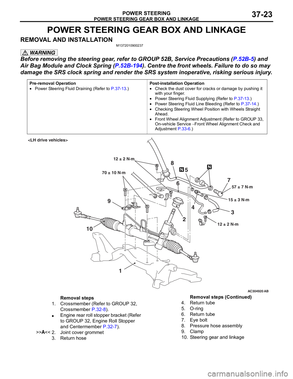
Removal steps
1.Crossmember (Refer to GROUP 32,
Crossmember
P.32-8).
•Engine rear roll stopper bracket (Refer
to GROUP 32, Engine Roll Stopper
and Centermember
P.32-7).
>>A<<2.Joint cover grommet
3.Return hose
4.Return tube
5.O-ring
6.Return tube
7.Eye bolt
8.Pressure hose assembly
9.Clamp
10.Steering gear and linkage
Removal steps (Continued)
Page 258 of 800
POWER STEERING GEAR BOX AND LINKAGE
POWER STEERING37-28
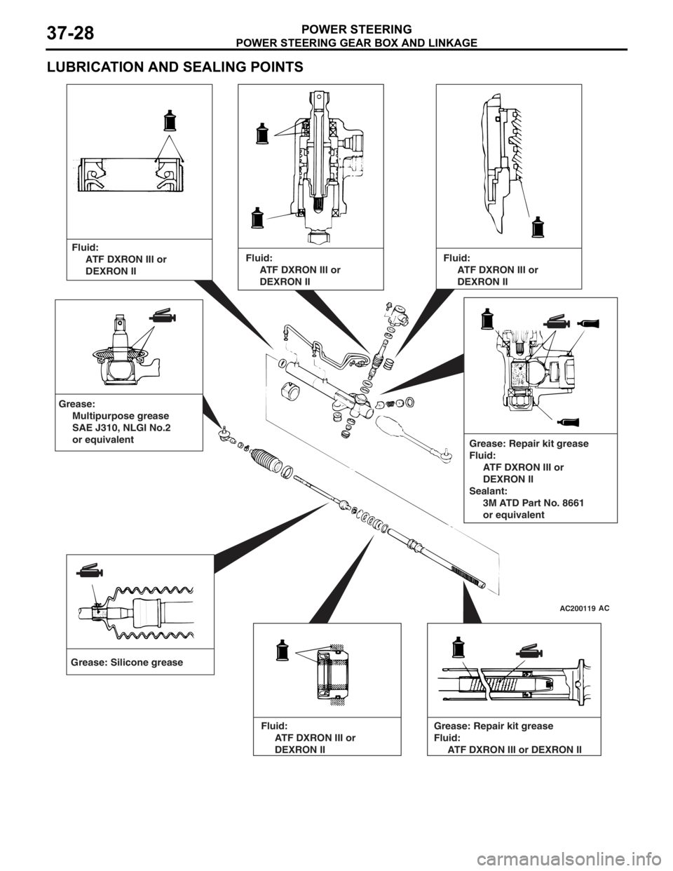
LUBRICATION AND SEALING POINTS
AC200119AC
Grease: Silicone greaseFluid:
ATF DXRON III or
DEXRON II
Grease: Repair kit grease
Fluid:
ATF DXRON III or
DEXRON II
Sealant:
3M ATD Part No. 8661
or equivalent
Grease:
Multipurpose grease
SAE J310, NLGI No.2
or equivalent
Fluid:
ATF DXRON III or
DEXRON II
Fluid:
ATF DXRON III or
DEXRON II
Fluid:
ATF DXRON III or
DEXRON II Grease: Repair kit grease
Fluid:
ATF DXRON III or DEXRON II
Page 260 of 800
POWER STEERING GEAR BOX AND LINKAGE
POWER STEERING37-30
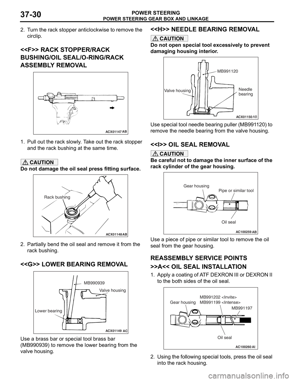
2. Turn the rack stopper anticlockwise to remove the circlip.
<
BUSHING/OIL SEAL/O-RING/RACK
ASSEMBLY REMOVAL
ACX01147 AB
1.
Pull out th e rack slo w ly . T a ke out th e rack stop per
an d the rack bushing at the same time.
CAUTION
Do not damage the oil seal press fitting surface.
ACX01148AB
Rack bushing
2. Partially bend the oil seal and remove it from the
rack bushing.
<
ACX01149
MB990939
Lower bearing
AC
Valve housing
Use a brass bar or special tool brass bar
(MB990939) to remove the lower bearing from the
valve housing.
<
CAUTION
Do not open special tool excessively to prevent
damaging housing interior.
ACX01150 AB
Valve housing MB991120Needle
bearing
Use special tool needle bearing puller (MB991120) to
remove the needle bearing from the valve housing.
<> OIL SEAL REMOVAL
CAUTION
Be careful not to damage the inner surface of the
rack cylinder of the gear housing.
AC100259
Oil seal
Pipe or similar tool
Gear housing
AB
Use a piece of pipe or simila
r tool to remove the oil
seal from the gear housing.
REASSEMBLY SERVICE POINTS
>>A<< OIL SEAL INSTALLATION
1. Apply a coating of ATF DEXRON III or DEXRON II to the both sides of the oil seal.
AC100260AI
Oil seal
MB991202
MB991199
Gear housing
MB991197
2. Using the following special tools, press the oil seal
into the rack housing.
Page 261 of 800
POWER STEERING GEAR BOX AND LINKAGE
POWER STEERING37-31
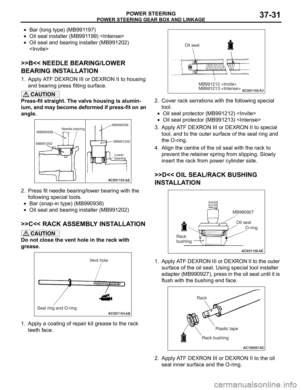
•Bar (long type) (MB991197)
•Oil seal installer (MB991199)
•Oil seal and bearing installer (MB991202)
>>B<< NEEDLE BEARING/LOWER
BEARING INSTALLATION
1. Apply ATF DEXRON III or DEXRON II to housing and bearing press fitting surface.
CAUTION
Press-fit straight. The valve housing is alumin-
ium, and may become deformed if press-fit on an
angle.
ACX01153
Needle bearing
MB990938
MB991202 MB991202
Lower
bearing
AE
MB990938
2. Press fit needle bearing/lower bearing with the
following special tools.
•Bar (snap-in type) (MB990938)
•Oil seal and bearing installer (MB991202)
>>C<< RACK ASSEMBLY INSTALLATION
CAUTION
Do not close the vent hole in the rack with
grease.
ACX01154 AB
Seal ring and O-ring Vent hole
1. Apply a coating of repair kit grease to the rack
teeth face.
ACX01155
MB991212
MB991213
AJ
Oil seal
2. Cover rack serrations with the following special tool.
•Oil seal protector (MB991212)
•Oil seal protector (MB991213)
3. Apply ATF DEXRON III or DEXRON II to special
tool, and to the outer surface of the seal ring and
the O-ring.
4. Align the centre of the oil seal with the rack to prevent the retainer spring from slipping. Slowly
insert the rack from power cylinder side.
>>D<< OIL SEAL/RACK BUSHING
INSTALLATION
ACX01156 AE
Oil seal
O-ring
MB990927
Rack
bushing
1. Apply ATF DEXRON III or DEXRON II to the outer surface of the oil seal. Using special tool installer
adapter (MB990927), press in the oil seal until it is
flush with the bushing end face.
AC100261 AC
Rack
Plastic tape
Rack bushing
2. Apply ATF DEXRON III or DEXRON II to the oil seal inner surface and the O-ring.
Page 262 of 800
POWER STEERING GEAR BOX AND LINKAGE
POWER STEERING37-32
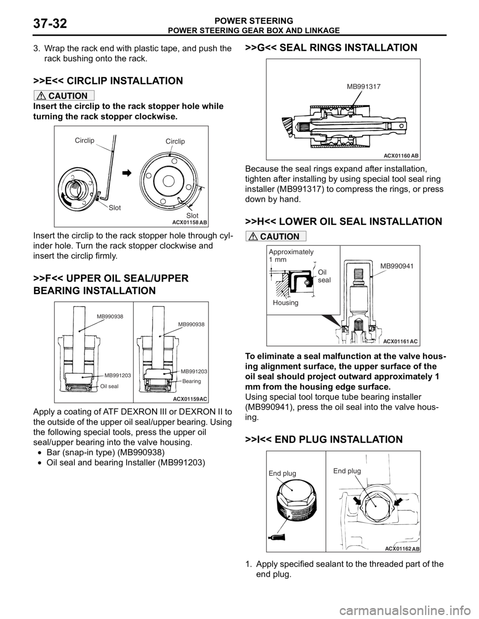
3. Wrap the rack end with plastic tape, and push the rack bushing onto the rack.
>>E<< CIRCLIP INSTALLATION
CAUTION
Insert the circlip to the rack stopper hole while
turning the rack stopper clockwise.
ACX01158
Circlip
Slot
AB
Circlip
Slot
Insert the circlip to the rack stopper hole through cyl-
inder hole. Turn the rack stopper clockwise and
insert the circlip firmly.
>>F<< UPPER OIL SEAL/UPPER
BEARING INSTALLATION
ACX01159AC
MB990938
MB991203
Oil seal
MB991203 Bearing
MB990938
Apply a coating of ATF DEXRON III or DEXRON II to
the outside of the upper oil seal/upper bearing. Using
the following special tools, press the upper oil
seal/upper bearing into the valve housing.
•Bar (snap-in type) (MB990938)
•Oil seal and bearing Installer (MB991203)
>>G<< SEAL RINGS INSTALLATION
ACX01160
AB
MB991317
Because the seal rings expand after installation,
tighten after installing by using special tool seal ring
installer (MB991317) to compress the rings, or press
down by hand.
>>H<< LOWER OIL SEAL INSTALLATION
ACX01161
Housing
AC
Oil
seal
Approximately
1 mm
MB990941
CAUTION
To eliminate a seal malfunction at the valve hous-
ing alignment surface, the upper surface of the
oil seal should project outward approximately 1
mm from the housing edge surface.
Using special tool torque tube bearing installer
(MB990941), press the oil seal into the valve hous
-
ing.
>>I<< END PLUG INSTALLATION
ACX01162
AB
End plug End plug
1. Apply specified sealant to the threaded part of the
end plug.
Page 267 of 800
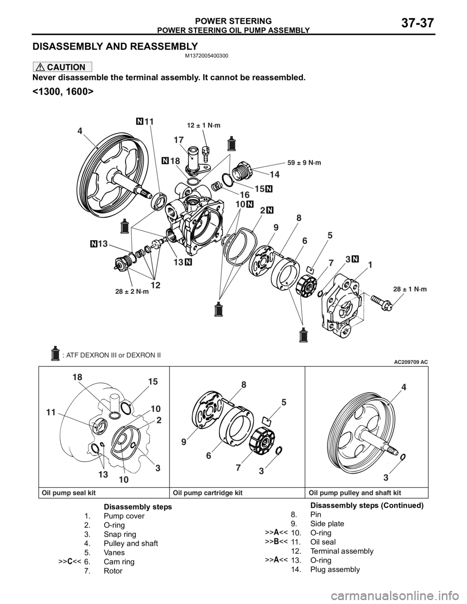
POWER STEERING OIL PUMP ASSEMBLY
POWER STEERING37-37
DISASSEMBLY AND REASSEMBLY
M1372005400300
CAUTION
Never disassemble the terminal assembly. It cannot be reassembled.
<1300, 1600>
AC209709AC
411
13 18
102
9 8
6 5
7 3
1
18 15
10 2
11
1310 39 8
6 5
7 3 4
3
28 ± 1 N·m
16 1514
59 ± 9 N·m
1228 ± 2 N·m
17
12 ± 1 N·m
13
Oil pump seal kit Oil pump cartridge kit Oil pump pulley and shaft kit : ATF DEXRON III or DEXRON II
Disassembly steps
1.Pump cover
2.O-ring
3.Snap ring
4.Pulley and shaft
5.Va n e s
>>C<<6.Cam ring
7.Rotor
8.Pin
9.Side plate
>>A<<10.O-ring
>>B<<11 .Oil seal
12.Terminal assembly
>>A<<13.O-ring
14.Plug assembly
Disassembly steps (Continued)
Page 268 of 800
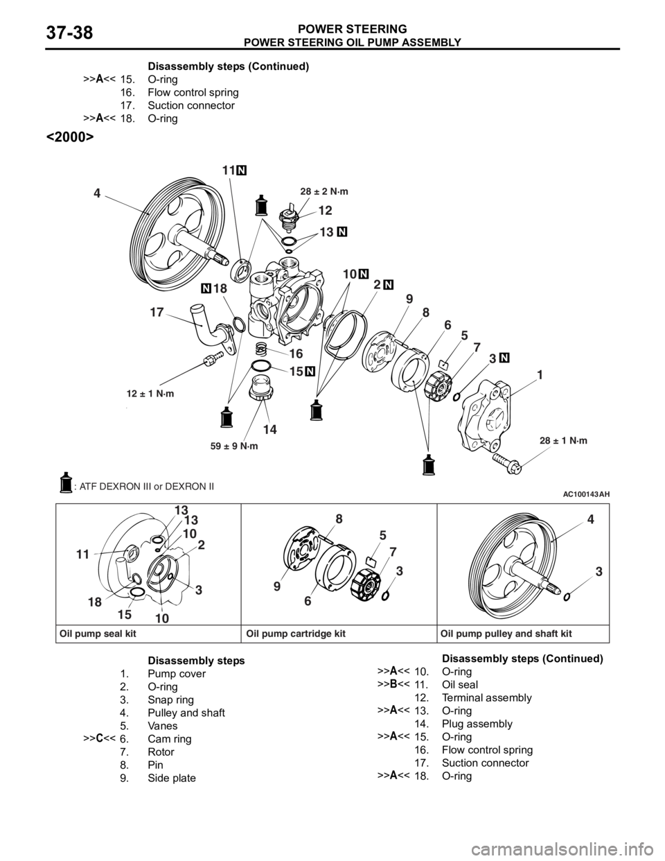
POWER STEERING OIL PUMP ASSEMBLY
POWER STEERING37-38
<2000>
AC100143AH
4 11
12
13
28 ± 2 N·m
102
9 8 65
7 3
1
28 ± 1 N·m
15
16
14
59 ± 9 N·m
12 ± 1 N·m
18
17
57
3
9 8
6
3
13
10 2
13
10
15
18
11
4
3
Oil pump seal kit Oil pump cartridge kit Oil pump pulley and shaft kit
: ATF DEXRON III or DEXRON II
Disassembly steps
1.Pump cover
2.O-ring
3.Snap ring
4.Pulley and shaft
5.Va n e s
>>C<<6.Cam ring
7.Rotor
8.Pin
9.Side plate
>>A<<10.O-ring
>>B<<11 .Oil seal
12.Terminal assembly
>>A<<13.O-ring
14.Plug assembly
>>A<<15.O-ring
16.Flow control spring
17.Suction connector
>>A<<18.O-ring
>>A<<15.O- rin g
16.Fl ow co n t ro l s p r i ng
17.Suction connector
>>A<<18.O-rin g
Disass embly st ep s ( C ont inu e d)
Disassembly steps (Continued)