gear MITSUBISHI LANCER 2006 Workshop Manual
[x] Cancel search | Manufacturer: MITSUBISHI, Model Year: 2006, Model line: LANCER, Model: MITSUBISHI LANCER 2006Pages: 800, PDF Size: 45.03 MB
Page 8 of 800

GENERAL INFORMATION
ENGINE LUBRICATION12-2
GENERAL INFORMATION
M1121000100357
The lubrication method is a fully force-fed, full-flow fil-
tration type. The engine oil pump is a trochoid type
which is driven by the crankshaft <4G1>.The engine
oil pump is a gear type which is driven by the crank
-
shaft via the balancer timing belt <4G6>.
ENGINE OILS
Health Warning
Prolonged and repeated contact with mineral oil will
result in the removal of natural fats from the skin,
leading to dryness, irritation and dermatitis. In addi
-
tion, used engine oil contains potentially harmful con-
taminants which may cause skin cancer. Adequate
means of skin protection and washing facilities must
be provided.
Recommended Precautions
The most effective precaution is to adapt working
practices which prevent, as far as practicable, the
risk of skin contact with mineral oils, for example by
using enclosed systems for handling used engine oil
and by degreasing components, where practicable,
before handling them. Other precautions:
•Avoid prolonged and repeated contact with oils,
particularly used engine oils.
•Wear protective clothing, including impervious
gloves where practicable.
•Avoid contaminating clothes, particularly under-
pants, with oil.
•Do not put oily rags in pockets, the use of overalls
without pockets will avoid this.
•Do not wear heavily soiled clothing and
oil-impregnated foot-wear. Overalls must be
cleaned regularly and kept separate from per
-
sonal clothing.
•Where there is a risk of eye contact, eye protec-
tion should be worn, for example, chemical gog-
gles or face shields; in addition an eye wash
facility should be provided.
•Obtain first aid treatment immediately for open
cuts and wounds.
•Wash regularly with soap and water to ensure all
oil is removed, especially before meals (skin
cleansers and nail brushes will help). After clean
-
ing, the application of preparations containing
lanolin to replace the natur al skin oils is advised.
•Do not use petrol, kerosine, diesel fuel, gas oil,
thinners or solvents for cleaning skin.
•Use barrier creams, applying them before each
work period, to help the removal of oil from the
skin after work.
•If skin disorders develop, obtain medical advice
without delay.
SERVICE SPECIFICATION
M1121000300232
ItemStandard value
Oil pressure kPaat idle29 or more
at 3,500 r/min294 − 686
LUBRICANT
M1121000400433
ItemSpecification
Engine oil ACEA classificationA1, A2 or A3
Engine oil API classificationSG or higher
Engine oil quantity L4G1Oil filter0.3
To t a l3.3
4G6Oil filter0.3
To t a l4.3
Page 81 of 800
STARTING SYSTEM
ENGINE ELECTRICAL16-19
STARTING SYSTEM
GENERAL INFORMATIONM1162000100202
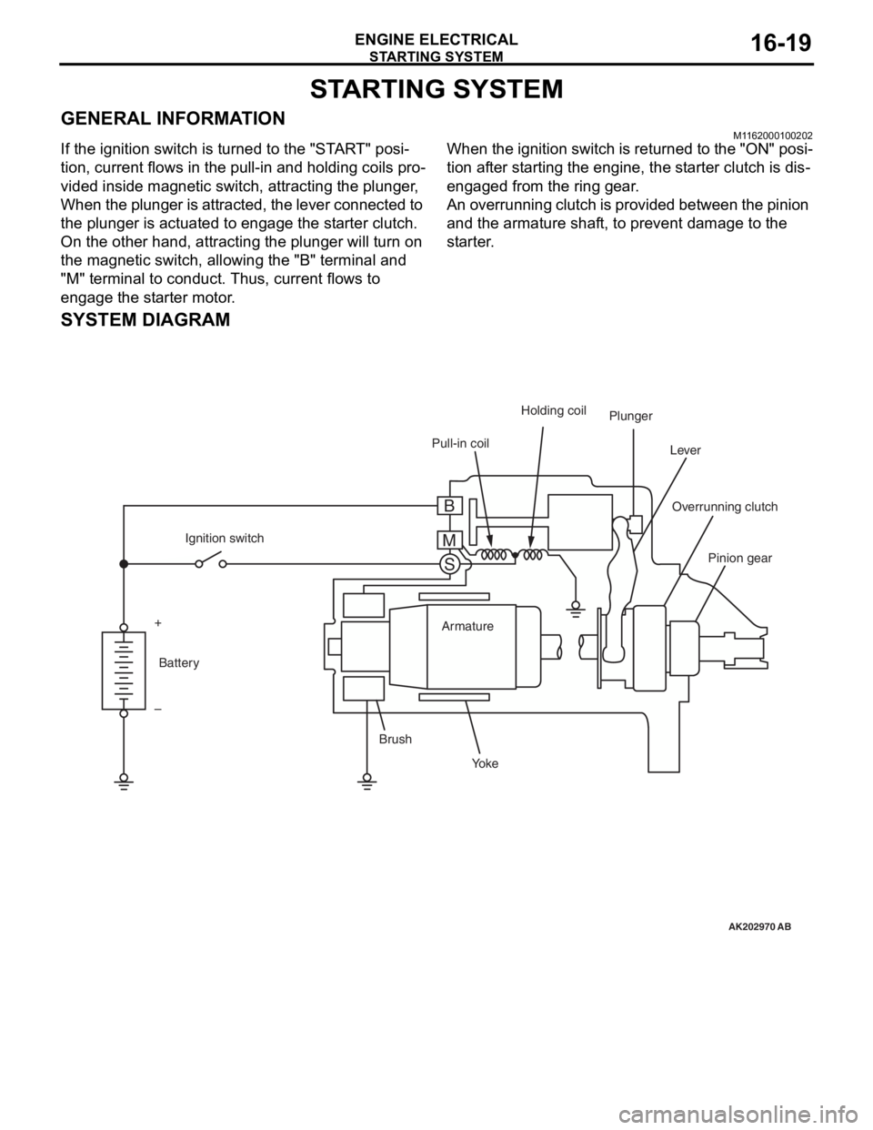
If the ignition switch is turned to the "START" posi-
tion, current flows in the pull-in and holding coils pro-
vided inside magnetic switch, attracting the plunger,
When the plunger is attracted, the lever connected to
the plunger is actuated to engage the starter clutch.
On the other hand, attracting the plunger will turn on
the magnetic switch, allowing the "B" terminal and
"M" terminal to conduct. Thus, current flows to
engage the starter motor.
When the ignition switch is returned to the "ON" posi-
tion after starting the engine, the starter clutch is dis-
engaged from the ring gear.
An overrunning clutch is provided between the pinion
and the armature shaft, to prevent damage to the
starter.
SYSTEM DIAGRAM
AK202970
Pull-in coilHolding coil
Plunger
Lever
Pinion gear
Overrunning clutch
Yo k e
Brush Armature
Ignition switch
Battery
+
–
AB
B
M S
Page 82 of 800

STARTING SYSTEM
ENGINE ELECTRICAL16-20
STARTER MOTOR SPECIFICATIONS
Item4G14G6
Ty p eReduction drive with planetary
gearReduction drive with planetary gear
Rated output kW/V1.2/121.4/12
Number of pinion teeth88
SERVICE SPECIFICATIONSM1162000300068
ItemStandard valueLimit
Pinion gap mm0.5 − 2.0−
Commutator run-out mm−0.05
Commutator diameter mm29.428.8
Undercut depth mm0.5 0.2
Page 88 of 800
STARTING SYSTEM
ENGINE ELECTRICAL16-26
DISASSEMBLY AND REASSEMBLY
M1162001200202
AK201881
141211
20
1
1516
17 18 19
13 10
2
43
5
7
6
8
9
AG
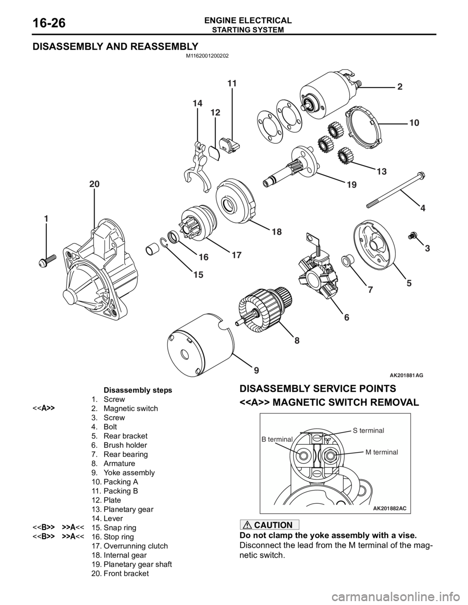
Disassembly steps
1.Screw
<>2.Magnetic switch
3.Screw
4.Bolt
5.Rear bracket
6.Brush holder
7.Rear bearing
8.Armature
9.Yoke assembly
10.Packing A
11 .Packing B
12.Plate
13.Planetary gear
14.Lever
<>>>A<<15.Snap ring
<>>>A<<16.Stop ring
17.Overrunning clutch
18.Internal gear
19.Planetary gear shaft
20.Front bracket
DISASSEMBL Y SER V ICE POINTS
<> MA GNETIC SW ITCH REM O V A L
AK201882
B terminal
M terminal
S terminal
AC
CAUTION
Do not clamp the yoke assembly with a vise.
Disconnect the lead from the M terminal of the mag-
netic switch.
Page 89 of 800
STARTING SYSTEM
ENGINE ELECTRICAL16-27
<> SNAP RING/STOP RING REMOVAL
AK100883AC
Socket wrench
Stop ring Pinion Gear
Overrunning
clutch
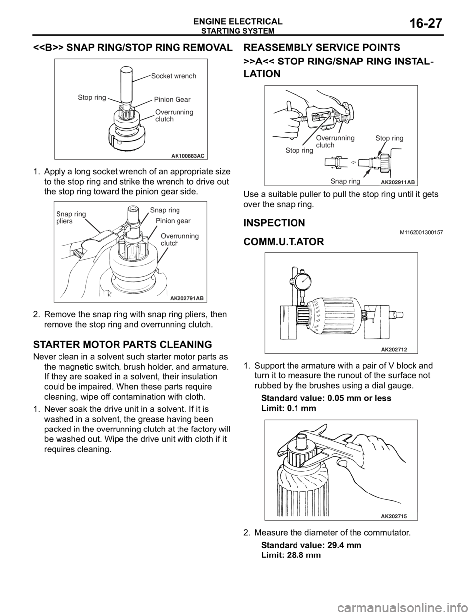
1. Ap ply a lo ng socket wr ench o f a n ap pro p ria t e size
to the stop ring and strike th e wrench to drive out
th e sto p ring toward th e pin i on g ear side.
AK202791
Snap ring
pliersSnap ring
Pinion gear
Overrunning
clutch
AB
2. Remove the snap ring with sna p ring pliers, th en
remove the stop ring an d overrunning clutch.
STARTER MOT O R P ARTS CLEANING
Never clean in a solvent such st arte r moto r p a rt s as
th e ma gnetic switch, brush hold e r , and arma ture.
If they are soake d in a solven t, their insulat i on
could be imp a ire d . When these p a rt s requ ire
clean ing, wipe of f co nt a m in ation with cloth .
1.Never so ak th e drive un it in a solve n t. If it is
washed in a solvent, th e grea se ha vin g been
p a cke d in th e over run n ing clutch at t he fa ct or y will
be washe d out. Wipe t he drive u n it with cloth if it
req u ires cleaning.
REASSEM BL Y SER V ICE POINT S
>>A<< STOP RING/SNAP RING INST AL-
LATION
AK202911
Overrunning
clutch Stop ring
Snap ring
Stop ring
AB
Use a suit
able puller to pull the stop ring u n til it ge t s
over t
he snap ring.
INSPECTION
M1162 0013 0015 7
COMM.U.T .A T O R
AK202712
1.Sup port the arma ture with a p a ir o f V block a nd
tu rn it t o mea s ure the run out of the surface not
ru bbed b y the brushes u s in g a dial g auge.
St andard va lue: 0.0 5 mm o r l ess
Limit: 0.1 mm
AK202715
2.Measure the diameter o f the commut ator .
St andard va lue: 29 .4 mm
Limit: 28.8 mm
Page 92 of 800
IGNITION SYSTEM
ENGINE ELECTRICAL16-30
IGNITION SYSTEM
GENERAL INFORMATIONM1163000100294
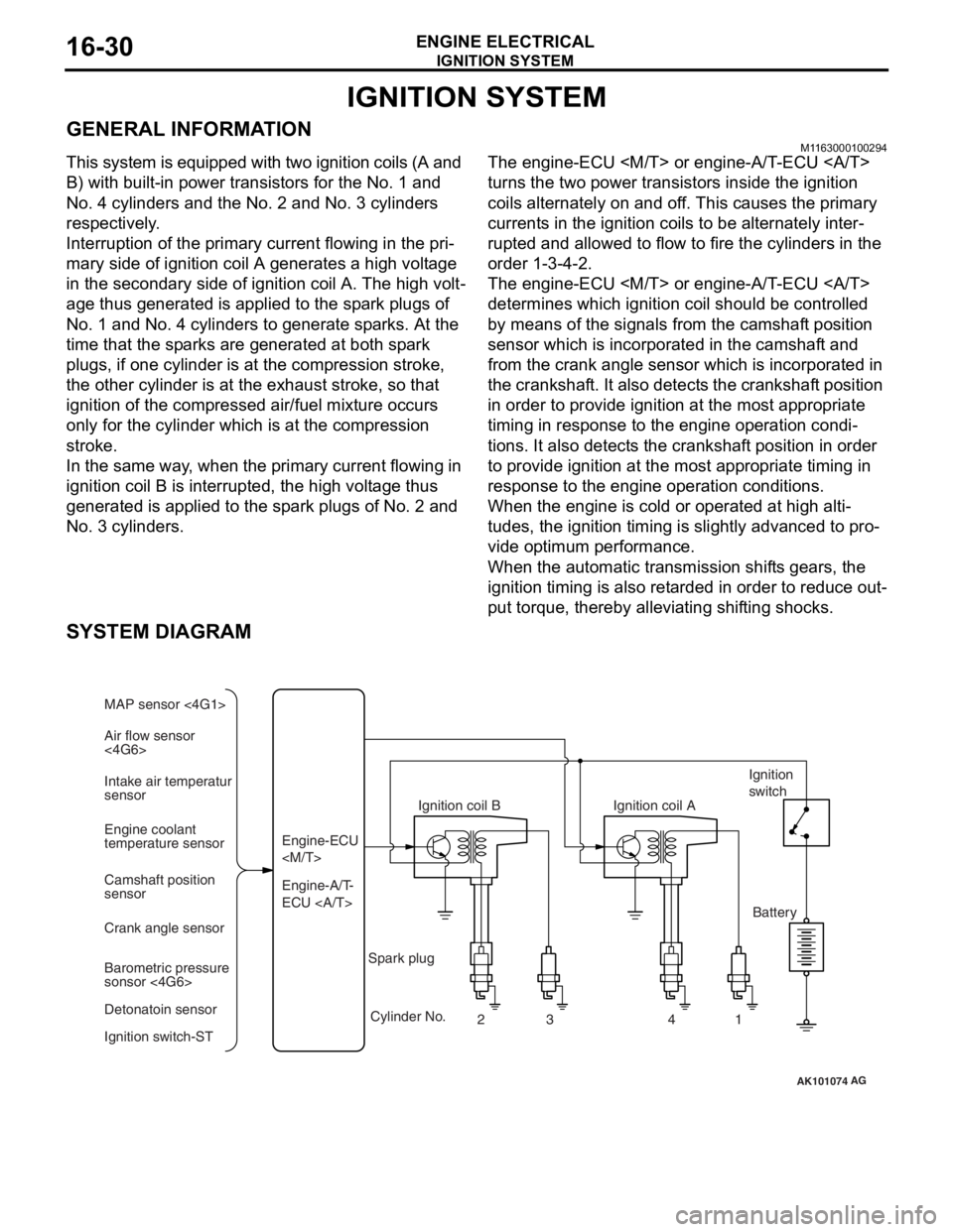
This system is equipped with two ignition coils (A and
B) with built-in power transistors for the No. 1 and
No. 4 cylinders and the No. 2 and No. 3 cylinders
respectively.
Interruption of the primary current flowing in the pri-
mary side of ignition coil A generates a high voltage
in the secondary side of ignition coil A. The high volt
-
age thus generated is applied to the spark plugs of
No. 1 and No. 4 cylinders to generate sparks. At the
time that the sparks are generated at both spark
plugs, if one cylinder is at the compression stroke,
the other cylinder is at the exhaust stroke, so that
ignition of the compressed air/fuel mixture occurs
only for the cylinder which is at the compression
stroke.
In the same way, when the primary current flowing in
ignition coil B is interrupted, the high voltage thus
generated is applied to the spark plugs of No. 2 and
No. 3 cylinders.
The engine-ECU
turns the two power transistors inside the ignition
coils alternately on and off. This causes the primary
currents in the ignition coils to be alternately inter
-
rupted and allowed to flow to fire the cylinders in the
order 1-3-4-2.
The engine-ECU
determines which ignition coil should be controlled
by means of the signals from the camshaft position
sensor which is incorporated in the camshaft and
from the crank angle sensor which is incorporated in
the crankshaft. It also detects the crankshaft position
in order to provide ignition at the most appropriate
timing in response to the engine operation condi
-
tions. It also detects the crankshaft position in order
to provide ignition at the most appropriate timing in
response to the engine operation conditions.
When the engine is cold or operated at high alti-
tudes, the ignition timing is slightly advanced to pro-
vide optimum performance.
When the automatic transmission shifts gears, the
ignition timing is also retarded in order to reduce out
-
put torque, thereby alleviating shifting shocks.
SYSTEM DIAGRAM
AK101074
Air flow sensor
<4G6> MAP sensor <4G1>
Intake air temperatur
sensor
Engine coolant
temperature sensor
Camshaft position
sensor
Crank angle sensor
Barometric pressure
sonsor <4G6>
Detonatoin sensor
Ignition switch-ST Engine-A/T-
ECU Engine-ECU
Ignition coil B
Cylinder No. 23 4
AG
1
Spark plug Ignition coil A
Ignition
switch
Battery
Page 134 of 800
GENERAL INFORMATION
FRONT AXLE26-2
GENERAL INFORMATION
M1261000100648
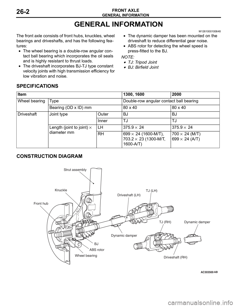
The front axle consists of front hubs, knuckles, wheel
bearings and driveshafts, and has the following fea
-
tures:
•The wheel bearing is a double-row angular con-
tact ball bearing which incorporates the oil seals
and is highly resistant to thrust loads.
•The driveshaft incorporates BJ-TJ type constant
velocity joints with high transmission efficiency for
low vibration and noise.
•The dynamic damper has been mounted on the
driveshaft to reduce differential gear noise.
•ABS rotor for detecting the wheel speed is
press-fitted to the BJ.
NOTE: .
•TJ: Tripod Joint
•BJ: Birfield Joint
SPECIFICATIONS
Item1300, 16002000
Wheel bearingTy p eDouble-row angular contact ball bearing
Bearing (OD x ID) mm80 x 4080 x 40
DriveshaftJoint typeOuterBJBJ
InnerTJTJ
Length (joint to joint) ×
diameter mm LH 375.9 × 24 375.9 × 24
RH699 × 24 (1600-M/T),
703.2
× 23 (1300-M/T,
1600-A/T)
700 × 24 (M/T)
699 × 24 (A/T)
CONSTRUCTION DIAGRAM
AC303569
Front hub KnuckleStrut assembly
TJ (LH)
Driveshaft (LH)
Dynamic damper
BJ
Wheel bearing Driveshaft (RH)
TJ (RH)
AB
ABS rotor
Dynamic damper
Page 179 of 800
CROSSMEMBER
POWER PLANT MOUNT32-9
AC304000
108 ± 10 N·m25 ± 4 N·m 18 ± 2 N·m
70 ± 10 N·m
21 ± 4 N·m
21 ± 4 N·m
186 ± 10 N·m* 167 ± 9 N·m49 ± 10 N·m
52 ± 7 N·m* 45 ± 5 N·m*
70 ± 10 N·m
57 ± 7 N·m
12 ± 2 N·m
5
4
10
9
11
8
12
1413
6
7 16
15
17 2
3
1
N
N
N
2
1 1
AB
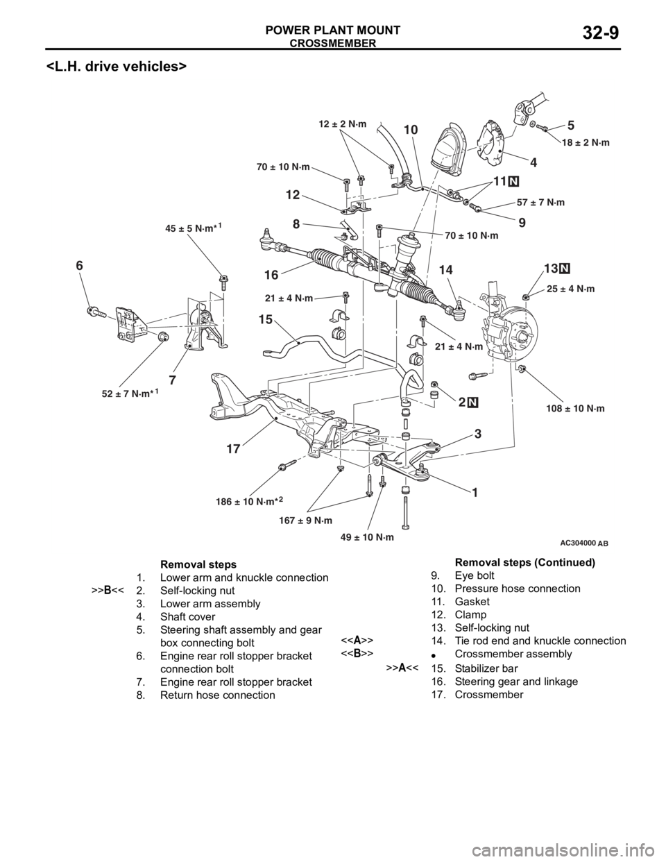
Removal steps
1.Lower arm and knuckle connection
>>B<<2.Self-locking nut
3.Lower arm assembly
4.Shaft cover
5.Steering shaft assembly and gear
box connecting bolt
6.Engine rear roll stopper bracket
connection bolt
7.Engine rear roll stopper bracket
8.Return hose connection
9.Eye bolt
10.Pressure hose connection
11 .Gasket
12.Clamp
13.Self-locking nut
<>14.Tie rod end and knuckle connection
<>•Crossmember assembly
>>A<<15.Stabilizer bar
16.Steering gear and linkage
17.Crossmember
Removal steps (Continued)
Page 180 of 800
CROSSMEMBER
POWER PLANT MOUNT32-10
AC101614
12
3
4
5
6 7
8
9
10
11
12
13 14
15
16
45 ± 5 N·m*¹
52 ± 7 N·m*¹ 186 ± 10 N·m*²167 ± 9 N·m
49 ± 10 N·m 108 ± 10 N·m25 ± 4 N·m
21 ± 4 N·m 70 ± 10 N·m
5.0 ± 1.0 N·m
18 ± 2 N·m
57 ± 7 N·m
N
N
N
AE
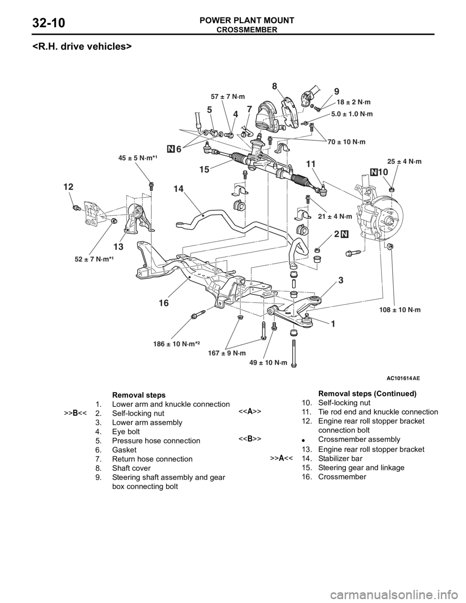
Removal steps
1.Lower arm and knuckle connection
>>B<<2.Self-locking nut
3.Lower arm assembly
4.Eye bolt
5.Pressure hose connection
6.Gasket
7.Return hose connection
8.Shaft cover
9.Steering shaft assembly and gear
box connecting bolt
10.Self-locking nut
<>11 .Tie rod end and knuckle connection
12.Engine rear roll stopper bracket
connection bolt
<>•Crossmember assembly
13.Engine rear roll stopper bracket
>>A<<14.Stabilizer bar
15.Steering gear and linkage
16.Crossmember
Removal steps (Continued)
Page 181 of 800
