ron MITSUBISHI LANCER 2006 Workshop Manual
[x] Cancel search | Manufacturer: MITSUBISHI, Model Year: 2006, Model line: LANCER, Model: MITSUBISHI LANCER 2006Pages: 800, PDF Size: 45.03 MB
Page 55 of 800
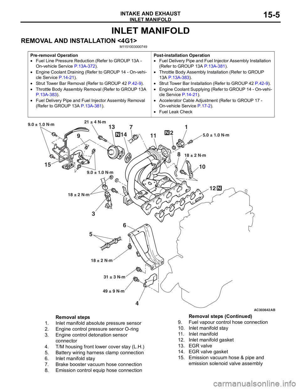
INLET MANIFOLD
INTAKE AND EXHAUST15-5
INLET MANIFOLD
REMOVAL AND INSTALLATION <4G1>M1151003000749
Pre-removal Operation
•Fuel Line Pressure Reduction (Refer to GROUP 13A -
On-vehicle Service
P.13A-372).
•Engine Coolant Draining (Refer to GROUP 14 - On-vehi-
cle Service P.14-21).
•Strut Tower Bar Removal (Refer to GROUP 42 P.42-9).
•Throttle Body Assembly Re moval (Refer to GROUP 13A
P.13A-383).
•Fuel Delivery Pipe and Fuel Injector Assembly Removal
(Refer to GROUP 13A
P.13A-381).
Post-installation Operation
•Fuel Delivery Pipe and Fuel Injector Assembly Installation
(Refer to GROUP 13A
P.13A-381).
•Throttle Body Assembly Inst allation (Refer to GROUP
13A
P.13A-383).
•Strut Tower Bar Installati on (Refer to GROUP 42 P.42-9).
•Engine Coolant Supplying (Refer to GROUP 14 - On-vehi-
cle Service P.14-21).
•Accelerator Cable Adjustment (Refer to GROUP 17 -
On-vehicle Service
P.17-2).
•Fuel Leak Check
AC303642AB
15
36
5
4 12
10
7
1
2
11
9 13
14
21 ± 4 N·m
9.0 ± 1.0 N·m
9.0 ± 1.0 N·m
18 ± 2 N·m
18 ± 2 N·m 18 ± 2 N·m
5.0 ± 1.0 N·m
31 ± 3 N·m
49 ± 9 N·m
N
N
N
8
Removal steps
1.Inlet manifold absolute pressure sensor
2.Engine control pressure sensor O-ring
3.Engine control detonation sensor
connector
4.T/M housing front lower cover stay (L.H.)
5.Battery wiring harness clamp connection
6.Inlet manifold stay
7.Brake booster vacuum hose connection
8.Emission control equip hose connection
9.Fuel vapour control hose connection
10.Inlet manifold stay
11 .Inlet manifold
12.Inlet manifold gasket
13.EGR valve
14.EGR valve gasket
15.Emission vacuum hose & pipe and
emission solenoid valve assembly
Removal steps (Continued)
Page 58 of 800
Removal steps
1.Front exhaust pipe connection
2.Exhaust pipe gasket
<>>>A<<3.Engine control oxygen sensor (front)
4.Engine oil level gauge and guide
assembly
5.Engine oil filler O-ring
6.Exhaust manifold cover
7.Exhaust manifold bracket
8.Exhaust manifold
9.Exhaust manifold gasket
EXHAUST MANIFOLD
INTAKE AND EXHAUST15-8
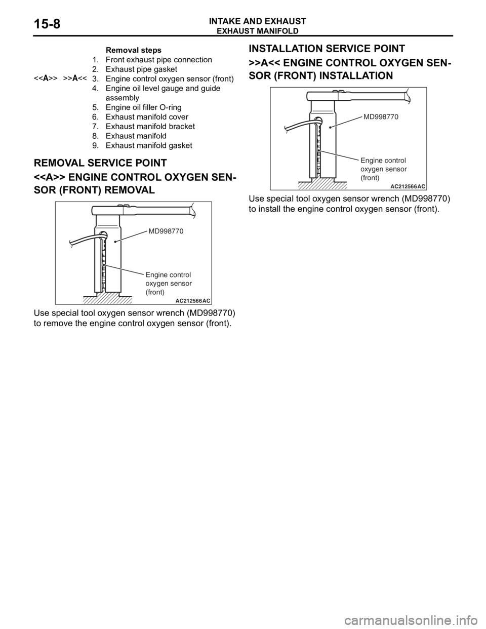
REMOVAL SERVICE POINT
<> ENGINE CONTROL OXYGEN SEN-
SOR (FRONT) REMOVAL
AC212566AC
MD998770
Engine control
oxygen sensor
(front)
Use spe c ia l tool oxyg en sen s or wrench (MD9987 70)
to remove t
he eng ine contro l oxygen sen s or (fro nt).
INSTALLA T ION SER VICE POINT
>>A<< ENGINE CONT ROL OXYGEN SEN-
SOR (FRONT) INSTALLA TION
AC212566AC
MD998770
Engine control
oxygen sensor
(front)
Use spe c ia l tool oxyg en sen s or wrench (MD9987 70)
to inst
all the eng ine contro l oxyge n sen s or (f ront).
Page 59 of 800
EXHAUST MANIFOLD
INTAKE AND EXHAUST15-9
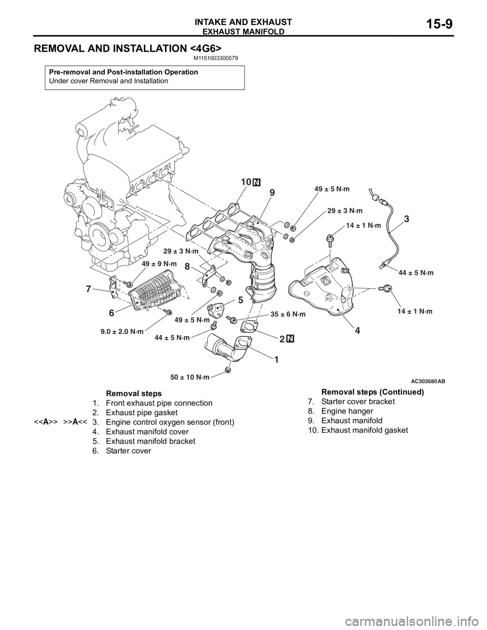
REMOVAL AND INSTALLATION <4G6>
M1151003300579
Pre-removal and Post-installation Operation
Under cover Removal and Installation
AC30368050 ± 10 N·m
44 ± 5 N·m
35 ± 6 N·m14 ± 1 N·m
14 ± 1 N·m
49 ± 5 N·m 29 ± 3 N·m
29 ± 3 N·m
N
3
4
1 2
5
N
8 944 ± 5 N·m
AB
1049 ± 5 N·m
6
7
9.0 ± 2.0 N·m 49 ± 9 N·m
Removal steps
1.Front exhaust pipe connection
2.Exhaust pipe gasket
<>>>A<<3.Engine control oxygen sensor (front)
4.Exhaust manifold cover
5.Exhaust manifold bracket
6.Starter cover
7.Starter cover bracket
8.Engine hanger
9.Exhaust manifold
10.Exhaust manifold gasket
Removal steps (Continued)
Page 60 of 800
Page 61 of 800
AC303695AC
1
3
50 ± 10 N·m
2
7
N
N
45
8 4
N9
10
59 ± 10 N·m
45 ± 5 N·m
13 ± 2 N·m
45 ± 5 N·m
13 ± 2 N·m
10
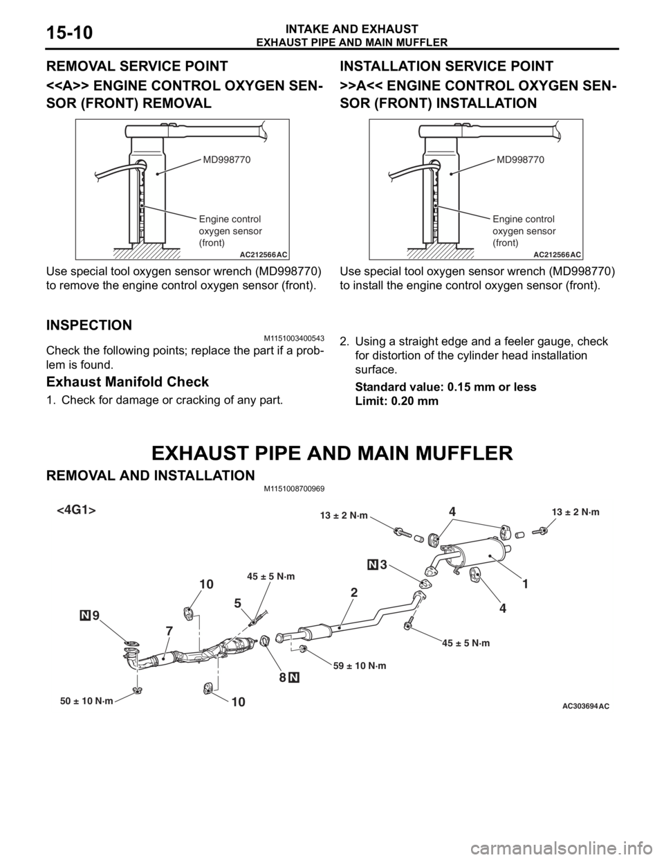
<4G6-M/T>
AC504798AB
<4G6-A/T> 1
2
3N
4
7N8
N9
10
13 ± 2 N·m
13 ± 2 N·m
45 ± 5 N·m
59 ± 10 N·m
6N
10
4
50 ± 10 N·m
13 ± 2 N·m
13 ± 2 N·m
50 ± 10 N·m
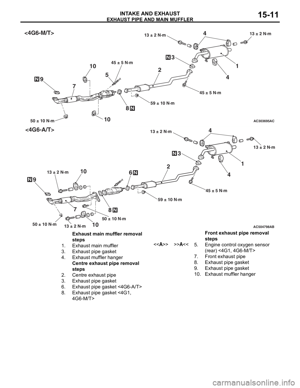
Exhaust main muffler removal
steps
1.Exhaust main muffler
3.Exhaust pipe gasket
4.Exhaust muffler hanger
Centre exhaust pipe removal
steps
2.Centre exhaust pipe
3.Exhaust pipe gasket
6.Exhaust pipe gasket <4G6-A/T>
8.Exhaust pipe gasket <4G1,
4G6-M/T>
Front exhaust pipe removal
steps
<>>>A<<5.Engine control oxygen sensor
(rear) <4G1, 4G6-M/T>
7.Front exhaust pipe
8.Exhaust pipe gasket
9.Exhaust pipe gasket
10.Exhaust muffler hanger
EX HAUS T PIPE AND MAIN MU FFLER
INTAKE AN D EXHAU ST15-11
Page 64 of 800
CHARGING SYSTEM
ENGINE ELECTRICAL16-2
CHARGING SYSTEM
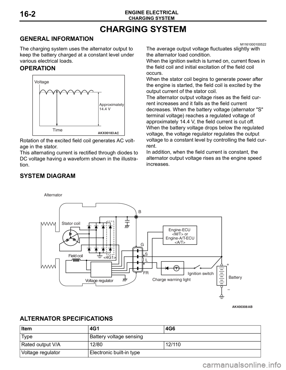
GENERAL INFORMATIONM1161000100522
The charging system uses the alternator output to
keep the battery charged at a constant level under
various electrical loads.
OPERATION
AKX00183
VoltageTime
Approximately
14.4 V
AC
Rota tion of the excited fi eld coil gene rates AC volt-
age in the sta t or .
This alternatin g cur r ent is rectified throu gh diodes to
DC volt
age h a ving a waveform sh own in t he illustra
-
tion.
The average outpu t volt a ge flu c tua t es slightly with
the alternato
r load con d ition.
When the ign i tion switch is t u rned on, current flows in
the field coil and initial e
x cit a tion of the field coil
occurs.
When the st ator coil beg ins to gen erate p o wer af ter
the eng
ine is st a r ted, th e fie l d coil is excited by th e
output
curren t of th e st ator coil.
The alternator outpu t volt a ge rises as th e fie l d cur-
rent increa ses and it falls a s the field cu rrent
decre
ases. Whe n the b a ttery volt a ge (alternato r "S"
terminal volt
ag e) reaches a regulated volt ag e of
approximately 14.4
V , the field current is cut o f f.
When th
e batte ry volt age drop s be low the regulated
volt
ag e, the volt ag e regulator re gulat es th e outp u t
volt
ag e to a const ant level by contro lling the field cur
-
rent.
In addition, when th e fie l d current is const a n t, the
altern
ator ou tput volt age rise s as the e ngine spe ed
increase
s .
SYSTEM DIAGRAM
AK400308
Alternator
B
Stator coil
Engine-ECU
Engine-A/T-ECU
G
SL
FR
<4G1>
Voltage regulator Charge warning lightIgnition switch
Battery
Field coil
+
–
AB
AL TERNA T O R SPECIFICA T IONS
Item4G14G6
Ty p eBattery voltage sensing
Rated output V/A12/8012/110
Voltage regulatorElectronic built-in type
Page 77 of 800
CHARGING SYSTEM
ENGINE ELECTRICAL16-15
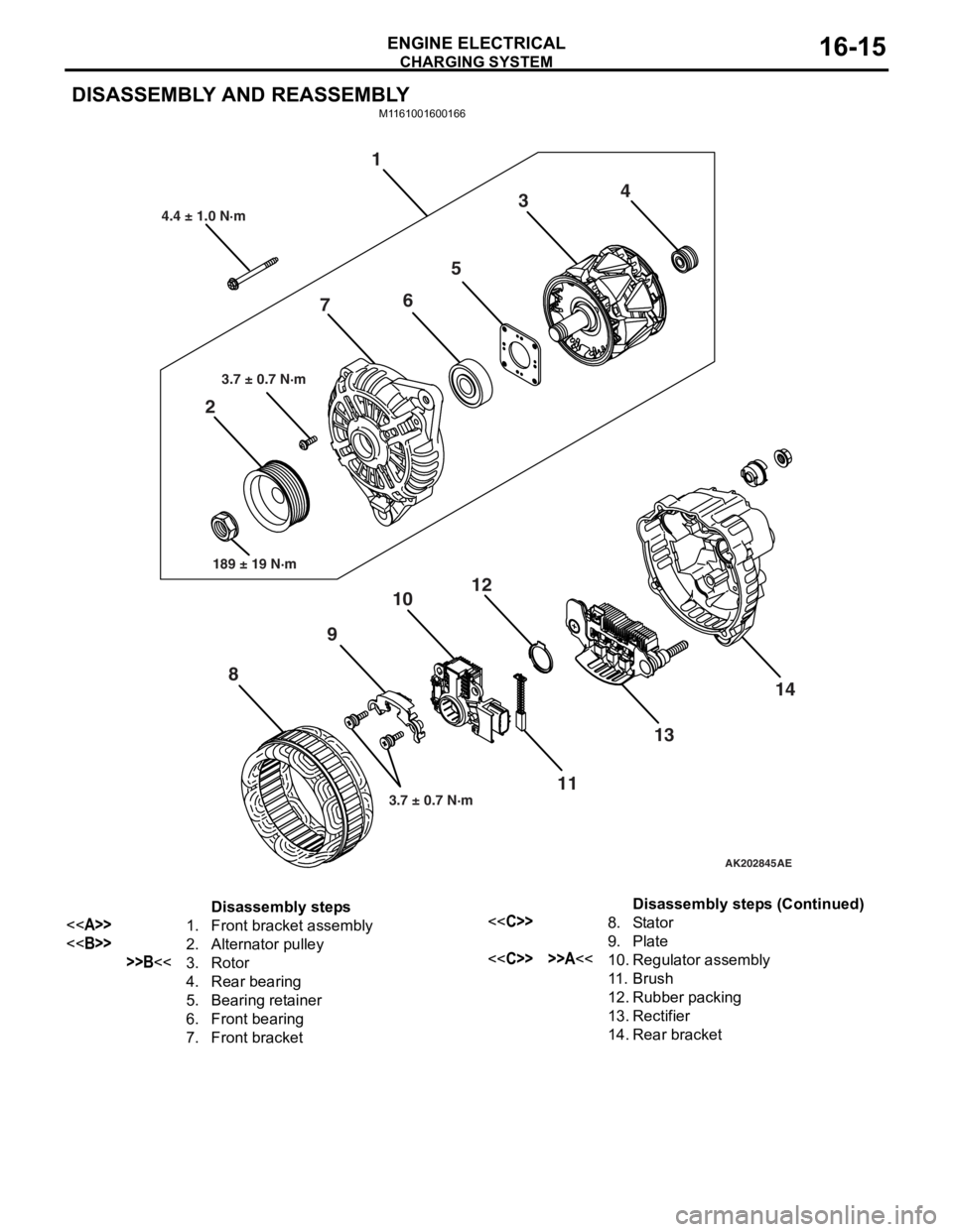
DISASSEMBLY AND REASSEMBLY
M1161001600166
AK202845
1
2 3
4
5
6
7
8 9
10
11
12
1314
AE
4.4 ± 1.0 N·m
3.7 ± 0.7 N·m
189 ± 19 N·m
3.7 ± 0.7 N·m
Disassembly steps
<>1.Front bracket assembly
<>2.Alternator pulley
>>B<<3.Rotor
4.Rear bearing
5.Bearing retainer
6.Front bearing
7.Front bracket
<
9.Plate
<
11 .Brush
12.Rubber packing
13.Rectifier
14.Rear bracket
Disassembly steps (Continued)
Page 78 of 800
Page 85 of 800
STARTING SYSTEM
ENGINE ELECTRICAL16-23
STARTER MOTOR ASSEMBLY INSPECTION
M1162001100205
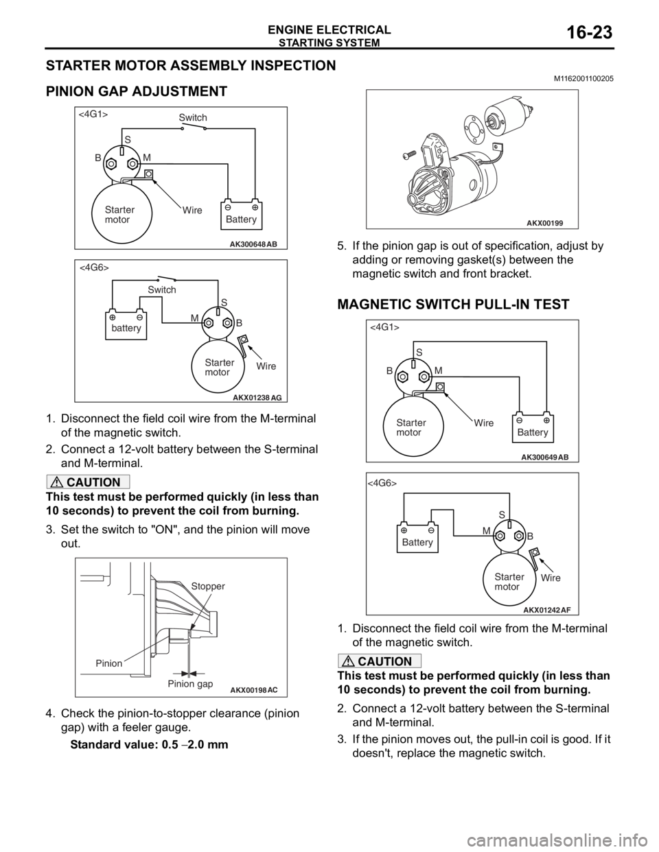
PINION GAP ADJUSTMENT
AK300648AB
<4G1>
Switch
S M
Wire Battery
Starter
motor
B
AKX01238
<4G6>
B
M S
battery Switch
Starter
motorWire
AG
1.
Disco nnect the field coil wire f r om th e M-te rmin al
of the magnet ic switch.
2.Conn ect a 12-volt b a ttery between the S-termina l
an d M-t e rminal.
CAUTION
This test must be performed quickly (in less than
10 seconds) to prevent the coil from burning.
3. Set the switch to "ON", and the pinion will move out.
AKX00198
Stopper
Pinion gap
Pinion
AC
4. Check the pinion-to-stopper clearance (pinion
gap) with a feeler gauge.
Standard value: 0.5 − 2.0 mm
AKX00199
5. If the pinion gap is out of specification, adjust by adding or removing gasket(s) between the
magnetic switch and front bracket.
MAGNETIC SWITCH PULL-IN TEST
AK300649AB
<4G1>
SM
Wire Battery
Starter
motor
B
AKX01242
<4G6>
SB
M
Battery
Starter
motorWire
AF
1. Disconnect the field coil wire from the M-terminal
of the magnetic switch.
CAUTION
This test must be performed quickly (in less than
10 seconds) to prevent the coil from burning.
2. Connect a 12-volt battery between the S-terminal and M-terminal.
3. If the pinion moves out, the pull-in coil is good. If it doesn't, replace the magnetic switch.
Page 88 of 800
STARTING SYSTEM
ENGINE ELECTRICAL16-26
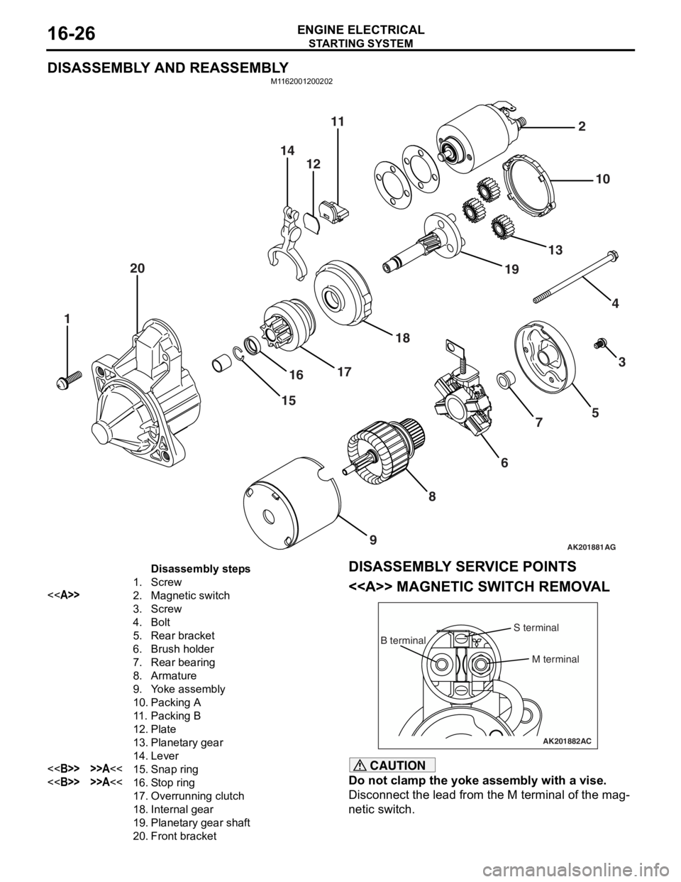
DISASSEMBLY AND REASSEMBLY
M1162001200202
AK201881
141211
20
1
1516
17 18 19
13 10
2
43
5
7
6
8
9
AG
Disassembly steps
1.Screw
<>2.Magnetic switch
3.Screw
4.Bolt
5.Rear bracket
6.Brush holder
7.Rear bearing
8.Armature
9.Yoke assembly
10.Packing A
11 .Packing B
12.Plate
13.Planetary gear
14.Lever
<>>>A<<15.Snap ring
<>>>A<<16.Stop ring
17.Overrunning clutch
18.Internal gear
19.Planetary gear shaft
20.Front bracket
DISASSEMBL Y SER V ICE POINTS
<> MA GNETIC SW ITCH REM O V A L
AK201882
B terminal
M terminal
S terminal
AC
CAUTION
Do not clamp the yoke assembly with a vise.
Disconnect the lead from the M terminal of the mag-
netic switch.