service MITSUBISHI LANCER 2006 Owner's Manual
[x] Cancel search | Manufacturer: MITSUBISHI, Model Year: 2006, Model line: LANCER, Model: MITSUBISHI LANCER 2006Pages: 800, PDF Size: 45.03 MB
Page 63 of 800
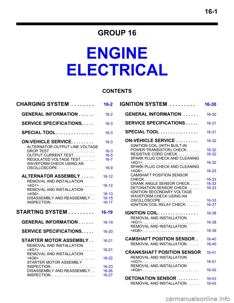
16-1
GROUP 16
ENGINE
ELECTRICAL
CONTENTS
CHARGING SYSTEM . . . . . . . .16-2
GENERAL INFORMATION . . . . . .16-2
SERVICE SPECIFICATIONS. . . . .16-3
SPECIAL TOOL . . . . . . . . . . . . . . .16-3
ON-VEHICLE SERVICE. . . . . . . . .16-3
ALTERNATOR OUTPUT LINE VOLTAGE
DROP TEST . . . . . . . . . . . . . . . . . . . . . 16-3
OUTPUT CURRENT TEST . . . . . . . . . . 16-5
REGULATED VOLTAGE TEST . . . . . . . 16-7
WAVEFORM CHECK USING AN
OSCILLOSCOPE . . . . . . . . . . . . . . . . . . 16-9
ALTERNATOR ASSEMB LY . . . . .16-12
REMOVAL AND INSTALLATION
<4G1> . . . . . . . . . . . . . . . . . . . . . . . . . . 16-12
REMOVAL AND INSTALLATION
<4G6> . . . . . . . . . . . . . . . . . . . . . . . . . . 16-13
DISASSEMBLY AND REASSEMBLY . . 16-15
INSPECTION . . . . . . . . . . . . . . . . . . . . . 16-17
STARTING SYSTEM . . . . . . . . .16-19
GENERAL INFORMATION . . . . . .16-19
SERVICE SPECIFICATIONS. . . . .16-20
STARTER MOTOR ASSEMBLY . .16-21
REMOVAL AND INSTALLATION
<4G1> . . . . . . . . . . . . . . . . . . . . . . . . . . 16-21
REMOVAL AND INSTALLATION
<4G6> . . . . . . . . . . . . . . . . . . . . . . . . . . 16-22
STARTER MOTOR ASSEMBLY
INSPECTION . . . . . . . . . . . . . . . . . . . . . 16-23
DISASSEMBLY AND REASSEMBLY . . 16-26
INSPECTION . . . . . . . . . . . . . . . . . . . . . 16-27
IGNITION SYSTEM . . . . . . . . . 16-30
GENERAL INFORMATION . . . . . .16-30
SERVICE SPECIFICATIONS . . . . .16-31
SPECIAL TOOL . . . . . . . . . . . . . . .16-31
ON-VEHICLE SERVICE . . . . . . . . .16-32
IGNITION COIL (WITH BUILT-IN
POWER TRANSISTOR) CHECK . . . . . . 16-32
RESISTIVE CORD CHECK . . . . . . . . . . 16-32
SPARK PLUG CHECK AND CLEANING
<4G1>. . . . . . . . . . . . . . . . . . . . . . . . . . . 16-32
SPARK PLUG CHECK AND CLEANING
<4G6>. . . . . . . . . . . . . . . . . . . . . . . . . . . 16-33
CAMSHAFT POSITION SENSOR
CHECK . . . . . . . . . . . . . . . . . . . . . . . . . . 16-33
CRANK ANGLE SENSOR CHECK . . . . 16-33
DETONATION SENSOR CHECK . . . . . 16-33
IGNITION SECONDARY VOLTAGE
WAVEFORM CHECK USING AN
OSCILLOSCOPE . . . . . . . . . . . . . . . . . . 16-33
IGNITION COIL RELAY CHECK . . . . . . 16-37
IGNITION COIL . . . . . . . . . . . . . . . .16-38
REMOVAL AND INSTALLATION
<4G1>. . . . . . . . . . . . . . . . . . . . . . . . . . . 16-38
REMOVAL AND INSTALLATION
<4G6>. . . . . . . . . . . . . . . . . . . . . . . . . . . 16-39
CAMSHAFT POSITION SENSOR .16-40
REMOVAL AND INSTALLATION . . . . . . 16-40
CRANKSHAFT POSITION SENSOR16-41
REMOVAL AND INSTALLATION
<4G1>. . . . . . . . . . . . . . . . . . . . . . . . . . . 16-41
REMOVAL AND INSTALLATION
<4G6>. . . . . . . . . . . . . . . . . . . . . . . . . . . 16-42
DETONATION SENSOR . . . . . . . .16-43
REMOVAL AND INSTALLATION . . . . . . 16-43
Page 65 of 800
CHARGING SYSTEM
ENGINE ELECTRICAL16-3
SERVICE SPECIFICATIONS
M1161000300258
ItemStandard valueLimit
Alternator output line voltage drop (at 30 A) V−maximum 0.3
Regulated voltage ambient
temperature at voltage regulator V−20°C14.2 − 15.4−
20°C13.9 − 14.9−
60°C13.4 − 14.6−
80°C13.1 − 14.5−
Output current−70 % of normal output current
SPECIAL TOOLM1161000600163
ToolNumberNameUse
MB991519Alterna t or test harn e ssChec king th e alt e rnator
("S" te rminal volt age )
ON-VEHICLE SERV ICE
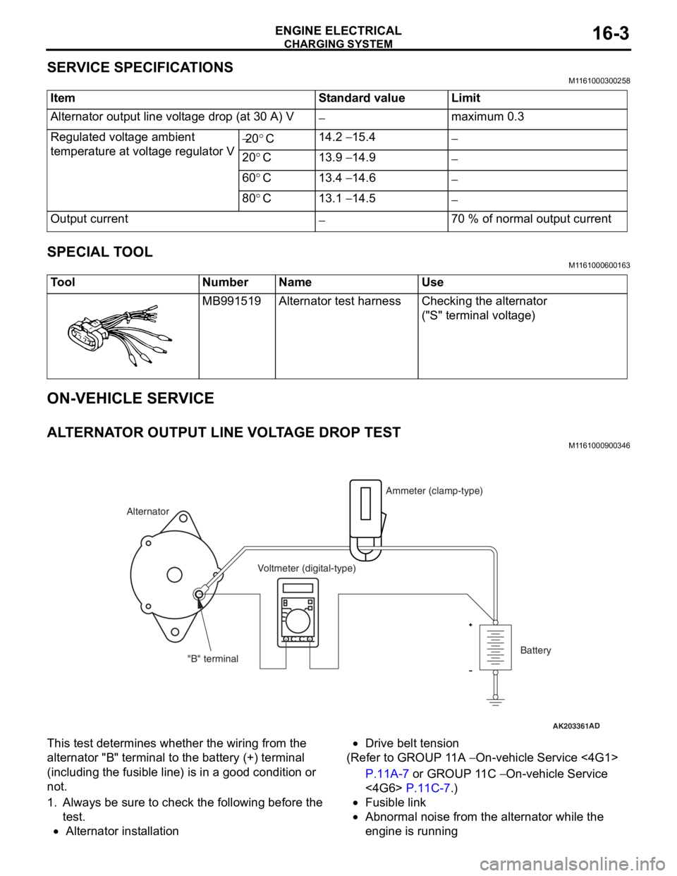
ALTERNA T O R OUTPUT LINE VOL T AGE DROP TEST
M1161 0009 0034 6
AK203361AD
Alternator Ammeter (clamp-type)
Voltmeter (digital-type)
"B" terminal Battery
This test
determine s whethe r the wiring fro m th e
altern
ator "B" termina l to t he batt e ry (+) terminal
(including the
fusible line ) is in a good condition or
not.
1.Always b e su re to check the following b e fore th e
te st.
•Alternator inst allatio n
•Drive belt tension
(Ref er to GROUP 1 1 A − On-veh icle Service <4G1>
P.11A-7 or GROUP 1 1 C − On-vehicle Service
<4G6> P.11C-7.)
•Fusible link
•Abnormal noise from the altern ator while the
eng
ine is ru nning
Page 66 of 800
CHARGING SYSTEM
ENGINE ELECTRICAL16-4
2. Turn the ignition switch to the "LOCK" (OFF)
position.
3. Disconnect the negative battery cable.
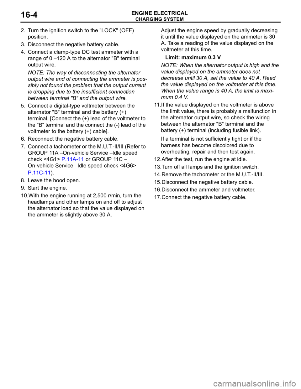
4. Connect a clamp-type DC test ammeter with a
range of 0
− 120 A to the alternator "B" terminal
output wire.
NOTE: The way of disconnecting the alternator
output wire and of connecting the ammeter is pos
-
sibly not found the problem that the output current
is dropping due to the insufficient connection
between terminal "B" and the output wire.
5. Connect a digital-type voltmeter between the
alternator "B" terminal and the battery (+)
terminal. [Connect the (+) lead of the voltmeter to
the "B" terminal and the connect the (-) lead of the
voltmeter to the battery (+) cable].
6. Reconnect the negative battery cable.
7. Connect a tachometer or the M.U.T.-II/III (Refer to
GROUP 11A
− On-vehicle Service − Idle speed
check <4G1>
P.11A-11 or GROUP 11C −
On-vehicle Service − Idle speed check <4G6>
P.11C-11).
8. Leave the hood open.
9. Start the engine.
10.With the engine running at 2,500 r/min, turn the
headlamps and other lamps on and off to adjust
the alternator load so that the value displayed on
the ammeter is slightly above 30 A.
Adjust the engine speed by gradually decreasing
it until the value displayed on the ammeter is 30
A. Take a reading of the value displayed on the
voltmeter at this time.
Limit: maximum 0.3 V
NOTE: When the alternator output is high and the
value displayed on the ammeter does not
decrease until 30 A, set the value to 40 A. Read
the value displayed on the voltmeter at this time.
When the value range is 40 A, the limit is maxi
-
mum 0.4 V.
11.If the value displayed on the voltmeter is above
the limit value, there is probably a malfunction in
the alternator output wire, so check the wiring
between the alternator "B" terminal and the
battery (+) terminal (including fusible link).
If a terminal is not sufficiently tight or if the
harness has become discolored due to
overheating, repair and then test again.
12.After the test, run the engine at idle.
13.Turn off all lamps and the ignition switch.
14.Remove the tachometer or the M.U.T.-II/III.
15.Disconnect the negative battery cable.
16.Disconnect the ammeter and voltmeter.
17.Connect the negative battery cable.
Page 67 of 800
Page 69 of 800
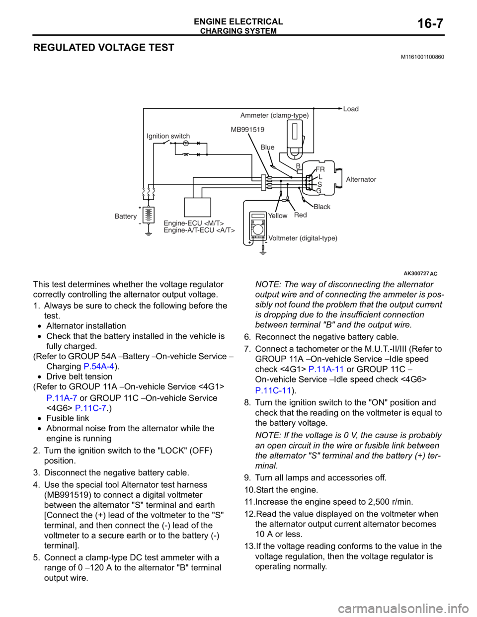
Page 74 of 800
CHARGING SYSTEM
ENGINE ELECTRICAL16-12
ALTERNATOR ASSEMBLY
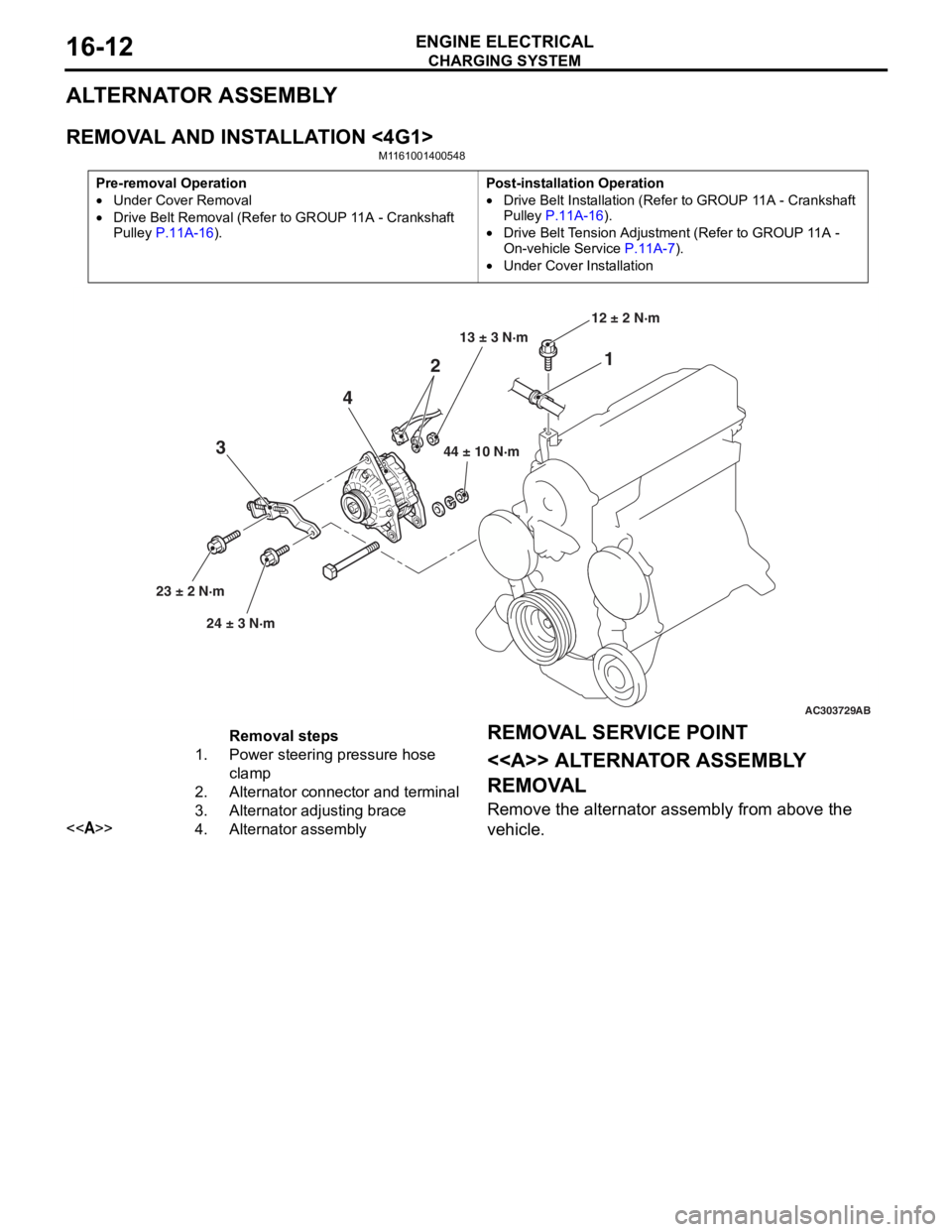
REMOVAL AND INSTALLATION <4G1>
M1161001400548
Pre-removal Operation
•Under Cover Removal
•Drive Belt Removal (Refer to GROUP 11A - Crankshaft
Pulley
P.11A-16).
Post-installation Operation
•Drive Belt Installation (Refer to GROUP 11A - Crankshaft
Pulley P.11A-16).
•Drive Belt Tension Adjustment (Refer to GROUP 11A -
On-vehicle Service P.11A-7).
•Under Cover Installation
AC303729
1
2
4
3
44 ± 10 N·m
23 ± 2 N·m 24 ± 3 N·m 12 ± 2 N·m
AB
13 ± 3 N·m
Removal steps
1.Power steering pressure hose
clamp
2.Alternator connector and terminal
3.Alternator adjusting brace
<>4.Alternator assembly
REMOV
A L SER VICE POINT
<> ALTERNA T O R ASSEMBL Y
REMOV
A L
Remove the a l tern ator assembly from above the
vehicle.
Page 75 of 800
CHARGING SYSTEM
ENGINE ELECTRICAL16-13
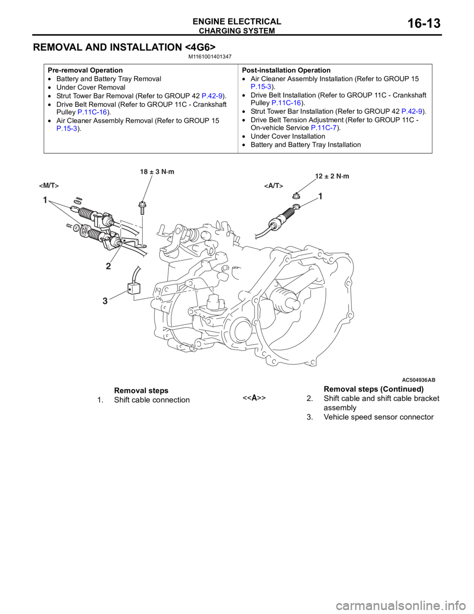
REMOVAL AND INSTALLATION <4G6>
M1161001401347
Pre-removal Operation
•Battery and Battery Tray Removal
•Under Cover Removal
•Strut Tower Bar Removal (Refer to GROUP 42 P.42-9).
•Drive Belt Removal (Refer to GROUP 11C - Crankshaft
Pulley P.11C-16).
•Air Cleaner Assembly Remo val (Refer to GROUP 15 P.15-3).
Post-installation Operation
•Air Cleaner Assembly Installation (Refer to GROUP 15 P.15-3).
•Drive Belt Installation (Refer to GROUP 11C - Crankshaft
Pulley P.11C-16).
•Strut Tower Bar Installation (Refer to GROUP 42 P.42-9).
•Drive Belt Tension Adjustment (Refer to GROUP 11C -
On-vehicle Service
P.11C-7).
•Under Cover Installation
•Battery and Battery Tray Installation
AC504936
1 1
2
3
18 ± 3 N·m 12 ± 2 N·m
AB
Removal steps
1.Shift cable connection<>2.Shift cable and shift cable bracket
assembly
3.Vehicle speed sensor connector
Removal steps (Continued)
Page 78 of 800
Page 82 of 800

STARTING SYSTEM
ENGINE ELECTRICAL16-20
STARTER MOTOR SPECIFICATIONS
Item4G14G6
Ty p eReduction drive with planetary
gearReduction drive with planetary gear
Rated output kW/V1.2/121.4/12
Number of pinion teeth88
SERVICE SPECIFICATIONSM1162000300068
ItemStandard valueLimit
Pinion gap mm0.5 − 2.0−
Commutator run-out mm−0.05
Commutator diameter mm29.428.8
Undercut depth mm0.5 0.2
Page 93 of 800
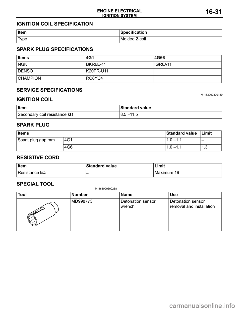
IGNITION SYSTEM
ENGINE ELECTRICAL16-31
IGNITION COIL SPECIFICATION
ItemSpecification
Ty p eMolded 2-coil
SPARK PLUG SPECIFICATIONS
Items4G14G66
NGKBKR6E-11IGR6A11
DENSOK20PR-U11−
CHAMPIONRC8YC4−
SERVICE SPECIFICATIONSM1163000300180
IGNITION COIL
ItemStandard value
Secondary coil resistance kΩ8.5 − 11.5
SPARK PLUG
ItemsStandard valueLimit
Spark plug gap mm4G11.0 − 1.1−
4G61.0 − 1.11.3
RESISTIVE CORD
ItemStandard valueLimit
Resistance kΩ−Maximum 19
SPECIAL TOOL
M1163000600288
ToolNumberNameUse
MD998773Detonation sensor
wrenchDetonation sensor
removal and installation