service MITSUBISHI LANCER 2006 Owner's Guide
[x] Cancel search | Manufacturer: MITSUBISHI, Model Year: 2006, Model line: LANCER, Model: MITSUBISHI LANCER 2006Pages: 800, PDF Size: 45.03 MB
Page 94 of 800
IGNITION SYSTEM
ENGINE ELECTRICAL16-32
ON-VEHICLE SERVICE
IGNITION COIL (WITH BUILT-IN POWER
TRANSISTOR) CHECK
M1163001200324
Check by the following procedure, and replace if
there is a malfunction.
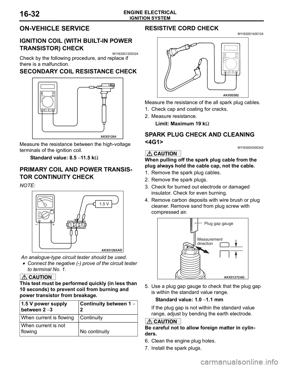
SECONDARY COIL RESISTANCE CHECK
AKX01264
Measure the resist ance bet we en the high- volt ag e
terminals of th
e ign i tio n coil.
St andard va lue: 8.5 − 11 .5 kΩ
PRIM AR Y COIL AND POWER TRANSIS-
TO R CONTINUITY CHECK
NO TE: .•
AKX01265 AD
1.5 V
1 23
+
–
An analogue-t y pe circuit t e ster shou ld be use d .
•Connect the n egative (-) pro v e of the circuit t e ster
to t
e rminal No. 1.
CAUTION
This test must be performed quickly (in less than
10 seconds) to prevent coil from burning and
power transistor from breakage.
1.5 V power supply
between 2
− 3
Continuity between 1 −
2
When current is flowingContinuity
When current is not
flowing
No continuity
RESISTIVE CORD CHECK
M1163001400124
AKX00382
Measure the resistance of the all spark plug cables.
1. Check cap and coating for cracks.
2. Measure resistance.
Limit: Maximum 19 kΩ
SPARK PLUG CHECK AND CLEANING
<4G1>
M1163004300342
CAUTION
When pulling off the spark plug cable from the
plug always hold the cable cap, not the cable.
1. Remove the spark plug cables.
2. Remove the spark plugs.
3. Check for burned out electrode or damaged insulator. Check for even burning.
4. Remove carbon deposits with wire brush or plug cleaner. Remove sand from plug screw with
compressed air.
AKX01272 AG
Plug gap gauge
Measurement
direction
5. Use a plug gap gauge to check that the plug gap is within the standard value range.
Standard value: 1.0 − 1.1 mm
If the plug gap is not within the standard value
range, adjust by bending the earth electrode.
CAUTION
Be careful not to allow foreign matter in cylin-
ders.
6. Clean the engine plug holes.
7. Install the spark plugs.
Page 105 of 800
IGNITION SYSTEM
ENGINE ELECTRICAL16-43
DETONATION SENSOR
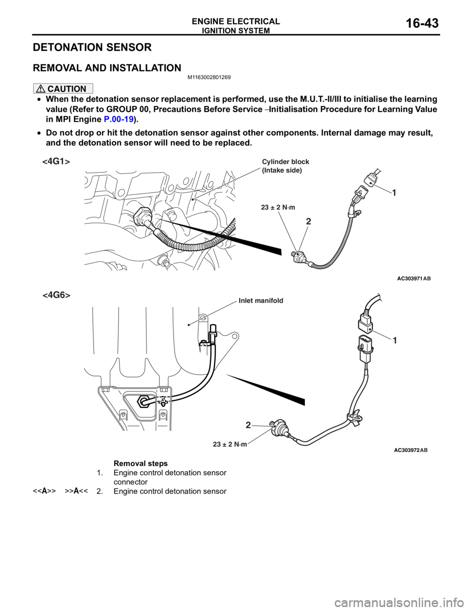
REMOVAL AND INSTALLATION
M1163002801269
CAUTION
•When the detonation sensor replacement is performed, use the M.U.T.-II/III to initialise the learning
value (Refer to GROUP 00, Precautions Before Service
− Initialisation Procedure for Learning Value
in MPI Engine
P.00-19).
•
AC303971
2 1
23 ± 2 N·m
AB
<4G1>Cylinder block
(Intake side)
AC303972
2 1
23 ± 2 N·mAB
<4G6>Inlet manifold
Removal steps
1.Engine control detonation sensor
connector
<>>>A<<2.Engine control detonation sensor
Do not drop or hit the detonation sensor against other components. Internal damage may result,
and the detonation sensor will need to be replaced.
Page 106 of 800
IGNITION SYSTEM
ENGINE ELECTRICAL16-44
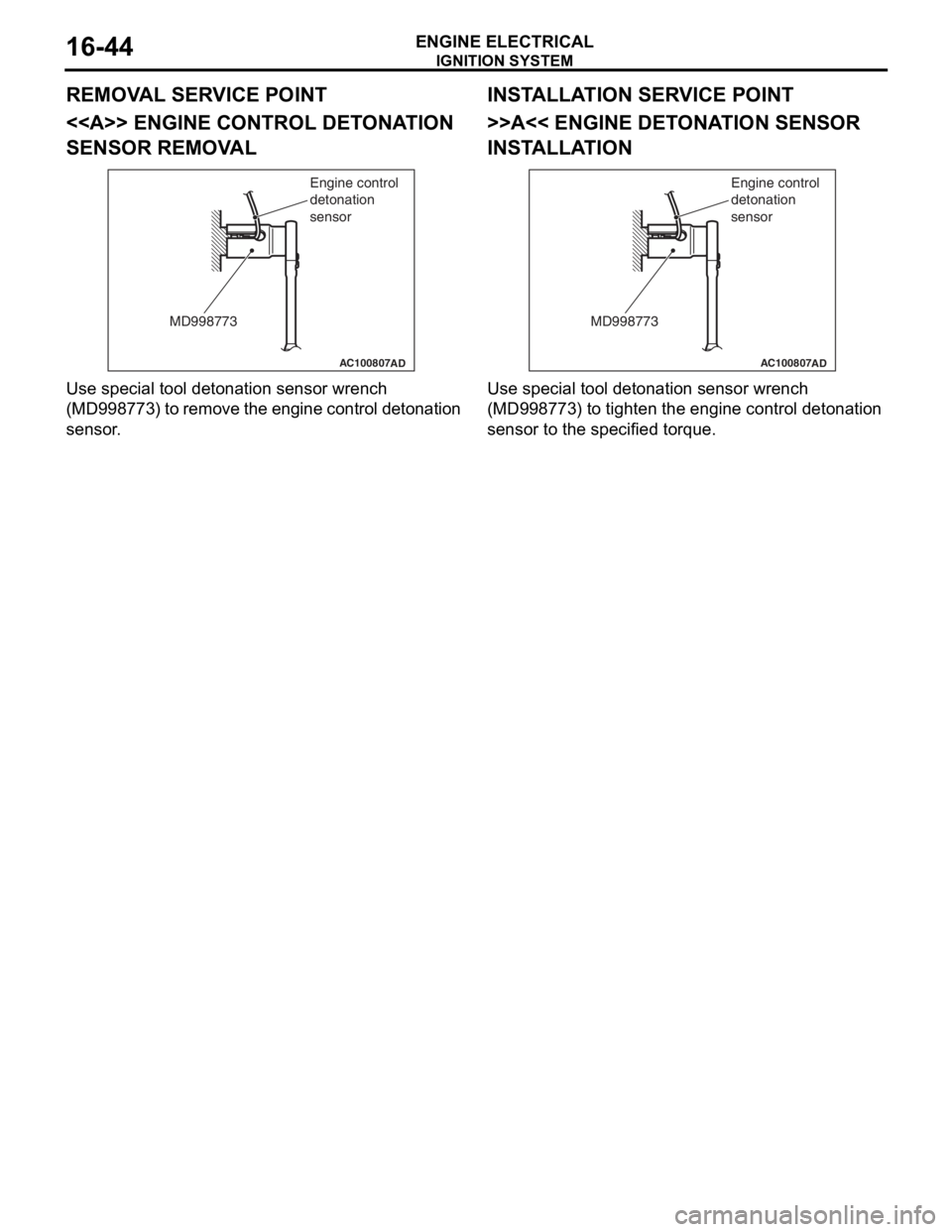
REMOVAL SERVICE POINT
<> ENGINE CONTROL DETONATION
SENSOR REMOVAL
AC100807
MD998773Engine control
detonation
sensor
AD
Use sp
ecial to ol de tonation senso r wrench
(MD9987
73) to remove the engine con t rol det onation
sensor
.
INSTALLA T ION SER VICE POINT
>>A<< ENGINE DETO NA TION SENSOR
INST
ALLA TION
AC100807
MD998773 Engine control
detonation
sensor
AD
Use special to
ol de tonation senso r wrench
(MD9987
73) t o tighten the engine contr o l detona tion
sensor to
the specified torque.
Page 107 of 800
17-1
GROUP 17
ENGINE AND
EMISSION
CONTROL
CONTENTS
ENGINE CONTROL . . . . . . . . . .17-2
GENERAL INFORMATION . . . . . .17-2
SERVICE SPECIFICATIONS. . . . .17-2
ON-VEHICLE SERVICE. . . . . . . . .17-2
ACCEL CABLE CHECK AND
ADJUSTMENT . . . . . . . . . . . . . . . . . . . . 17-2
ACCELERATOR CABLE AND
PEDAL . . . . . . . . . . . . . . . . . . . . . .17-3
REMOVAL AND INSTALLATION . . . . . 17-3
EMISSION CONTROL MPI . . . .17-4
GENERAL INFORMATION . . . . . .17-4
EMISSION CONTROL DEVICE
REFERENCE TABLE . . . . . . . . . .17-4
SERVICE SPECIFICATION(S) . . .17-5
VACUUM HOSE. . . . . . . . . . . . . . .17-5
VACUUM HOSE PIPING DIAGRAM . . . 17-5
VACUUM CIRCUIT DIAGRAM . . . . . . . 17-7
VACUUM HOSE CHECK. . . . . . . . . . . . 17-7
VACUUM HOSE INSTALLATION . . . . . 17-8
CRANKCASE EMISSION CONTROL
SYSTEM . . . . . . . . . . . . . . . . . . . . .17-8
GENERAL INFORMATION (CRANKCASE
EMISSION CONTROL SYSTEM) . . . . . 17-8
COMPONENT LOCATI ON (CRANKCASE
EMISSION CONTROL SYSTEM) . . . . . 17-9
POSITIVE CRANKCASE VENTILATION SYSTEM
CHECK . . . . . . . . . . . . . . . . . . . . . . . . . 17-9
POSITIVE CRANKCASE VENTILATION (PCV)
VALVE CHECK . . . . . . . . . . . . . . . . . . . 17-9
EVAPORATIVE EMISSION CONTROL
SYSTEM . . . . . . . . . . . . . . . . . . . . .17-9
GENERAL INFORMATION (EVAPORATIVE
EMISSION CONTROL SYSTEM) . . . . . 17-9
COMPONENT LOCATION (EVAPORATIVE
EMISSION CONTROL SYSTEM) . . . . . 17-10
PURGE CONTROL SYSTEM CHECK . . 17-10
PURGE PORT VACUUM CHECK . . . . . 17-11
PURGE CONTROL SOLENOID VALVE
CHECK . . . . . . . . . . . . . . . . . . . . . . . . . . 17-11
FUEL VAPOUR CANISTER REMOVAL
AND INSTALLATION . . . . . . . . . . . . . . . 17-12
EXHAUST GAS RECIRCULATION
(EGR) SYSTEM . . . . . . . . . . . . . . .17-12
GENERAL INFORMATION
(EGR SYSTEM) . . . . . . . . . . . . . . . . . . . 17-12
COMPONENT LOCATION
(EGR SYSTEM) . . . . . . . . . . . . . . . . . . . 17-14
EGR SYSTEM CHECK . . . . . . . . . . . . . 17-15
EGR VALVE CHECK . . . . . . . . . . . . . . . 17-15
EGR PORT VACUUM CHECK <4G1>. . 17-16
EGR PORT VACUUM CHECK <4G6>. . 17-16
EGR CONTROL SOLENOID VALVE
CHECK <4G1> . . . . . . . . . . . . . . . . . . . . 17-16
EGR CONTROL SOLENOID VALVE
CHECK <4G6> . . . . . . . . . . . . . . . . . . . . 17-17
EXHAUST GAS RECIRCULATION (EGR)
VALVE REMOVAL AND I
NSTALLATION . . . . . . . . . . . . . . . . . . . . 17-18
CATALYTIC CONVERTER . . . . . .17-19
REMOVAL AND INSTALLATION
<4G1, 4G6-M/T> . . . . . . . . . . . . . . . . . . 17-19
REMOVAL AND INSTALLATION
<4G6-A/T> . . . . . . . . . . . . . . . . . . . . . . . 17-19
Page 108 of 800
ENGINE CONTROL
ENGINE AND EMISSION CONTROL17-2
ENGINE CONTROL
GENERAL INFORMATIONM1171000100277
A cable-type accelerator mechanical sus-
pended-type pedal has been adopted.
SERVICE SPECIFICATIONS
M1171000300088
ItemStandard value
Accel cable play mm1.0 − 2.0
Engine idle speed r/min4G1750 ± 50
4G6750 ± 100
ON-VEHICLE SERVICE
ACCEL CABLE CHECK AND
ADJUSTMENT
M1171000900314
1. Turn A/C and lights OFF. Inspect and adjust at no load.
2. Warm engine until stabilized at idle.
3. Confirm idle speed is at standard value.
Standard value:
750 ± 50 r/min <4G1>
750 ± 100 r/min <4G6>
4. Stop engine. [ignition switch: LOCK (OFF)
position].
5. Confirm there are no sharp bends in the accelerator cable.
6. Check the inner cable for correct slack.
Standard value: 1.0 − 2.0 mm
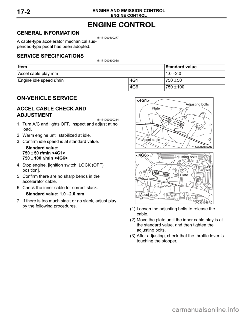
7. If there is too much slack or no slack, adjust play by the following procedures.
AC207966
Adjusting bolts
Plate
Accel cable
AC
<4G1>
AC301055
Adjusting bolts
Plate
Accel cable
AC
<4G6>
(1) Loosen th e adjusting bo lt s to re lease the
cab l e.
(2) M o v e th e pla t e until the inne r cab l e play is a t
the st andard value, an d then tighte n the
adjusting bo lt s.
(3) A f t e r adju s ting, check that the thro ttle leve r is
touching the stoppe r .
Page 110 of 800

EMISSION CONTROL
ENGINE AND EMISSION CONTROL17-4
INSTALLATION SERVICE POINT
>>A<< ACCEL PEDAL PAD INSTALLA-
TION
CAUTION
To prevent damages to the accelerator pedal pad,
warm the thumb area of the accelerator pedal
pad with a dryer, etc. prior to assembling it.
NOTE: If it is difficult to assemble, apply soapy water
to the thumb area to enhance the assembling proc
-
ess.
EMISSION CONTROL
GENERAL INFORMATION
M1173000100370
The emission control system consists of the following
subsystems:
•Crankcase emission control system
•Evaporative emission control system
•
ItemsNameSpecification
Crankcase emission control
systemPositive crankcase ventilation
(PCV) valveVariable flow type
(Purpose: HC reduction)
Evaporative emission control
systemCanister
Purge control solenoid valve
Equipped
Duty cycle type solenoid valve
(Purpose: HC reduction)
Exhaust emission control systemAir-fuel ratio control device - MPI
systemOxygen sensor feedback type
(Purpose: CO, HC, NOx reduction)
Exhaust gas recirculation system
•EGR valve
•EGR control solenoid valve
Equipped
Single type
Duty cycle type solenoid valve
(Purpose: NOx reduction)
Catalytic converterMonolith type
(Purpose: CO, HC, NOx reduction)
Exhaust emission control system
EMISSION CONTROL DEVICE
REFERENCE TABLE
M1173006600135
Related partsCrankcase
emission
control
systemEvaporative
emission
control
systemAir/fuel ratio
control
systemCatalytic
converterExhaust gas
recirculation
system
PCV valve×
Purge control solenoid valve×
MPI system component××
Catalytic converter×
EGR valve×
EGR control solenoid valve×
7.Accelerator control equip bushing
8.Accelerator pedal arm return spring
9.Accelerator pedal arm stopper
10.Accelerator pedal arm bracket
11 .Accelerator pedal arm
>>A<<12.Accelerator pedal pad
13.Accelerator pedal arm stopper
Accelerator pedal assembly
removal steps (Continued)
Page 111 of 800
EMISSION CONTROL
ENGINE AND EMISSION CONTROL17-5
SERVICE SPECIFICATION(S)
M1173000300288
ItemsStandard value
Purge control solenoid valve coil resistance (at 20°C) Ω30 − 34
EGR control solenoid valve coil resistance (at 20°C) Ω29 − 35
VACUUM HOSE
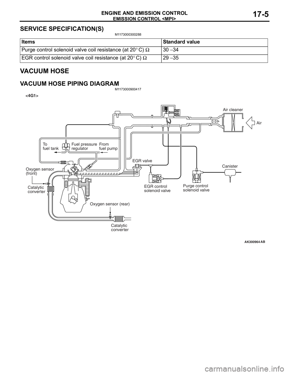
VACUUM HOSE PIPING DIAGRAMM1173000900417
AK300964
To
fuel tankFuel pressure
regulatorFrom
fuel pump
Catalytic
converter Catalytic
converter
Oxygen sensor
(front)
Oxygen sensor (rear)EGR valve
<4G1>
EGR control
solenoid valvePurge control
solenoid valve CanisterAir
AB
Air cleaner
Page 133 of 800
26-1
GROUP 26
FRONT AXLE
CONTENTS
GENERAL INFORMATION . . . . . . . .26-2
SERVICE SPECIFICATIONS . . . . . . .26-3
LUBRICANTS . . . . . . . . . . . . . . . . . .26-3
SPECIAL TOOLS . . . . . . . . . . . . . . . .26-4
ON-VEHICLE SERVICE . . . . . . . . . . .26-7
WHEEL BEARING AXIAL PLAY CHECK . . 26-7
HUB BOLT REPLACEMENT . . . . . . . . . . . 26-7
FRONT AXLE HUB ASSEMBLY . . . .26-8
REMOVAL AND INSTALLATION . . . . . . . . 26-8
INSPECTION. . . . . . . . . . . . . . . . . . . . . . . . 26-11
DISASSEMBLY AND REASSEMBLY . . . . . 26-11
INSPECTION. . . . . . . . . . . . . . . . . . . . . . . . 26-13
DRIVESHAFT ASSEMBLY. . . . . . . . .26-14
REMOVAL AND INSTALLATION . . . . . . . . 26-14
DISASSEMBLY AND REASSEMBLY . . . . . 26-18
INSPECTION. . . . . . . . . . . . . . . . . . . . . . . . 26-21
BJ BOOT (RESIN BOOT)
REPLACEMENT . . . . . . . . . . . . . . . . . . . . . 26-21
Page 135 of 800

SERVICE SPECIFICATIONS
FRONT AXLE26-3
SERVICE SPECIFICATIONS
M1261000300675
ItemStandard valueLimit
Wheel bearing axial play mm−0.05
Hub starting torque N⋅m−1.8
Protruding length of stabilizer bar mounting bolt mm22 ± 1.5−
Setting of TJ boot length mm1300-RH, 1600-A/T-RH85 ± 3−
1300-LH, 1600-M/T,
1600-A/T-LH, 200090 ± 3−
Opening dimension of the
special tool (MB991561) mmWhen the BJ boot band
(small) is crimped2.9−
When the BJ boot band
(large) is crimped2.9 −
Crimped width of the BJ boot band mm2.4 − 2.8−
LUBRICANTS
M1261000400735
ItemSpecified lubricantQuantity
TJ boot greaseRepair kit grease1300-LH, 1600-LH,
2000-LH120 ± 10 g
1300-RH, 1600-A/T-RH11 0 ± 10 g
1600-M/T-RH, 2000-A/T-RH120 ± 10 g
2000-M/T-RH105 ± 10 g
BJ boot greaseRepair kit grease95 ± 10 g
Page 139 of 800
ON-VEHICLE SERVICE
FRONT AXLE26-7
ON-VEHICLE SERVICE
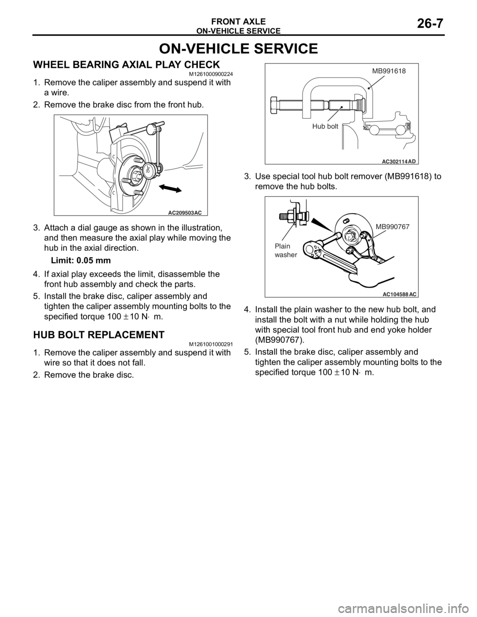
WHEEL BEARING AXIAL PLAY CHECKM1261000900224
1. Remove the caliper assembly and suspend it with a wire.
2. Remove the brake disc from the front hub.
AC209503 AC
3.
Att a ch a dial ga uge a s sh own in the illustration,
an d th en measure the axial play while moving the
hu b in the axial dire ctio n.
Limit: 0.05 mm
4.If axial play e x ceeds t he limit, disassemble the
fro n t hub assemb ly a nd check the p a rt s.
5.In st all the bra k e d i sc, ca lipe r assembly and
tighten th e caliper assemb ly mount ing bolt s to the
specifie d torqu e 100
± 10 N⋅m.
HUB BOL T REPLACEMENTM12610010 0029 1
1.Remove the ca lip er assembly a nd suspe nd it wit h
wire so t hat it does not fa ll.
2.Remove the bra k e d i sc.
AC302114
MB991618
AD
Hub bolt
3.Use spe c ia l too l hub bolt remover (MB99161 8) to
re move the h ub bo lt s.
AC104588
MB990767
Plain
washer
AC
4. In st all the plain wa sher to the n e w hub b o lt, a nd
inst all the bolt with a nu t while hold i ng the hub
wit h spe c ia l too l fron t hub a nd end yoke holder
(MB99076 7).
5.In st all the bra k e d i sc, ca lip er assembly and
tighten th e caliper assembly mount ing bolt s to the
specifie d torqu e 100
± 10 N⋅m.