stop start MITSUBISHI LANCER 2017 8.G Owners Manual
[x] Cancel search | Manufacturer: MITSUBISHI, Model Year: 2017, Model line: LANCER, Model: MITSUBISHI LANCER 2017 8.GPages: 385, PDF Size: 14.34 MB
Page 38 of 385
Seat belts
Seat and restraint systems 4-11
4
Warning display type 2 A tone and warning light are used to remind the driver to fasten the seat belt. If the ignition switch is set to the “ON” posi-tion without the driver’s seat belt being fas- tened, a warning light will come on and a tone will sound for approximately 6 secondsto remind you to fasten your seat belt. If you then drive with the seat belt unfastened for longer than a minute from when the igni-tion switch was turned on, the warning light will come on and blink repeatedly and the tone will sound intermittently.The warning light and the tone will stop after approximately 90 seconds. If you then repeatedly stop and start yourvehicle with the seat belt unfastened, the warning light/display and tone will remind you to fasten your seat belt every time thevehicle starts moving. You will also bereminded to fasten your seat belt in this way when you remove your seat belt while driv- ing. The warning light and the tone go offwhen the seat belt is fastened.
N00418300165
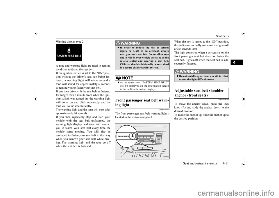
The front passenger seat belt warning light islocated in the instrument panel.
When the key is turned to the “ON” position, this indicator normally comes on and goes off a few seconds later. The light comes on when a person sits on thefront passenger seat but does not fasten the seat belt. It goes off when the seat belt is sub- sequently fastened.
N00406300315
To move the anchor down, press the lock knob (A) and slide the anchor down to the desired position.To move the anchor up, slide the anchor up to the desired position.
WA R N I N G In order to reduce the risk of serious injury or death in an accident, always wear your own seat belt. Do not allow any- one to ride in your vehicle unless he or she is also seated and wearing a seat belt.Children should additionally be restrained in a secure child restraint system.NOTE
At the same time, “FASTEN SEAT BELT” in the multi-information display.
Front passenger seat belt warn- ing light
WA R N I N G Do not install any accessory or sticker that makes the light difficult to see.
Adjustable seat belt shoulder anchor (front seats)
BK0237700US.bo
ok 11 ページ 2016年4月15日 金曜日 午前11時28分
Page 66 of 385
5
Features and controlsBreak-in recommendation
s ..............................................................5-3
Keys ..........................................
.......................................................5-3
Electronic immobilizer (Anti-thef
t starting system) ........................5-4
Keyless entry system (if so equipped) ..............................................5-7Free-hand Advanced Security Transmitter (F.A.S.T.-key) (if so
equipped) ..................................................5-12
Door locks .......................
...............................................................5-34
Power door locks ............
...............................................................5-37
“Child safety locks” for
rear door ..................................................5-38
Trunk lid ...................................
.....................................................5-39
Inside emergency trunk lid
release ................................................5-40
Theft-alarm system (if so
equipped) ...............................................5-41
Power windows ...............
...............................................................5-43
Sunroof (if so equipped
) .........................................
........................5-46
Parking brake ..................
...............................................................5-48
Steering wheel tilt lock lever .........................................................5-49Inside day/night rearview
mirror ...................................................5-50
Outside rearview mirr
ors ...............................................................5-51
Ignition switch ......
.................................................
........................5-52
Steering wheel lock
................................................
........................5-54
Starting and stopping the e
ngine ....................................................5-55
Manual transaxle (if so equipped) ..................................................5-57Continuously variable transmissi
on (CVT) (if so equipped)..........5-59
Electronically controlled 4WD system (if so equipped).................5-68 All-wheel driving opera
tion ...........................................................5-70
Cautions on handling of all-wheel drive vehicles ..........................5-71Service brake ..................
...............................................................5-72
Brake assist system
................................................
........................5-73
Anti-lock braking syst
em .....................................
......................... 5-74
Active Stability Control (ASC
) (if so equipped) ............................ 5-76
Power steering system
..........................................
......................... 5-79
Cruise control (if so eq
uipped) ....................................................... 5-80
Tire pressure monitoring
system ................................................... 5-84
Rear-view camera (if so
equipped)..............
................................... 5-88
Instrument cluster
.................................................
......................... 5-90
Multi-information disp
lay ....................................
......................... 5-91
Indicator light, warning light, and information screen display list .................................................
.......................................... 5-112
Indicators .................................
.................................................... 5-123
Warning lights ................
.................................................
............. 5-124
Information screen disp
lay ...................................
....................... 5-125
Combination headlights and dimmer switch ............................... 5-127 Headlight leveling switch (if
so equipped)................................... 5-132
Turn signal lever ..
.................................................
....................... 5-133
Hazard warning flasher
switch .................................................... 5-133
Front fog light switch (if so
equipped) ......................................... 5-134
Wiper and washer swit
ch ......................................
....................... 5-134
Electric rear window def
ogger switch ......................................... 5-138
Horn switch .............................
.................................................... 5-139
Link System (if so equi
pped) ....................................................... 5-139
Bluetooth
® 2.0 interface (if so
equipped)..................................... 5-139
USB input terminal
...............................................
....................... 5-160
Sun visors ......................
.................................................
............. 5-163
12 V power outlet ..........
.................................................
............. 5-163
Interior lights .................
.................................................
............. 5-164
Storage spaces ................
.................................................
............. 5-166
BK0237700US.bo
ok 1 ページ 2016年4月15日 金曜日 午前11時28分
Page 82 of 385
Free-hand Advanced Security Transmit
ter (F.A.S.T.-key) (if so equipped)
Features and controls 5-17
5
N00513600021
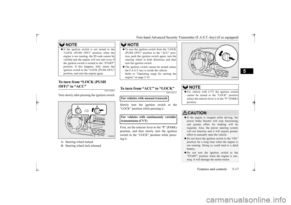
Turn slowly after pressing the ignition switch.
N00513701117
Slowly turn the ignition switch to the “LOCK” position while pressing it. First, set the selector lever to the “P” (PARK) position, and then slowly turn the ignitionswitch to the “LOCK” position while press- ing it.
If the ignition switch is not turned to the “LOCK (PUSH OFF)” position when the engine is not running, the ID code cannot be verified and the engine will not start even if the ignition switch is turned to the “START” ignition switch to the “LOCK (PUSH OFF)” position, and start the engine again.
To turn from “LOCK (PUSH OFF)” to “ACC”
A- Steering wheel locked B- Steering wheel lock released
NOTE
NOTE
To turn the ignition switch from the “LOCK (PUSH OFF)” position to the “ACC” posi- tion, push the ignition switch again, turn the steering wheel in both directions and then turn the ignition switch. The ignition switch cannot be turned unless the F.A.S.T.-key is inside the vehicle.Refer to “Operating range for starting the engine” on page 5-14.
To turn from “ACC” to “LOCK”
For vehicles with manual transaxle For vehicles with continuously variable transmission (CVT)
NOTE
For vehicle with CVT the ignition switch cannot be turned to the “LOCK” position unless the selector lever is in the “P” (PARK) position.CAUTION If the engine is stopped while driving, the power brake booster will stop functioning and greater effort for braking will berequired. Also, the power steering system will not function and it will require greater effort to manually steer the vehicle. Do not leave the ignition switch in the “ON” position for a long time when the engine isnot running. Doing so could lead to a dead battery. Do not turn the ignition switch to the “START” position when the engine is run- ning. It will damage the starter motor.
BK0237700US.bo
ok 17 ページ 2016年4月15日 金曜日 午前11時28分
Page 89 of 385
![MITSUBISHI LANCER 2017 8.G Owners Manual Free-hand Advanced Security Transmitter (F.A.S.T.-key) (if so equipped) 5-24 Features and controls
5
1. [For vehicles with manual transaxle] Push the emergency key in at the “ACC”position and keep MITSUBISHI LANCER 2017 8.G Owners Manual Free-hand Advanced Security Transmitter (F.A.S.T.-key) (if so equipped) 5-24 Features and controls
5
1. [For vehicles with manual transaxle] Push the emergency key in at the “ACC”position and keep](/img/19/7464/w960_7464-88.png)
Free-hand Advanced Security Transmitter (F.A.S.T.-key) (if so equipped) 5-24 Features and controls
5
1. [For vehicles with manual transaxle] Push the emergency key in at the “ACC”position and keep it
depressed until it is
turned to the “LOCK” position, and remove.[For vehicles with continuously variable transmission (CVT)] First, set the selector lever to the “P”(PARK) position, and then slowly turn the ignition switch to the “LOCK” position while pressing it.
2. Install the cover of the ignition switch. 3. Reinsert the emergency key into theF. A . S . T. - k e y.
Steering wheel lock
NOTE
When the ignition switch cannot be turned from the “LOCK” position to the “ACC”position, turn the ignition switch while turn- ing the steering wheel in both directions.
To turn from “ACC” to “LOCK”
NOTE
For vehicles with CVT, the emergency key cannot be removed unless the selector lever is set to the “P” (PARK) position.NOTE
Always install the cover of the ignition switch when not using the emergency key. Not doing so could cause damage if foreign material such as dust gets into the keyhole ofthe ignition switch.
CAUTION Do not turn the ignition switch to the LOCK position while the vehicle is moving. This will cause the steering wheel to lock, making it impossible to operate the vehicle. If the engine is stopped while driving, the power brake booster will stop functioning and greater effort for braking will berequired. Also, the power steering system will not function and it will require greater effort to manually steer the vehicle. Do not leave the ignition switch in the “ON” position for a long time when the engine isnot running. The battery will run down. Do not turn the ignition switch to the “START” position when the engine is run- ning. It will damage the starter motor.
BK0237700US.bo
ok 24 ページ 2016年4月15日 金曜日 午前11時28分
Page 106 of 385
Theft-alarm system (if so equipped)
Features and controls 5-41
5
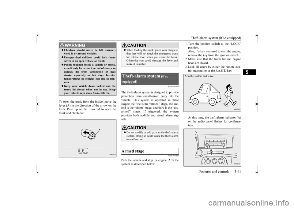
To open the trunk from the inside, move the lever (A) in the direction of the arrow on the lever. Push up on the trunk lid to open the trunk and climb out.
N00510201300
The theft-alarm system is designed to provide protection from unauthorized entry into the vehicle. This system is operated in threestages: the first is the “armed” stage, the sec- ond is the “alarm” stage,
and third is the “dis-
armed” stage. If triggered, the systemprovides both audible and visual alarm sig- nals.
N00510301183
Park the vehicle and stop the engine. Arm the system as described below.
1. Turn the ignition switch to the “LOCK” position. Also, if a key was used to start the engine, remove the key from the ignition switch.2. Make sure that the trunk lid and engine hood are closed. 3. Lock all doors by either the remote con-trol transmitter or the F.A.S.T.-key. At this time, the theft-alarm indicator (A) on the audio panel flashes for confirma-tion.
WA R N I N G Children should never be left unsuper- vised in or around vehicles. Unsupervised children could lock them- selves in an open vehicle or trunk. People trapped inside a vehicle or trunk, even if only for a short period of time, canquickly die from suffocation or heat stroke, especially on hot days. Interior temperatures in vehicles can rise in min-utes. Keep your vehicle doors locked and the trunk lid closed when not in use. Keep your vehicle keys away from children.
CAUTION When loading the trunk, place your things so that they will not touch the emergency trunk lid release lever when you close the trunk. Otherwise you could damage the lever and make it unusable.
Theft-alarm system
(if so
equipped)
CAUTION Do not modify or add parts to the theft-alarm system. Doing so could cause the theft-alarm to malfunction.
Armed stage
Arm the system and leave
BK0237700US.bo
ok 41 ページ 2016年4月15日 金曜日 午前11時28分
Page 119 of 385
![MITSUBISHI LANCER 2017 8.G Owners Manual Steering wheel lock 5-54 Features and controls
5
position, and then turn the key to the “LOCK” position and remove it.
N00512500195
[For vehicles equipped with the F.A.S.T.-key]For information on MITSUBISHI LANCER 2017 8.G Owners Manual Steering wheel lock 5-54 Features and controls
5
position, and then turn the key to the “LOCK” position and remove it.
N00512500195
[For vehicles equipped with the F.A.S.T.-key]For information on](/img/19/7464/w960_7464-118.png)
Steering wheel lock 5-54 Features and controls
5
position, and then turn the key to the “LOCK” position and remove it.
N00512500195
[For vehicles equipped with the F.A.S.T.-key]For information on operations for vehicles equipped with the F.A.S.T.-key, refer to “F.A.S.T.-key: Steering wheel lock” on page5-20. [Except for vehicles equipped with the F. A . S . T. - k e y ]
Remove the key at the “LOCK” position. Turn the steering wheel until it is locked. Turn the key to the “ACC” position while moving the steering wheel slightly.
NOTE
For vehicles with a CVT, the key cannot be removed unless the selector lever is set to the“P” (PARK) position, wh
ich allows the igni-
tion switch to turn to the “LOCK” position.CAUTION Do not remove the ignition key from the ignition switch while driving. The steering wheel will lock, causing loss of control. If the engine is turned off while driving, the power brake booster will stop functioning and braking efficiency will be reduced. Also,the power steering system will not function and it will require greater effort to manually steer the vehicle.CVT
Do not leave the key in the “ON” position for a long time when the engine is not running. This will cause the battery to run down. Do not turn the key to the “START” position when the engine is running. It will damage the starter motor.
Steering wheel lock
CAUTION
To l o c k To u n l o c k
CAUTION Remove the key when leaving the vehicle.NOTE
If the front wheels are turned, the anti-theft lock may sometimes make it difficult to turn the key from “LOCK” position to “ACC” position. Firmly turn the steering wheel tothe left or to the right as you turn the key.
BK0237700US.bo
ok 54 ページ 2016年4月15日 金曜日 午前11時28分
Page 120 of 385
Starting and stopping the engine Features and controls 5-55
5
N00542101096
Do not operate the starter motor continu- ously for longer than
15 seconds as this
could run the battery down or damage thestarter motor. If the engine does not start,turn the ignition switch back to the “LOCK” position, wait a few seconds, and then try again. Trying repeatedly withthe engine or starter motor still turning will damage the starter mechanism. If the engine will not start because the bat- tery is weak or discharged, refer to “Jump-starting the engine” (on page 8-2) for instructions. The engine is warmed up enough for driv- ing when the bar graph of engine coolant temperature display starts to move. A lon-ger warm up period will only consume extra fuel.
N00542201198
[For vehicles equipped with the F.A.S.T.- key.]For information on operation for vehicles equipped with the F.A.S.T.-key, refer to “F.A.S.T.-key: Starting the engine” on page5-20. [Except for vehicles equipped with the F. A . S . T. - k e y. ]Your vehicle is equipped with an electroni- cally controlled fuel injection system, which automatically controls the release of fuel.
There is usually no need to depress the accel- erator pedal when starting the engine. The starter should not be run for more than 15 seconds at a time.To prevent battery drain, wait a few seconds between attempts to restart the engine. 1. Make sure all occupants are properly seated with seat belts fastened 2. Insert the ignition key. 3. Make sure the parking brake is applied.4. Press and hold the brake pedal downfirmly with your right foot. 5. Press and hold the clutch pedal all the way down (manual transaxle). 6. On vehicles with manual transaxle, place the gearshift lever in the “N” (Neutral) position.On vehicles with continuously variable transmission (CVT), make sure the selec- tor lever is in the “P” (PARK) position.
Starting and stopping the engine Tips for starting
WA R N I N G Never run the engine in a closed or poorly ventilated area any longer than is needed to move your vehicle out of the area. Car- bon monoxide gas, which is odorless and extremely poisonous, could build up andcause serious injury or death.CAUTION Do not push-start the vehicle.Do not run the engine
at high rpms or drive
at high speeds until the engine has had a chance to warm up. Release the ignition switch as soon as the engine starts. Otherwise, the starter motorwill be damaged.
Starting the engine
NOTE
For models equipped with a manual trans- axle, the starter will not operate unless the clutch pedal is fully depressed (Clutch inter-lock). This is a safety feature.
BK0237700US.bo
ok 55 ページ 2016年4月15日 金曜日 午前11時28分
Page 121 of 385
Starting and stopping the engine 5-56 Features and controls
5
7. Turn the ignition switch to the “ON” posi- tion and make certain that all warning lights are functioning properly beforestarting the engine.8. Turn the ignition switch to the “START” pedal. Release the key when the enginestarts.
After several attempts, you may experience that the engine still does not start. 1. Make sure that all electric devices, such as lights, air conditioning blower and rearwindow defogger, are turned off.
2. While depressing the brake pedal on vehi- cles equipped with continuously variable transmission (CVT) or the clutch pedal on the vehicles equipped with manual trans-axle, press the accelerator pedal halfway and hold it there, then crank the engine. Release the accelerator pedal, immedi-ately after the engine starts. 3. If the engine still will not start, the engine could be flooded with too much gasoline.While depressing the brake pedal on vehi-cles equipped with CVT or the clutch pedal on the vehicles
equipped with man-
ual transaxle, push the accelerator pedalall the way down and hold it there, then crank the engine for 5 to 6 seconds. Return the ignition switch to the “LOCK”position and release the accelerator pedal. Wait a few seconds, and then crank the engine again for 5 to 6 seconds whiledepressing the brake pedal or the clutch pedal, but do not push the accelerator pedal. Release the ignition key if theengine starts. If the engine fails to start, repeat these procedures. If the engine still will not start, contact your local Mitsubi-shi Motors dealer or a repair facility of your choice for assistance.
When the ambient temperature is -4 °F (-20 °C) or lower on vehicles with CVT, itmay not be possible to start from a standstill even with the selector lever in the “D” (DRIVE) or “R” (REVERSE) position.This phenomenon occurs because the trans-axle has not warmed up sufficiently; it does not indicate a problem. If it occurs, place the selector lever in the “P” (PARK) position andlet the engine idle for at least 10 minutes. The transaxle will warm up, and you will be able to start normally.Do not leave the vehicle during warm-up operation.
N00542301102
1. Bring the vehicle to a complete stop. 2. Fully engage the parking brake while depressing the brake pedal. 3. For vehicles with a manual transaxle, turn the ignition switch to the “LOCK” posi- tion to stop the engine, and then move thegearshift lever to the 1st (on a uphill) or “R” (Reverse) (on a downhill) position.
NOTE
On vehicles with CVT, the starter will not operate unless the selector lever is in the “P” (PARK) or “N” (NEUTRAL) position. For safety reasons, start the engine in the “P” (PARK) position so that the wheels arelocked.NOTE
Minor noises may be heard on engine start- up. These will disappear as the engine warms up.
When the engine is hard to start
Startability of continuously vari- able transmission (CVT) vehicles at extremely cold ambient temper- ature Stopping the engine
BK0237700US.bo
ok 56 ページ 2016年4月15日 金曜日 午前11時28分
Page 122 of 385
Manual transaxle (if so equipped)
Features and controls 5-57
5
For vehicles with continuously variable transmission (CVT), place the selector lever in the “P” (PARK) position, and then turn the ignition switch to the“LOCK” position to stop the engine.
N00512701165
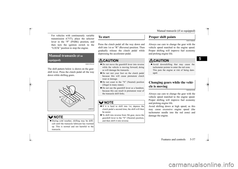
The shift pattern below is shown on the gear-shift lever. Press the clutch pedal all the way down while shifting gears.
Press the clutch pedal all the way down and shift into 1st or “R” (Reverse) position. Thengradually release the clutch pedal while depressing the accelerator pedal.
N00537400049
Always use care to change the gear with the vehicle speed matched to the engine speed.Proper shifting will improve fuel economy and prolong engine life.
N00548101030
Always use care to change the gear with thevehicle speed matched to the engine speed. Proper shifting will improve fuel economyand prolong engine life. Avoid shifting down at high speed, as this may cause excessive engine speed (thetachometer needle into the red zone) and damage the engine.
Manual transaxle
(if so
equipped)
NOTE
During cold weather, shifting may be diffi- cult until the transaxle lubricant has warmed up. This is normal and not harmful to the transaxle.
To start
CAUTION Do not move the gearshift lever into reverse while the vehicle is moving forward; doing so will damage the transaxle. Do not rest your foot on the clutch pedal because this will cause premature clutch wear or damage. Do not coast in the “N” (Neutral) position (illegal in many states). Do not use the gearshift lever as a handrest, because this can result in premature wear ofthe transaxle shift forks.NOTE
If it is hard to shift into 1st, depress the clutch pedal a second time; the shift will then be easier. To shift into reverse from 5th gear, move the gearshift lever to the “N” (Neutral) position, and then shift it into reverse.
Proper shift points
CAUTION Avoid downshifting that may cause the tachometer pointer to enter the red zone. This puts the engine at risk of being dam- aged.
Changing gears while the vehi- cle is moving
BK0237700US.bo
ok 57 ページ 2016年4月15日 金曜日 午前11時28分
Page 127 of 385
Continuously variable transm
ission (CVT) (if so equipped)
5-62 Features and controls
5
N00513900402
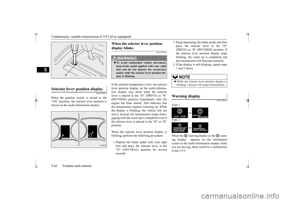
When the ignition switch is turned to the “ON” position, the selector lever position is shown on the multi-information display.
N00585900029
If the ambient temperature is low, the selector lever position display on the multi-informa- tion display may blink when the selector lever is placed in the “D” (DRIVE) or “R”(REVERSE) position immediately after the engine has been started. This indicates that the transmission requires warming up. Whilethe display is blinking, the vehicle will not move, because the transmission keeps disen- gaging until the warm up is completed even ifthe selector lever is placed in the “D” or “R” position. When the selector lever position display is blinking, perform the following procedure: 1. Depress the brake pedal with your right foot and place the selector lever in the “N” (NEUTRAL) position for several seconds.
2. Keep depressing the brake pedal and then place the selector lever in the “D” (DRIVE) or “R” (REVERSE) position. If the selector lever position display stopsblinking, the warm up is completed and the transmission will function normally. 3. If the display is still blinking, repeat steps1 and 2 above.
N00514000194
Ty p e 1
or
Ty p e 2
or
When the warning display or the warn- ing display appears on the information screen in the multi-information display while you are driving, there could be a malfunctionin the CVT.
Selector lever position display
When the selector lever position display blinks
WA R N I N G To avoid unintended vehicle movement, keep brake pedal applied with your right foot and do not depress the acceleratorpedal, while the selector lever position dis- play is blinking.
NOTE
While the selector lever position display is blinking, a buzzer will sound intermittently.
Warning display
BK0237700US.bo
ok 62 ページ 2016年4月15日 金曜日 午前11時28分