relay MITSUBISHI LANCER EVOLUTION 2007 Service Repair Manual
[x] Cancel search | Manufacturer: MITSUBISHI, Model Year: 2007, Model line: LANCER EVOLUTION, Model: MITSUBISHI LANCER EVOLUTION 2007Pages: 1449, PDF Size: 56.82 MB
Page 810 of 1449

22A-2
MANUAL
TRANSMISSION
CONTENTS
GENERAL 3.................................
Outline of Changes 3...........................
GENERAL INFORMATION 3..................
SERVICE SPECIFICATION 3..................
LUBRICANTS 3..............................
SPECIAL TOOLS 4...........................
TROUBLESHOOTING
ON-VEHICLE SERVICE 40....................
Transmission Oil Check 40......................
Transmission Oil Replacement 40................
Transfer Oil Check 40..........................
Transfer Oil Replacement 40....................
Fluid Check
Bleeding
Hydraulic Pressure Check
Wheel Speed Sensor Output Voltage
Measurement
TRANSMISSION CONTROL* 46...............
TRANSFER ASSEMBLY 49...................
TRANSMISSION ASSEMBLY 52...............
4WD-ECU
SENSOR, SWITCH AND RELAY
AYC> 56.....................................
HYDRAULIC UNIT Refer to GROUP27B.......
WARNING REGARDING SERVICING OF SUPPLEMENTAL RESTRAINT SYSTEM (SRS) EQUIPPED VEHICLES
WARNING!
(1) Improper service or maintenance of any component of the SRS, or any SRS-related component, can lead to personal
injury or death to service personnel (from inadvertent firing of the air bag) or to driver and passenger (from rendering
the SRS inoperative).
(2) Service or maintenance of any SRS component or SRS-related component must be performed only at an authorized
MITSUBISHI dealer.
(3) MITSUBISHI dealer personnel must thoroughly review this manual, and especially its GROUP 52B - Supplemental
Restraint System (SRS) before beginning any service or maintenance of any component of the SRS or any SRS-related
component.
NOTE
The SRS includes the following components: SRS-ECU, SRS warning lamp, air bag module, clock spring, and interconnecting
wiring. Other SRS-related components (that may have to be removed/installed in connection with SRS service or maintenance) are
indicated in the table of contents by an asterisk (*).
Page 814 of 1449

MANUAL TRANSMISSION - Troubleshooting
INSPECTION CHART FOR DIAGNOSIS CODES
Diagnosis
code No.Diagnosis itemsReference page
12Power supply voltage (valve power supply) systemopen circuit or short-circuit22A-8
13Fail-safe relay system
21Wheel speed sensor
22Wheel speed sensor
23Wheel speed sensor
24Wheel speed sensor
25Wrong-diameter tire22A-11
26Wheel speed sensor (faulty output signal)22A-13
31Steering wheel sensor
32Steering wheel sensor
33fixed22A-16
34Steering wheel sensor
fixed22A-17
41TPS systemopen circuit or ground22A-18
42short-circuit22A-18
45Pressure sensor systemopen circuit or ground22A-19
46open earth22A-19
47abnormal power supply22A-20
51Longitudinal G sensor systemopen circuit or short-circuit22A-21
52defective sensor22A-22
56Lateral G sensor systemopen circuit or short-circuit22A-23
57defective sensor22A-24
61Stop lamp switch systemopen circuit22A-25
62ACD mode switch systemstuck22A-26
63Parking brake switch systemshort-circuit or not re-
turned to original position22A-27
65ABS monitor systemopen circuit or defective
ABS22A-28
71Proportional valve
GROUP27B
72Directional control valve
GROUP27B.
73Directional control valve
74Proportional valve
Page 815 of 1449

MANUAL TRANSMISSION - Troubleshooting
Diagnosis
code No.Reference page Diagnosis items
81Electric pump relay systemopen circuit or short-circuit22A-29
82electric pump malfunction
or pressure sensor defect22A-30
84AYC control errorRefer to
GROUP 27B.
85ACD control error-
NOTE
Code No.85 is not a code number output due to malfunction, but a code number output when control
for the 4WD-ECU to protect the ACD is stopped in excessive driving. ACD control can be recovered
by turning the ignition switch ON to OFF to ON.
Page 816 of 1449

MANUAL TRANSMISSION - Troubleshooting
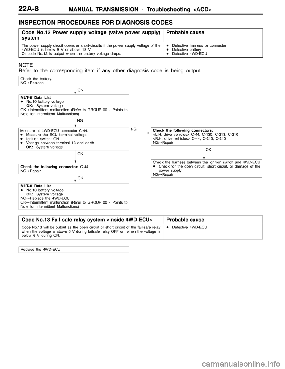
INSPECTION PROCEDURES FOR DIAGNOSIS CODES
Code No.12 Power supply voltage (valve power supply)
systemProbable cause
The power supply circuit opens or short-circuits if the power supply voltage of the
4WD-ECU is below 9 V or above 18 V.
Or code No.12 is output when the battery voltage drops.DDefective harness or connector
DDefective battery
DDefective 4WD-ECU
NOTE
Refer to the corresponding item if any other diagnosis code is being output.
OKOK
NG
NG
OK
Check the battery.
NG→Replace
Measure at 4WD-ECU connector C-44.
DMeasure the ECU terminal voltage.
DIgnition switch: ON
DVoltage between terminal 13 and earth
OK:System voltageCheck the following connectors:
NG→Repair
MUT-IIData List
DNo.10 battery voltage
OK:System voltage
OK→Intermittent malfunction (Refer to GROUP 00 - Points to
Note for Intermittent Malfunctions)
OK
Check the following connector:C-44
NG→Repair
MUT-IIData List
DNo.10 battery voltage
OK:System voltage
NG→Replace the 4WD-ECU
OK→Intermittent malfunction (Refer to GROUP 00 - Points to
Note for Intermittent Malfunctions)
Check the harness between the ignition switch and 4WD-ECU
DCheck for the open circuit, short circuit, or damage of the
power supply
NG→Repair
Code No.13 Fail-safe relay system
Code No.13 will be output as the open circuit or short circuit of the fail-safe relay
when the voltage is above 6 V during failsafe relay OFF or when the voltage is
below 6 V during ON.DDefective 4WD-ECU
Replace the 4WD-ECU.
Page 837 of 1449

MANUAL TRANSMISSION - Troubleshooting
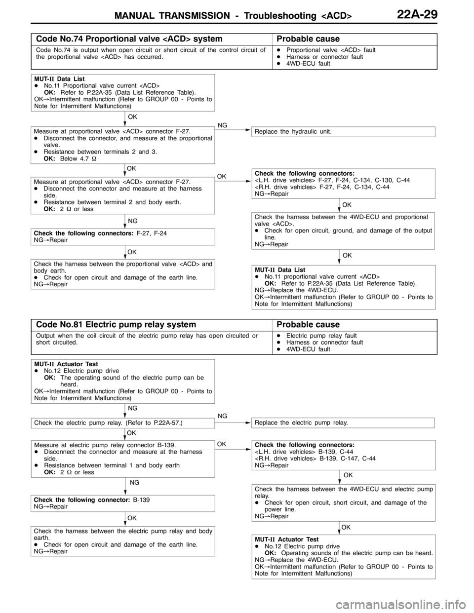
Code No.74 Proportional valve
Code No.74 is output when open circuit or short circuit of the control circuit of
the proportional valve
DHarness or connector fault
D4WD-ECU fault
OK
OK
OK
Replace the hydraulic unit.NG
NG
MUT-IIData List
DNo.11 Proportional valve current
OK:Refer to P.22A-35 (Data List Reference Table).
OK→Intermittent malfunction (Refer to GROUP 00 - Points to
Note for Intermittent Malfunctions)
MUT-IIData List
DNo.11 proportional valve current
OK:Refer to P.22A-35 (Data List Reference Table).
NG→Replace the 4WD-ECU.
OK→Intermittent malfunction (Refer to GROUP 00 - Points to
Note for Intermittent Malfunctions)
OK
Measure at proportional valve
DDisconnect the connector, and measure at the proportional
valve.
DResistance between terminals 2 and 3.
OK:Below 4.7Ω
Measure at proportional valve
DDisconnect the connector and measure at the harness
side.
DResistance between terminal 2 and body earth.
OK:2Ωor less
Check the harness between the proportional valve
body earth.
DCheck for open circuit and damage of the earth line.
NG→Repair
Check the following connectors:F-27, F-24
NG→Repair
OK
Check the following connectors:
NG→Repair
OK
Check the harness between the 4WD-ECU and proportional
valve
DCheck for open circuit, ground, and damage of the output
line.
NG→Repair
Code No.81 Electric pump relay systemProbable cause
Output when the coil circuit of the electric pump relay has open circuited or
short circuited.DElectric pump relay fault
DHarness or connector fault
D4WD-ECU fault
OK
OK
NG
Replace the electric pump relay.NG
NG
MUT-IIActuator Test
DNo.12 Electric pump drive
OK:The operating sound of the electric pump can be
heard.
OK→Intermittent malfunction (Refer to GROUP 00 - Points to
Note for Intermittent Malfunctions)
OK
Check the harness between the electric pump relay and body
earth.
DCheck for open circuit and damage of the earth line.
NG→Repair
Check the following connector:B-139
NG→Repair
OK
Check the following connectors:
NG→Repair
Check the electric pump relay. (Refer to P.22A-57.)
Measure at electric pump relay connector B-139.
DDisconnect the connector and measure at the harness
side.
DResistance between terminal 1 and body earth
OK:2Ωor less
MUT-IIActuator Test
DNo.12 Electric pump drive
OK:Operating sounds of the electric pump can be heard.
NG→Replace the 4WD-ECU.
OK→Intermittent malfunction (Refer to GROUP 00 - Points to
Note for Intermittent Malfunctions)
OK
Check the harness between the 4WD-ECU and electric pump
relay.
DCheck for open circuit, short circuit, and damage of the
power line.
NG→Repair
Page 838 of 1449

MANUAL TRANSMISSION - Troubleshooting
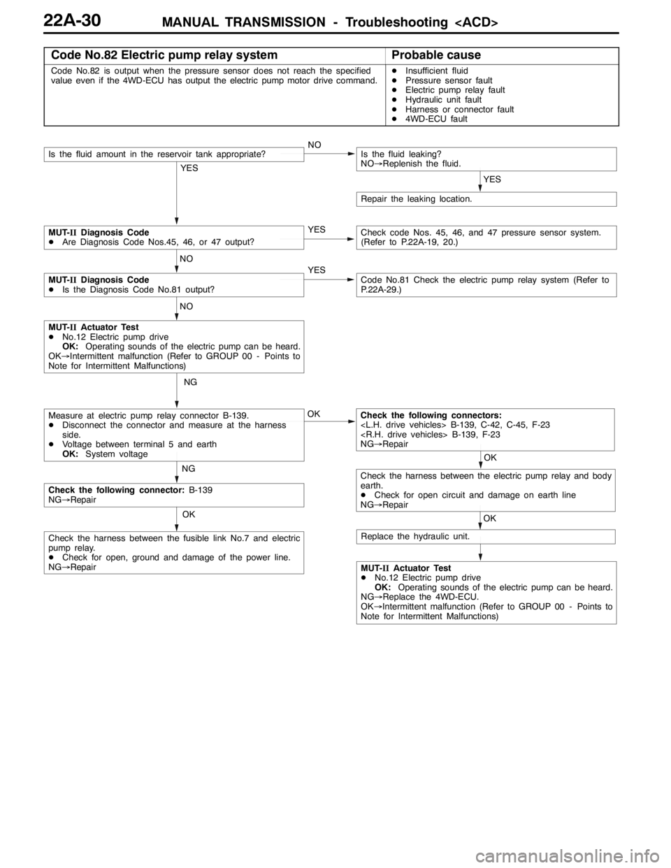
Code No.82 Electric pump relay systemProbable cause
Code No.82 is output when the pressure sensor does not reach the specified
value even if the 4WD-ECU has output the electric pump motor drive command.DInsufficient fluid
DPressure sensor fault
DElectric pump relay fault
DHydraulic unit fault
DHarness or connector fault
D4WD-ECU fault
OK
OK
NG
NG
MUT-IIActuator Test
DNo.12 Electric pump drive
OK:Operating sounds of the electric pump can be heard.
OK→Intermittent malfunction (Refer to GROUP 00 - Points to
Note for Intermittent Malfunctions)
Check the following connectors:
NG→Repair
OK
Check the following connector:B-139
NG→Repair
Check the harness between the fusible link No.7 and electric
pump relay.
DCheck for open, ground and damage of the power line.
NG→Repair
Measure at electric pump relay connector B-139.
DDisconnect the connector and measure at the harness
side.
DVoltage between terminal 5 and earth
OK:System voltage
MUT-IIActuator Test
DNo.12 Electric pump drive
OK:Operating sounds of the electric pump can be heard.
NG→Replace the 4WD-ECU.
OK→Intermittent malfunction (Refer to GROUP 00 - Points to
Note for Intermittent Malfunctions)
YES
NOIs the fluid amount in the reservoir tank appropriate?
YES
Is the fluid leaking?
NO→Replenish the fluid.
Repair the leaking location.
YES
NO
MUT-IIDiagnosis Code
DAre Diagnosis Code Nos.45, 46, or 47 output?Check code Nos. 45, 46, and 47 pressure sensor system.
(Refer to P.22A-19, 20.)
YESCode No.81 Check the electric pump relay system (Refer to
P.22A-29.)
NO
MUT-IIDiagnosis Code
DIs the Diagnosis Code No.81 output?
OK
Check the harness between the electric pump relay and body
earth.
DCheck for open circuit and damage on earth line
NG→Repair
Replace the hydraulic unit.
Page 845 of 1449

MANUAL TRANSMISSION - Troubleshooting
ACTUATOR TEST JUDGEMENT VALUE
Item
no.Check itemTest descriptionNormal state
01Bleeding
according to the steering angle, and operate
the Proportional valve for five minutes.Make sure no air leaks from the bleeder
screw on the transfer.
02Bleeding
according to the steering angle, and operate
the directional valve for five minutes.Make sure no air leaks from the bleeder
screw on the torque transfer differential.
03Check the oil vol-
umeOperate the directional valve to the left and
right for 20 seconds.Check that the oil volume of the reservoir
tank is appropriate.
04Electric pump
driveOperate the electric pump for 5 seconds.Operation sounds of the electric pump
can be heard.
05Check the opera-
tions of the ACDOperate the Proportional valve
supply the maximum oil pressure to the multi
plate clutch.9Generate the tight corner braking
phenomenon.
06Check clutch op-
erations
maximum oil pressure to the left clutch.When the wheels are lifted, speed
difference will occur between the rear
left and right wheels.
07Check clutch op-
erations
maximum oil pressure to the right clutch.When the wheels are lifted, speed
difference will occur between the rear
left and right wheels.
08Control OFFTurn OFF the electric pump relay, and turn
OFF the control of the ACD and AYC.In actual driving, there is difference
between control ON and OFF.
(1) The actuator test can be executed only when all the following conditions are satisfied.
DAll wheel speed sensor inputs below 20 km/h
DNo system malfunction detected
DSteering angle is within±30 degrees from the neutral position
(2) When the actuator test corresponds to one of the following conditions, forced driving will be cleared.
DWhen any one of the wheel speed sensor input is detected to be above 20 km/h (excluding
Item No.08 “Control OFF”.)
DWhen system malfunction is detected (excluding diagnostic code No.82, 84, and 85)
DWhen the forced drive time is exceeded
DWhen the MUT-IIis removed
DWhen the Clear key of the MUT-IIis operated
Page 846 of 1449

MANUAL TRANSMISSION - Troubleshooting
CHECK AT 4WD-ECU TERMINALS
NOTE:
1. *1indicates the eliminated terminal when only ACD is installed.
2. *2indicates the terminal added when only ACD is installed.
Termi-
nal no.
Check itemCheck conditionNormal state
1Proportional valve
Operate the Proportional
valveintheactuatortest
While executing the actuator testSystem voltage
(Item No.01).
3*1Proportional valve
Operate the Proportional
valveintheactuatortest
While executing the actuator testSystem voltage
(Item No. 02).
6Wheel speed sensor
FL
Vehicle is stopping1 V or lessp
7Wheel speed sensor
RR
Vehicle is stopping1 V or lessp
8Wheel speed sensor
RL
Vehicle is stopping1 V or lessp
9Wheel speed sensor
FR
Vehicle is stopping1 V or lessp
10Pressure sensor earthAny time1 V or less
11Lateral G sensorIgnition switch: ON
Vehicle horizontal state2.4 - 2.6 V
134WD-ECU power sup-
l
Ignition switch: OFF0Vpp
plyIgnition switch: ONSystem voltage
14*1Directional valve
valve
actuator test (Item No.
07)After completing the actuator test1 V or less
15*1Directional valve
Operate the directional
valve
While executing the actuator testSystem voltage
tor test (Item No. 06)After completing the actuator test1 V or less
16Electric pump relay
l
When the electric pump motor is not operating0Vppy
power supplyWhile the electric pump motor is operatingSystem voltage
19*2Wheel speed sensor
earth
20*2Wheel speed sensor
earth
21*2Wheel speed sensor
earth
22*2Wheel speed sensor
earth
23Longitudinal G sensorIgnition switch: ON
Vehicle horizontal state2.4 - 2.6 V
Page 864 of 1449

MANUAL TRANSMISSION -Sensor, Switch and Relay
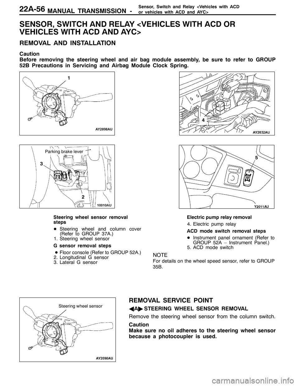
SENSOR, SWITCH AND RELAY
REMOVAL AND INSTALLATION
Caution
Before removing the steering wheel and air bag module assembly, be sure to refer to GROUP
52B Precautions in Servicing and Airbag Module Clock Spring.
1
3
2
4
5
Parking brake lever
Steering wheel sensor removal
steps
DSteering wheel and column cover
(Refer to GROUP 37A.)
1. Steering wheel sensor
G sensor removal steps
DFloor console (Refer to GROUP 52A.)
2. Longitudinal G sensor
3. Lateral G sensorElectric pump relay removal
4. Electric pump relay
ACD mode switch removal steps
DInstrument panel ornament (Refer to
GROUP 52A – Instrument Panel.)
5. ACD mode switch
NOTE
For details on the wheel speed sensor, refer to GROUP
35B.
REMOVAL SERVICE POINT
AA"STEERING WHEEL SENSOR REMOVAL
Remove the steering wheel sensor from the column switch.
Caution
Make sure no oil adheres to the steering wheel sensor
because a photocoupler is used.Steering wheel sensor
Page 865 of 1449

MANUAL TRANSMISSION -Sensor,SwitchandRelay
INSPECTION
ELECTRIC PUMP RELAY CONTINUITY CHECK
1. Using a jumper wire, connect a battery (+) to terminal
13 of the electric pump relay and battery ( - ) to terminal
1.
2. While intermittently disconnecting the jumper wire at the
battery side, check for continuity between terminals 4
and 5 of the electric pump relay.
Jumper wireContinuity between No.4 - No.5
ConnectedContinuity
DisconnectedNo continuity
ACD MODE SWITCH CONTINUITY CHECK
ACD mode switch
terminalACD mode switchContinuity
No.1 - No.2ONContinuity
OFFNo continuity
No.3 - No.4-Continuity