key MITSUBISHI LANCER EVOLUTION 2007 Service Repair Manual
[x] Cancel search | Manufacturer: MITSUBISHI, Model Year: 2007, Model line: LANCER EVOLUTION, Model: MITSUBISHI LANCER EVOLUTION 2007Pages: 1449, PDF Size: 56.82 MB
Page 120 of 1449
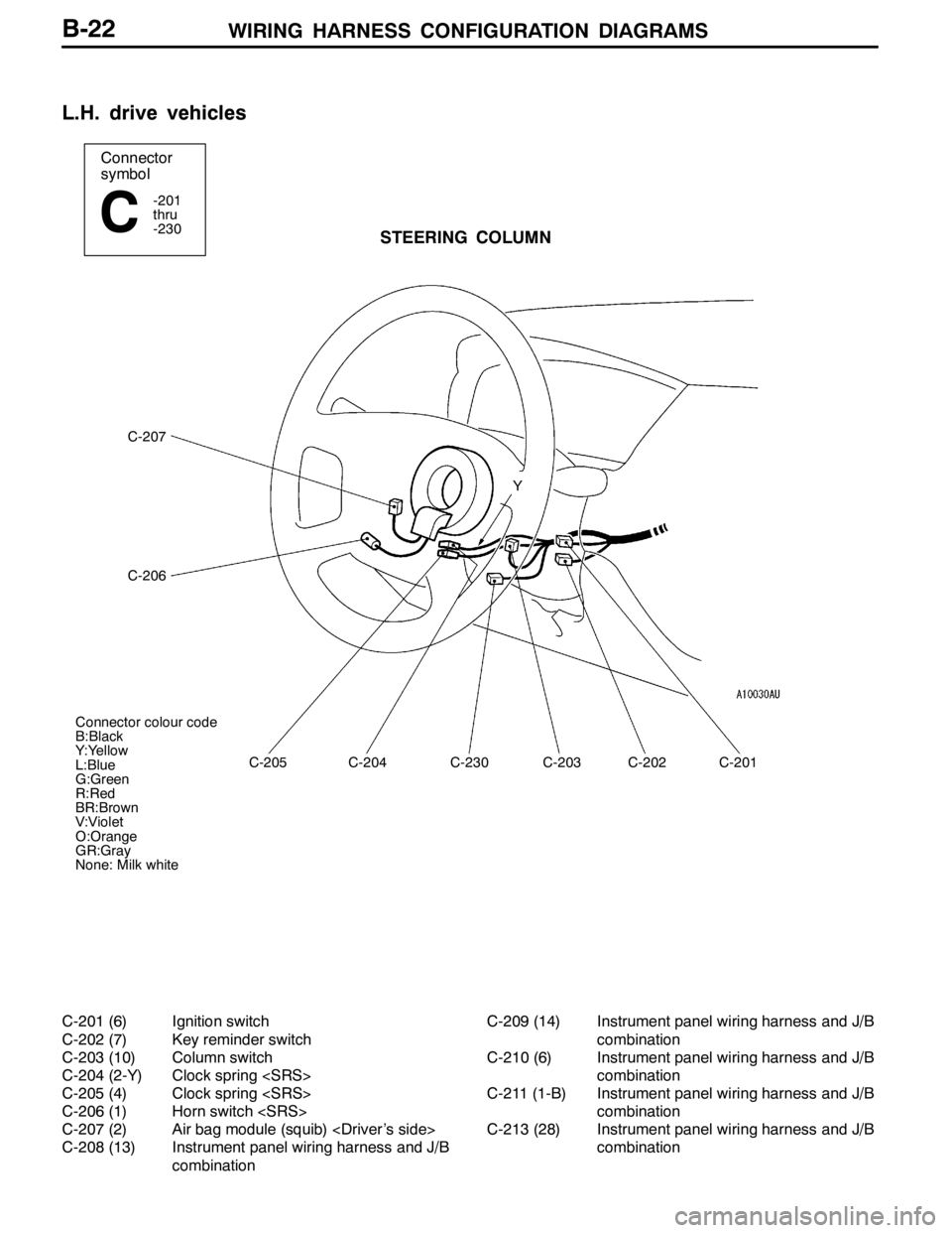
WIRING HARNESS CONFIGURATION DIAGRAMS
Connector
symbol
-201
thru
-230
CSTEERING COLUMN
C-207
C-206
C-205C-204C-230C-203C-202C-201 Y
Connector colour code
B:Black
Y:Yellow
L:Blue
G:Green
R:Red
BR:Brown
V:Violet
O:Orange
GR:Gray
None: Milk white
B-22
L.H. drive vehicles
C-201 (6) Ignition switch
C-202 (7) Key reminder switch
C-203 (10) Column switch
C-204 (2-Y) Clock spring
C-205 (4) Clock spring
C-206 (1) Horn switch
C-207 (2) Air bag module (squib)
C-208 (13) Instrument panel wiring harness and J/B
combinationC-209 (14) Instrument panel wiring harness and J/B
combination
C-210 (6) Instrument panel wiring harness and J/B
combination
C-211 (1-B) Instrument panel wiring harness and J/B
combination
C-213 (28) Instrument panel wiring harness and J/B
combination
Page 126 of 1449
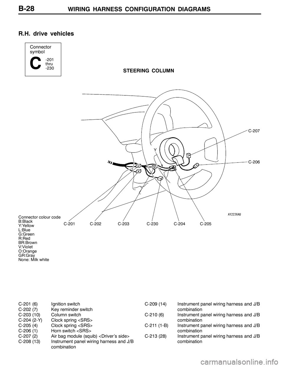
WIRING HARNESS CONFIGURATION DIAGRAMS
Connector colour code
B:Black
Y:Yellow
L:Blue
G:Green
R:Red
BR:Brown
V:Violet
O:Orange
GR:Gray
None: Milk white
Connector
symbol
-201
thru
-230
CSTEERING COLUMN
C-201
C-207
C-206
C-202C-203C-230C-204C-205 Y
B-28
R.H. drive vehicles
C-201 (6) Ignition switch
C-202 (7) Key reminder switch
C-203 (10) Column switch
C-204 (2-Y) Clock spring
C-205 (4) Clock spring
C-206 (1) Horn switch
C-207 (2) Air bag module (squib)
C-208 (13) Instrument panel wiring harness and J/B
combinationC-209 (14) Instrument panel wiring harness and J/B
combination
C-210 (6) Instrument panel wiring harness and J/B
combination
C-211 (1-B) Instrument panel wiring harness and J/B
combination
C-213 (28) Instrument panel wiring harness and J/B
combination
Page 133 of 1449
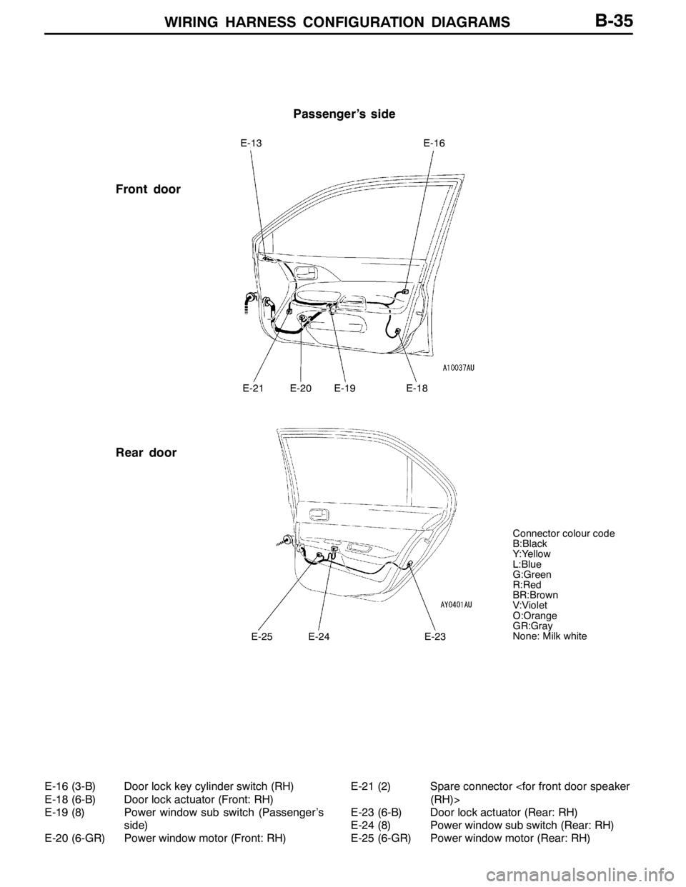
WIRING HARNESS CONFIGURATION DIAGRAMS
Passenger’s side
Front door
Rear door
E-13E-16
E-21E-20E-19E-18
E-25E-24E-23
Connector colour code
B:Black
Y:Yellow
L:Blue
G:Green
R:Red
BR:Brown
V:Violet
O:Orange
GR:Gray
None: Milk white
B-35
E-16 (3-B) Door lock key cylinder switch (RH)
E-18 (6-B) Door lock actuator (Front: RH)
E-19 (8) Power window sub switch (Passenger’s
side)
E-20 (6-GR) Power window motor (Front: RH)E-21 (2) Spare connector
E-23 (6-B) Door lock actuator (Rear: RH)
E-24 (8) Power window sub switch (Rear: RH)
E-25 (6-GR) Power window motor (Rear: RH)
Page 135 of 1449
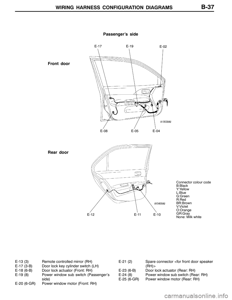
WIRING HARNESS CONFIGURATION DIAGRAMS
Passenger’s side
Front door
Rear door
E-17E-19E-02
E-08E-05E-04
E-12E-11E-10
Connector colour code
B:Black
Y:Yellow
L:Blue
G:Green
R:Red
BR:Brown
V:Violet
O:Orange
GR:Gray
None: Milk white
B-37
E-13 (3) Remote controlled mirror (RH)
E-17 (3-B) Door lock key cylinder switch (LH)
E-18 (6-B) Door lock actuator (Front: RH)
E-19 (8) Power window sub switch (Passenger’s
side)
E-20 (6-GR) Power window motor (Front: RH)E-21 (2) Spare connector
E-23 (6-B) Door lock actuator (Rear: RH)
E-24 (8) Power window sub switch (Rear: RH)
E-25 (6-GR) Power window motor (Rear: RH)
Page 140 of 1449
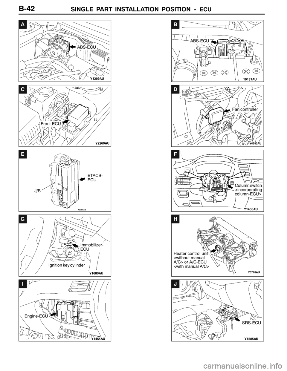
SINGLE PART INSTALLATION POSITION -ECU
A
ABS-ECU
B
ABS-ECU
C
Front-ECU
D
Fan controller
E
ETACS-
ECU
J/B
F
Column switch
G
Ignition key cylinder
Immobilizer-
ECU
H
Heater control unit
I
Engine-ECU
J
SRS-ECU
B-42
Page 362 of 1449

INDEX - In order of connector No.C-6
Wiring diagram
page Circuit diagram page Parts name Connector
No.
CC-130Instrument panel wiring harness and
control wiring harness combinationB-84,87,92,95,100,142,143,148,150,
152,154,157,175,178,198,200,201,
204,205,206,212,213,216,219,228,
229,232,235,237,252,254,255,256,
257B-21,27
C-131Blower switchB-174,180B-21,27
C-132Front wiring harness (LH) and instru-
ment panel wiring harness combinationB-74,78,92,100,105,108,113,117,119,
123,125,128,137,141,150,154,158,
159,164,165,170,172,174,180,185,
188,189,204,205,219,227,237,247,
248,250,252,254B-21,27
C-133Instrument panel wiring harness and
floor wiring harness (LH) combinationB-114,121,126,138,143,144,145,159,
161,165,167,173,249,251B-21,27
C-134Instrument panel wiring harness and
floor wiring harness (LH) combinationB-216,224,234,235,244,245B-21,27
C-135Front wiring harness (LH) and instru-
ment panel wiring harness combinationB-76,82,87,93,95,101,103,104,106,
107,110,111,114,115,118,122,124,127,
128,130,131,132,133,134,135,136,
138,139,140,144,145,146,148,149,
152,153,156,158,164,170,172,175,
177,181,183,185,186,187,190,191,
194,195,196,197,198,206,212,214,
220,222,228,230,238,240,256,257,
258B-21,27
C-136Front wiring harness (LH) and control
wiring harness combination
211,225,243,254B-27
C-137Fog lamp switchB-124,127B-21,27
C-138Remote controlled mirror switchB-192,193B-21,27
C-141Roof antennaB-196B-21,27
C-142ACD mode changeover switchB-214,222,230,240B-21,27
C-146Instrument panel wiring harness and
floor wiring harness (RH) combinationB-93,101,129,148,152,156,203,211,
217,225,233,243B-21,27
C-147Instrument panel wiring harness and
control wiring harness combination
242,244B-27
C-201Ignition switchB-76B-22,28
C-202Key reminder switchB-253,255B-22,28
C-203Column switchB-104,107,112,116,125,128,137,141,
187,191B-22,28
C-204Clock spring
C-205Clock spring
C-206Horn switch
Page 365 of 1449

INDEX - In order of connector No.C-9
Wiring diagram
page Circuit diagram page Parts name Connector
No.
DD-27Fuel gauge unit (Sub)B-148,152,156B-31,33
D-28Seat belt pretensioner (LH)B-249,251B-31,33
D-29Floor wiring harness (RH) and fuel
wiring harness combinationB-93,101B-31,33
D-30Floor wiring harness (RH) and fuel
wiring harness combinationB-93,101,148,152,156,203,211,217,
225,233,243B-31,33
D-32G sensor (Longitudinal)B-200,208,213,221,229,239B-31,33
D-33G sensor (Lateral)B-200,208,213,221,229,239B-31,33
D-34Intercooler water spray switchB-257B-31,33
EE-02Remote controlled mirror (LH)B-192,193B-34,36
E-04Spare connector
E-05Power window motor (Front:LH)B-162,165B-34,36
E-07Power window main switchB-162,163,168,169B-34,36
E-08Door lock actuator (Front:LH)B-170,173B-34,36
E-10Power window motor (Rear:LH)B-161,167B-34,36
E-11Power window sub switch (Rear:LH)B-161,167B-34,36
E-12Door lock actuator (Rear:LH)B-171,173B-34,36
E-13Remote controlled mirror (RH)B-192,193B-34,36
E-16Door lock key cylinder switch (RH)B-170B-35
E-17Door lock key cylinder switch (LH)B-172B-37
E-18Door lock actuator (Front:RH)B-171,172B-35,37
E-19Power window sub switch (Passenger’s
side)B-159,165B-35,37
E-20Power window motor (Front:RH)B-159,168B-35,37
E-21Spare connector
E-23Door lock actuator (Rear:RH)B-171,173B-35,37
E-24Power window sub switch (Rear:RH)B-160,166B-35,37
E-25Power window motor (Rear:RH)B-160,166B-35,37
FF-01Spare connector
F-04Luggage compartment lampB-119,123B-38,39
F-05High mounted stop lampB-144,145B-38,39
F-06Defogger ( - )B-185B-38,39
Page 368 of 1449

INDEX - In order of parts nameC-12
Wiring diagram
page Circuit diagram page Connector
No. Parts name
CColumn switchC-203B-104,107,112,116,125,128,137,141,
187,191B-22,28
Combination meterC-01B-84,87,95,103,106,118,122,126,129,
135,139,148,149,152,153,156,157,
198,206,214,222,230,240,248,250,
256, 258B-18,24
Combination meterC-02B-110,115,118,122,126,129,135,139,
148,149,152,153,156,157,198,206,
248, 250,256,258B-18,24
Condenser fan motorA-45B-177,183B-7,9
Condenser fan motorA-46B-177,183B-7,9
Condenser fan relay (HI)A-07XB-73,177,183B-6,8
Condenser fan relay (LO)A-06XB-73,177,183B-6,8
Control wiring harness and battery
wiring harness combinationB-14B-79,84,91,99,157B-10,14
Control wiring harness and floor wiring
harness (LH) combination
Crank angle sensorB-121B-88,96B-13,16
DDefogger (-)F-06B-185B-38,39
Defogger (+)F-19B-185B-38,39
Defogger relayC-214B-54,55,78,185B-23,29
Detonation sensorB-122B-89,97B-13,17
Diagnosis connectorC-22B-92,100,105,108,113,117,119,123,
125,128,137,141,150,154,158,164,
170,172,188,189,204,205,219,227,
237,247,248,250,252,254B-18,24
Diagnosis connectorC-23B-92,100B-18,24
Direction valve (LH)
Direction valve (RH)
Door lock actuator (Front:LH)E-08B-170,173B-34,36
Door lock actuator (Front:RH)E-18B-171,172B-35,37
Door lock actuator (Rear:LH)E-12B-171,173B-34,36
Door lock actuator (Rear:RH)E-23B-171,173B-35,37
Door lock key cylinder switch (LH)E-17B-172B-37
Door lock key cylinder switch (RH)E-16B-170B-35
Door switch (Front:LH)D-13B-105,112,120,121,158B-30,32
Door switch (Front:RH)D-01B-108,116,120,121,164B-30,32
Page 374 of 1449

INDEX - In order of parts nameC-18
Wiring diagram
page Circuit diagram page Connector
No. Parts name
KKey reminder switchC-202B-253,255B-22,28
LLicence plate lamp (LH)F-13B-110,114B-38,39
Licence plate lamp (RH)F-12B-110,114B-38,39
Luggage compartment lampF-04B-119,123B-38,39
NNo connectionA-08XB-73B-6,8
No connectionA-34-B-9
No connectionB-07XB-73B-10,14
No connectionB-08XB-73B-10,14
No connectionB-10XB-73B-10,14
No connectionC-220B-54,55B-23,29
No connectionB-06XB-73B-10,14
No connectionC-225B-54,55,78B-23,29
No connection
OOil pressure switchB-20B-157B-11,15
Outside/Inside air selection damper
control motor and potentiometerC-10B-175,181B-18,24
Oxygen sensorB-34B-88,96B-11,15
Oxygen sensor (Rear)D-22B-88,96B-31,33
PParking brake switchD-23B-157,201,209,213,221,232,242B-31,33
Power steering oil pressure switchA-48B-90,98B-7,9
Power window main switchE-07B-162,163,168,169B-34,36
Power window motor (Front:LH)E-05B-162,165B-34,36
Power window motor (Front:RH)E-20B-159,168B-35,37
Power window motor (Rear:LH)E-10B-161,167B-34,36
Power window motor (Rear:RH)E-25B-160,166B-35,37
Power window relayC-224B-54,55,158,159,165B-23,29
Power window sub switch (Passenger’s
side)E-19B-159,165B-35,37
Power window sub switch (Rear:LH)E-11B-161,167B-34,36
Power window sub switch (Rear:RH)E-24B-160,166B-35,37
Pressure sensor
Proportioning valve (for ACD control)F-27B-216,224,235,245B-38,39
Proportioning valve (for AYC control)F-28B-235,245B-38,39
Page 415 of 1449

ENGINE -On-vehicle ServiceENGINE -On-vehicle Service11A-9
IGNITION TIMING CHECK
1. Before inspection, set the vehicle to the pre-inspection
condition.
2. Turn the ignition switch to “LOCK” (OFF) position and
then connect the MUT-IIto the diagnosis connector.
3. Set up a timing light.
4. Start the engine and run at idle.
5. Check that engine idle speed is within the standard value.
Standard value: 850±100 r/min
6. Select No.17 of the MUT-IIActuator test.
7. Check that basic ignition timing is within the standard
value.
Standard value: 5_BTDC±3_
8. If the basic ignition timing is outside the standard value,
inspect the MPI system while referring to GROUP 13A
- Troubleshooting.
9. Press the MUT-IIclear key (Select a forced driving cancel
mode) to release the Actuator test.
Caution
If the test is not cancelled, a forced driving will
continue for 27 minutes. Driving under this condition
may damage the engine.
10. Check that ignition timing is at the standard value.
Standard value: approximately 5_BTDC
NOTE
(1) Ignition timing is variable within about±7, even under
normal operating.
(2) And it is automatically further advanced by
approximately 5_from standard value at higher
altitudes.
11. Remove the timing light.
12. Turn the ignition switch to “LOCK” (OFF) position and
then remove the MUT-II.
IDLE SPEED CHECK
1. Before inspection, set the vehicle to the pre-inspection
condition.
2. Turn the ignition switch to “LOCK” (OFF) position, and
then connect the MUT-IIto the diagnosis connector.
3. Set the timing light.
4. Check that the basic ignition timing is within the standard
value.
MUT-II
MUT-II