relay MITSUBISHI LANCER EVOLUTION 2007 Service Repair Manual
[x] Cancel search | Manufacturer: MITSUBISHI, Model Year: 2007, Model line: LANCER EVOLUTION, Model: MITSUBISHI LANCER EVOLUTION 2007Pages: 1449, PDF Size: 56.82 MB
Page 955 of 1449

REAR AXLE -Troubleshooting
ERASING THE DIAGNOSIS CODES
Connect the MUT-IIto the 16-pin diagnosis connector and
erase the diagnosis code. (Refer to GROUP 00 – How to
Use Troubleshooting/Inspection Service Points.)
Caution
Turn the ignition switch to the LOCK (OFF) position before
connecting or disconnecting the MUT-II.
INSPECTION CHART FOR DIAGNOSIS CODE
Diagnosis
code No.Diagnosis itemsReference page
12Power supply voltage (valve power supply) systemopen- or short-circuitRefer to
GROUP22
13Failsafe relay system
GROUP22.
21FR wheel speed sensor systemopen- or short-circuit
22FL wheel speed sensor systemopen- or short-circuit
23RR wheel speed sensor systemopen- or short-circuit
24RL wheel speed sensor systemopen- or short-circuit
25Wrong-diameter tire
26Wheel speed sensor (faulty output signal)
31Steer sensor (ST-1, ST-2, ST-N) systemopen- or short-circuit
32Steer sensor (ST-N) systemshort-circuit
33fixed
34Steer sensor (ST-1, ST-2) systemshort-circuit or output
fixed
41TPS systemopen-circuit or ground
42short-circuit
45Pressure sensor systemopen-circuit or ground
46open earth
47abnormal power supply
51G sensor (longitudinal) systemopen- or short-circuit
52defective sensor
56G sensor (lateral) systemopen- or short-circuit
57defective sensor
Page 956 of 1449

REAR AXLE -Troubleshooting
Diagnosis
code No.Reference page Diagnosis items
61Stop lamp switch systemopen-circuitRefer to
GROUP22
62ACD mode changeover switchstuck
GROUP22.
63Parking brake switch systemshort-circuit or not re-
turned
65ABS monitor systemopen-circuit or defective
ABS
71Proportioning valve
72Directional control valve (right) systemopen- or short-circuit27B-12
73Directional control valve (left) systemopen- or short-circuit27B-13
74Proportioning valve
GROUP22
81Electric pump relay systemopen- or short-circuit
GROUP22.
82electric pump malfunction
or pressure sensor defect
84AYC control error–
85ACD control errorRefer to
GROUP 22.
NOTE
Code No.84 is not a code number output due to malfunction, but a code number output when control
for the 4WD-ECU to protect the AYC is stopped in excessive driving. AYC control can be recovered
by turning the ignition switch ON to OFF to ON.
Page 1077 of 1449

ABS <4WD> -Troubleshooting35B-7
INSPECTION CHART FOR DIAGNOSIS CODES
Diagnosis code No.Inspection itemReference page
11Front right wheel speed sensor (Open circuit or short circuit)35B-9
12Front left wheel speed sensor (Open circuit or short circuit)
13Rear right wheel speed sensor (Open circuit or short circuit)
14Rear left wheel speed sensor (Open circuit or short circuit)
16*ABS-ECU power supply system (Abnormal voltage drop or rise)35B-10
21Front right wheel speed sensor35B-9
22Front left wheel speed sensor
23Rear right wheel speed sensor
24Rear left wheel speed sensor
32Longitudinal G sensor system35B-11
41Front right solenoid valveThe diagnosis codes are output
whenthereisnoresponsetothe
35B-12
42Front left solenoid valve
whenthereis no responsetothe
drive signals for respective solenoid
valvesortheABS ECUpower43Rear right solenoid valvevalves or theABS-ECUpower
supply system is defective.
44Rear left solenoid valve
51Valve relay problem (stays on)35B-30, 31
(Replace the
hydraulic unit and
ABS-ECU.)
52Valve relay problem (stays off) or ABS-ECU power supply system
problem35B-12
53Motor relay problem (stays off) or ABS-ECU power supply system
problem
54Motor relay problem (stays on)35B-30, 31
(Replace the
hydraulic unit and
ABS-ECU.)
55Motor system (seized pump motor) or ABS-ECU power supply system
problem35B-12
63ABS-ECU35B-30, 31
(Replace the
hydraulic unit and
ABS-ECU.)
71Lateral G sensor system35B-13
Page 1082 of 1449

ABS <4WD> -Troubleshooting35B-12
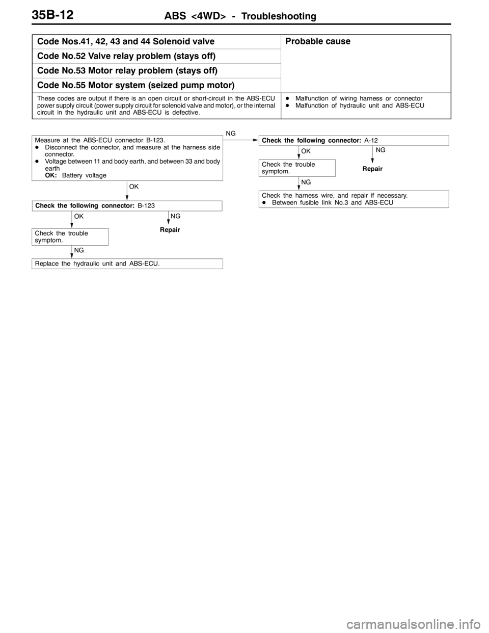
Code Nos.41, 42, 43 and 44 Solenoid valveProbable cause
Code No.52 Valve relay problem (stays off)
Code No.53 Motor relay problem (stays off)
Code No.55 Motor system (seized pump motor)
These codes are output if there is an open circuit or short-circuit in the ABS-ECU
power supply circuit (power supply circuit for solenoid valve and motor), or the internal
circuit in the hydraulic unit and ABS-ECU is defective.DMalfunction of wiring harness or connector
DMalfunction of hydraulic unit and ABS-ECU
NG
Repair
NG
Check the harness wire, and repair if necessary.
DBetween fusible link No.3 and ABS-ECU
NG
Repair
NG
Replace the hydraulic unit and ABS-ECU.
OK
Check the trouble
symptom.
Check the following connector:B-123
OK
OK
Check the trouble
symptom.
Check the following connector:A-12Measure at the ABS-ECU connector B-123.
DDisconnect the connector, and measure at the harness side
connector.
DVoltage between 11 and body earth, and between 33 and body
earth
OK:Battery voltageNG
Page 1105 of 1449

ABS <4WD> -G Sensors and Steering Wheel Sensor35B-35
G SENSORS AND STEERING WHEEL
SENSOR
REMOVAL AND INSTALLATION
Refer to GROUP 22 - Sensor, Switch and Relay.
Parking brake lever
Lateral G sensorLongitudinal G sensor
Steering wheel sensor
Page 1182 of 1449

BODY -DoorsBODY -Doors42-34
"BAOPERATION CHECK
1. Install the glass to the window regulator assembly.
Caution
(1) As fully open position which is programed in the
power window-ECU is released (initialized), the
window regulator assembly should not be
operated until it is installed to the glass.
(2) The clamping prevention function does not
operate the first time that the glass is fully closed.
2. Press the power window switch to fully-open the glass,
and then return the glass toward the fully-close position
about 30 mm each. In the fully-close position, keep on
pressing the power window switch for 0.5 second or more.
NOTE
This operation will program the power window-ECU.
INSPECTION
POWER WINDOW RELAY CONTINUITY CHECK
Battery voltageTerminal No.yg
1345
Not applied
Applied
Power window
relay
123
4
5
Page 1323 of 1449

54A-3
SIDE TURN-SIGNAL LAMP 31............
SPECIAL TOOL 31............................
SIDE TURN-SIGNAL LAMP 31..................
ROOM LAMP 31.........................
TROUBLESHOOTING 31.......................
REAR COMBINATION LAMP 32...........
SPECIAL TOOL 32............................
TROUBLESHOOTING 32.......................
REAR COMBINATION LAMP 32................
HIGH-MOUNTED STOP LAMP 34.........
ON-VEHICLE SERVICE 34......................
High-mounted Stop Lamp Bulb Replacement 34.
HIGH-MOUNTED STOP LAMP 34................
LICENCE PLATE LAMP 35...............
ON-VEHICLE SERVICE 35.....................
License Plate Lamp Replacement 35...........
LICENCE PLATE LAMP 35.....................
HAZARD WARNING LAMP SWITCH 36....
SPECIAL TOOL 36............................
HAZARD WARNING LAMP SWITCH 36.........
HORN 37................................
CIGARETTE LIGHTER 37.................
COLUMN SWITCH 38....................
SPECIAL TOOL 38............................
COLUMN SWITCH 38..........................
CLOCK 40...............................
SPECIAL TOOL 40............................
CLOCK 40....................................
POLE ANTENNA 41......................
ROOF ANTENNA 42......................
DEFOGGER 42...........................
TROUBLESHOOTING 42......................
ON-VEHICLE SERVICE 43.....................
Printed Heater Check 43......................
Defogger Relay Continuity Check 43...........
DEFOGGER SWITCH 43.......................
Page 1330 of 1449

CHASSIS ELECTRICAL -Ignition Switch and Immobilizer System54A-10
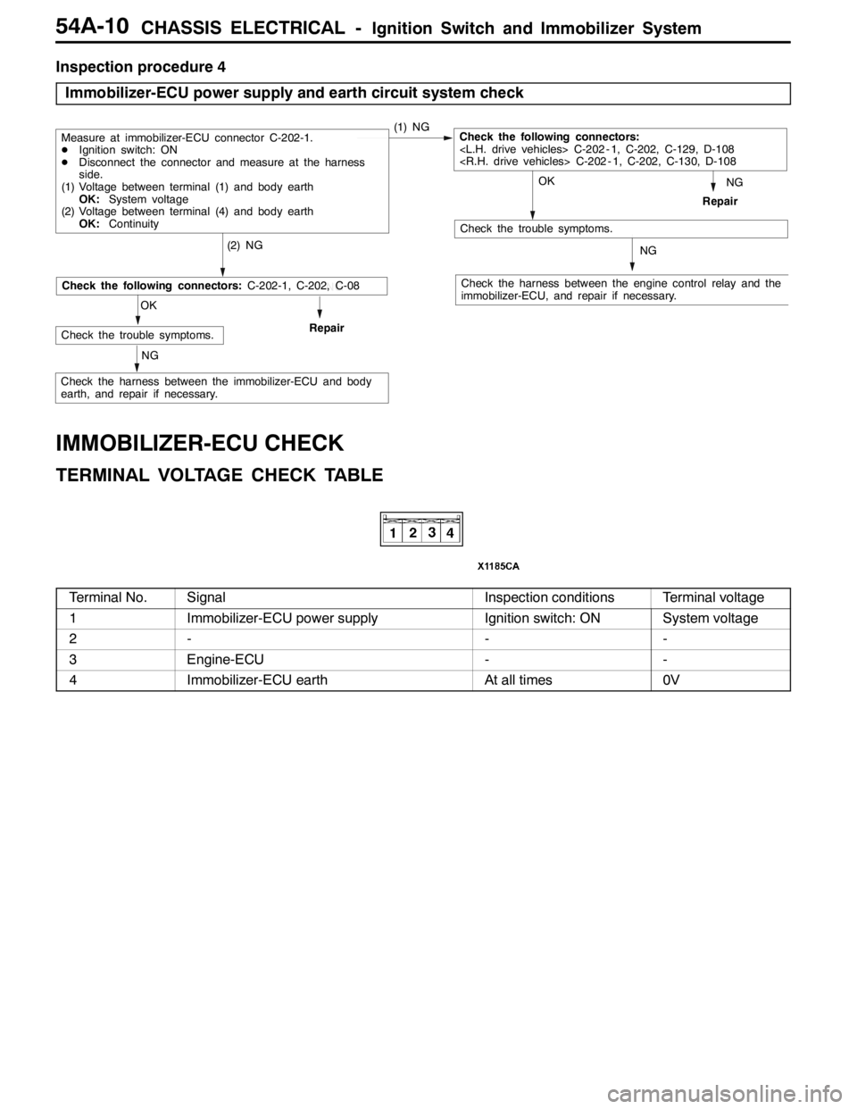
Inspection procedure 4
Immobilizer-ECU power supply and earth circuit system check
NG
Check the harness between the engine control relay and the
immobilizer-ECU, and repair if necessary.
OK
Check the trouble symptoms.
(2) NG
Repair
Measure at immobilizer-ECU connector C-202-1.
DIgnition switch: ON
DDisconnect the connector and measure at the harness
side.
(1) Voltage between terminal (1) and body earth
OK:System voltage
(2) Voltage between terminal (4) and body earth
OK:Continuity(1) NGCheck the following connectors:
NG
NG
OK
Check the trouble symptoms.Repair
NG
Check the following connectors:C-202-1, C-202, C-08
Check the harness between the immobilizer-ECU and body
earth, and repair if necessary.
IMMOBILIZER-ECU CHECK
TERMINAL VOLTAGE CHECK TABLE
Terminal No.SignalInspection conditionsTerminal voltage
1Immobilizer-ECU power supplyIgnition switch: ONSystem voltage
2---
3Engine-ECU--
4Immobilizer-ECU earthAt all times0V
Page 1353 of 1449

CHASSIS ELECTRICAL-Rear Combination Lamp
ILL
ILL
54A-33
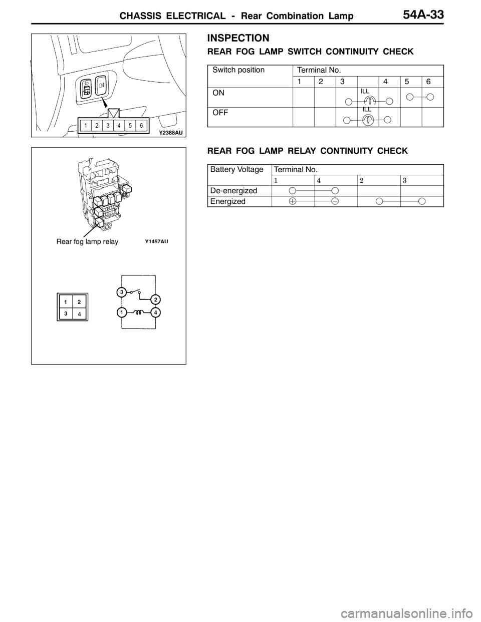
INSPECTION
REAR FOG LAMP SWITCH CONTINUITY CHECK
Switch positionTerminal No.p
123456
ON
OFF
REAR FOG LAMP RELAY CONTINUITY CHECK
Battery VoltageTerminal No.yg
1423
De-energized
Energized
Rear fog lamp relay
Page 1357 of 1449

CHASSIS ELECTRICAL-Hazard Warning Lamp Switch/Horn/Cigarette Lighter
ILL
ILL
54A-37
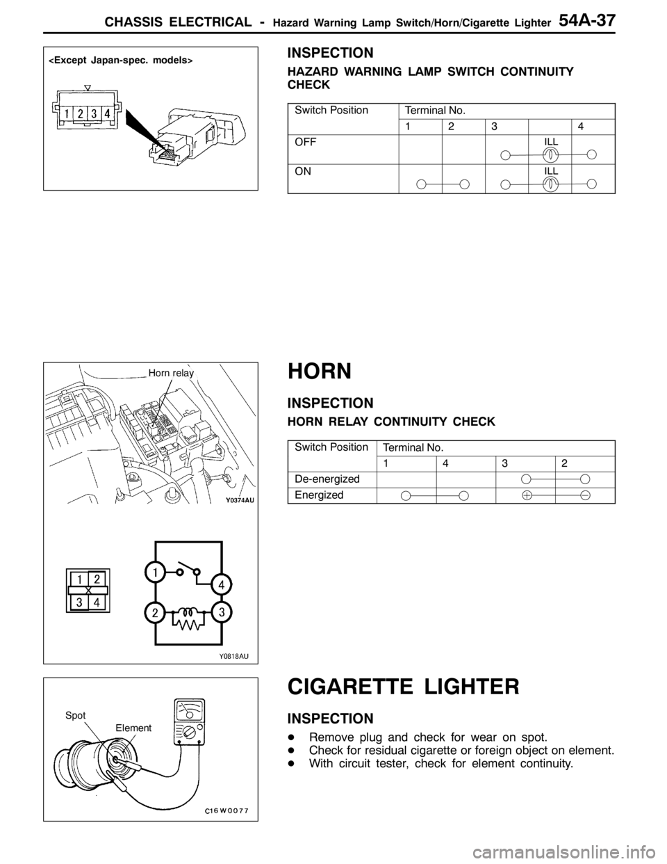
INSPECTION
HAZARD WARNING LAMP SWITCH CONTINUITY
CHECK
Switch PositionTerminal No.
1234
OFF
ON
HORN
INSPECTION
HORN RELAY CONTINUITY CHECK
Switch PositionTerminal No.
1432
De-energized
Energized
CIGARETTE LIGHTER
INSPECTION
DRemove plug and check for wear on spot.
DCheck for residual cigarette or foreign object on element.
DWith circuit tester, check for element continuity.
Horn relay
Spot
Element