relay MITSUBISHI LANCER EVOLUTION 2007 Service Repair Manual
[x] Cancel search | Manufacturer: MITSUBISHI, Model Year: 2007, Model line: LANCER EVOLUTION, Model: MITSUBISHI LANCER EVOLUTION 2007Pages: 1449, PDF Size: 56.82 MB
Page 1363 of 1449
CHASSIS ELECTRICAL -Defogger54A-43
ON-VEHICLE SERVICE
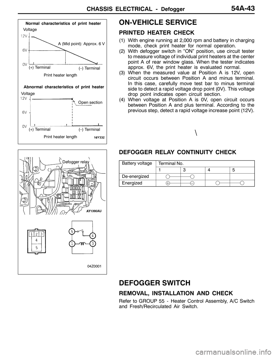
PRINTED HEATER CHECK
(1) With engine running at 2,000 rpm and battery in charging
mode, check print heater for normal operation.
(2) With defogger switch in “ON” position, use circuit tester
to measure voltage of individual print heaters at the center
point A of rear window glass. When the tester indicates
approx. 6V, the print heater is evaluated normal.
(3) When the measured value at Position A is 12V, open
circuit occurs between Position A and minus terminal.
In this case, carefully move test bar to minus terminal
side to detect a rapid voltage drop point (0V). This voltage
drop point indicates open circuit section.
(4) When voltage at Position A is 0V, open circuit occurs
between Position A and plus terminal. According to the
previous step, detect a rapid voltage increase point (12V).
DEFOGGER RELAY CONTINUITY CHECK
Battery voltageTerminal No.yg
1345
De-energized
Energized
DEFOGGER SWITCH
REMOVAL, INSTALLATION AND CHECK
Refer to GROUP 55 - Heater Control Assembly, A/C Switch
and Fresh/Recirculated Air Switch.
(–) Terminal
(–) Terminal
A (Mid point): Approx. 6 V
Normal characteristics of print heater
Abnormal characteristics of print heater
Voltage
Voltage
(+) Terminal
(+) Terminal
Print heater length
Print heater length
Open section
Defogger relay
04Z0001
\
Page 1369 of 1449
SWS -Troubleshooting54B-5
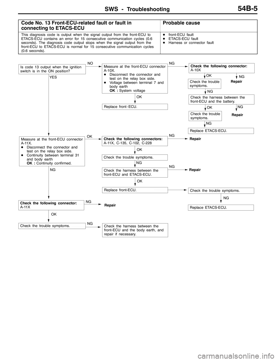
Code No. 13 Front-ECU-related fault or fault in
connecting to ETACS-ECUProbable cause
This diagnosis code is output when the signal output from the front-ECU to
ETACS-ECU contains an error for 15 consecutive communication cycles (0.6
seconds). The diagnosis code output stops when the signal output from the
front-ECU to ETACS-ECU is normal for 15 consecutive communication cycles
(0.6 seconds).Dfront-ECU fault
DETACS-ECU fault
DHarness or connector fault
NG
Repair
NG
Replace ETACS-ECU.
OK
Check the trouble
symptoms.
NG
Repair
NG
Check the harness between the
front-ECU and the battery.
OK
Check the trouble
symptoms.
NG
Replace ETACS-ECU.
OK
Replace front-ECU.Check the trouble symptoms.
NG
Check the harness between the
front-ECU and ETACS-ECU.NG
Repair
OK
Check the trouble symptoms.
OK
Replace front - ECU.
OK
Check the trouble symptoms.NGCheck the harness between the
front-ECU and the body earth, and
repair if necessary.
NG
Check the following connector:
A-11XNG
Repair
YES
Measure at the front-ECU connector
A-11X.
DDisconnect the connector and
test on the relay box side.
DContinuity between terminal 31
and body earth
OK :Continuity confirmed.OKCheck the following connectors:
A-11X, C-135, C-102, C-228NG
Repair
Is code 13 output when the ignition
switch is in the ON position?NOMeasure at the front-ECU connector
A-10X.
DDisconnect the connector and
test on the relay box side.
DVoltage between terminal 7 and
body earth
OK :System voltageNGCheck the following connector:
A-10X
Page 1376 of 1449
SWS -Troubleshooting54B-12
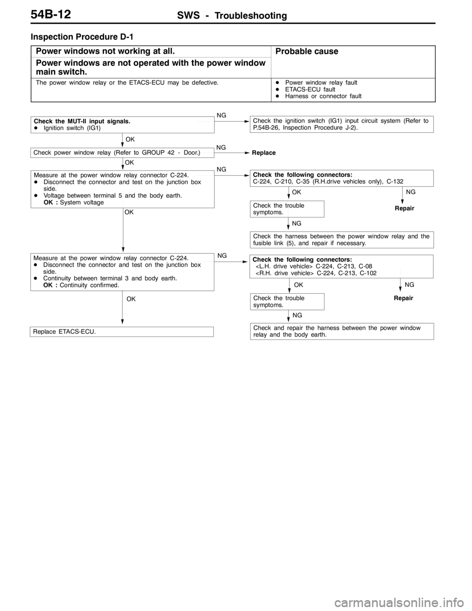
Inspection Procedure D-1
Power windows not working at all.
Probable cause
Power windows are not operated with the power window
main switch.
The power window relay or the ETACS-ECU may be defective.DPower window relay fault
DETACS-ECU fault
DHarness or connector fault
NG
Check the harness between the power window relay and the
fusible link (5), and repair if necessary.
NG
Repair
OK
Check the trouble
symptoms.
OK
NG
Check the following connectors:
C-224, C-210, C-35 (R.H.drive vehicles only), C-132
OK
Check power window relay (Refer to GROUP 42 - Door.)NG
Replace
Check the MUT-II input signals.
DIgnition switch (IG1)NGCheck the ignition switch (IG1) input circuit system (Refer to
P.54B-26, Inspection Procedure J-2).
NG
Check and repair the harness between the power window
relay and the body earth.
NG
RepairOK
Replace ETACS-ECU.
OK
Check the trouble
symptoms.
OK
Measure at the power window relay connector C-224.
DDisconnect the connector and test on the junction box
side.
DContinuity between terminal 3 and body earth.
OK :Continuity confirmed.NGCheck the following connectors:
Measure at the power window relay connector C-224.
DDisconnect the connector and test on the junction box
side.
DVoltage between terminal 5 and the body earth.
OK :System voltage
Page 1378 of 1449
SWS -Troubleshooting54B-14
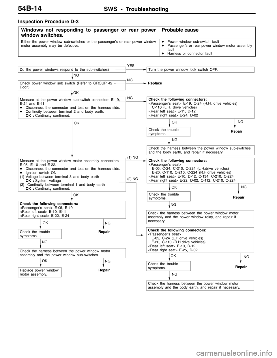
Inspection Procedure D-3
Windows not responding to passenger or rear power
window switches.
Probable cause
Either the power window sub-switches or the passenger’s or rear power window
motor assembly may be defective.DPower window sub-switch fault
DPassenger’s or rear power window motor assembly
fault
DHarness or connector fault
NG
Repair
NG
Check the harness between the power window sub-switches
and the body earth, and repair if necessary.
NG
Repair
NG
Check the harness between the power window motor
assembly and the power window relay, and repair if
necessary.NG
Repair
NG
Check the harness between the power window motor
assembly and the body earth, and repair if necessary.
NG
Repair
OK
Replace power window
motor assembly.
NG
Repair
NG
Check the harness between the power window motor
assembly and the power window sub-switches.
OK
Check the trouble
symptoms.
OK
Check the trouble
symptoms.
(2) NG
Check the following connectors:
E-05, C-24 (L.H.drive vehicles)
E-20, C-110 (R.H.drive vehicles)
OK
Check the trouble
symptoms.
OK
Check the trouble
symptoms.
OK
Check the following connectors:
OK
Measure at the power window motor assembly connectors
E-05, E-10 and E-22.
DDisconnect the connector and test on the harness side.
DIgnition switch ON
(1) Voltage between terminal 3 and body earth
OK :System voltage
(2) Continuity between terminal 1 and body earth
OK :Continuity confirmed.(1) NGCheck the following connectors:
E-05, C-24, C-210, C-224 (L.H.drive vehicles)
E-20, C-110, C-210, C-224 (R.H.drive vehicles)
OK
Measure at the power window sub-switch connectors E-19,
E-24 and E-11
DDisconnect the connector and test on the harness side.
DContinuity between terminal 2 and body earth.
OK :Continuity confirmed.NGCheck the following connectors:
C-110 (L.H. drive vehicles)
Check power window sub switch (Refer to GROUP 42 -
Door.)NG
Replace
YESTurn the power window lock switch OFF.
NO
Do the power windows respond to the sub-switches?
Page 1384 of 1449
SWS -Troubleshooting54B-20
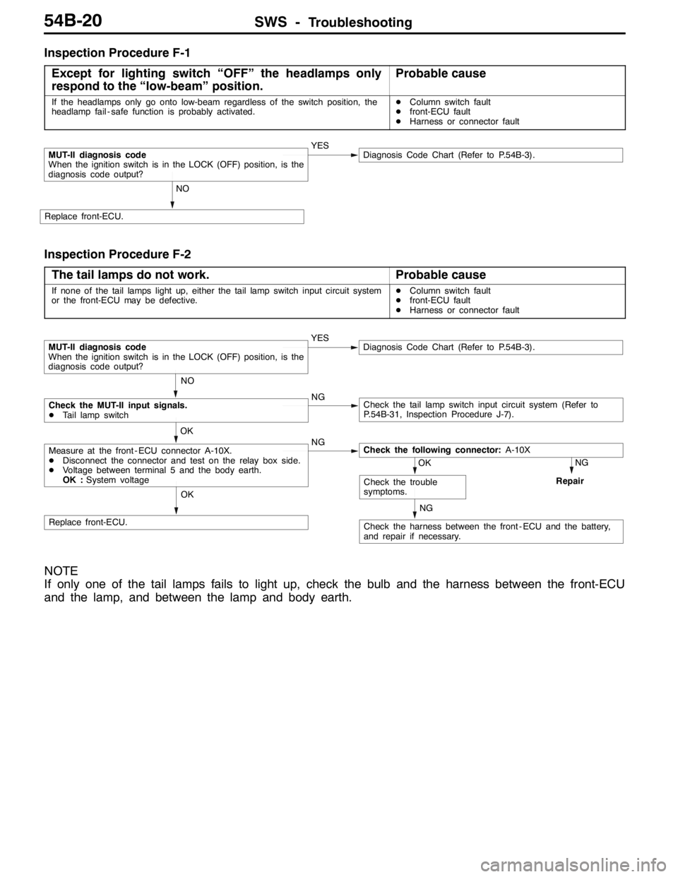
Inspection Procedure F-1
Except for lighting switch “OFF” the headlamps only
respond to the “low-beam” position.
Probable cause
If the headlamps only go onto low-beam regardless of the switch position, the
headlamp fail - safe function is probably activated.DColumn switch fault
Dfront-ECU fault
DHarness or connector fault
NO
Replace front-ECU.
MUT-II diagnosis code
When the ignition switch is in the LOCK (OFF) position, is the
diagnosis code output?YESDiagnosis Code Chart (Refer to P.54B-3).
Inspection Procedure F-2
The tail lamps do not work.
Probable cause
If none of the tail lamps light up, either the tail lamp switch input circuit system
or the front-ECU may be defective.DColumn switch fault
Dfront-ECU fault
DHarness or connector fault
NG
Repair
NG
Check the harness between the front - ECU and the battery,
and repair if necessary.
OK
Replace front-ECU.
OK
Check the trouble
symptoms.
OK
Measure at the front - ECU connector A-10X.
DDisconnect the connector and test on the relay box side.
DVoltage between terminal 5 and the body earth.
OK :System voltageNGCheck the following connector:A-10X
NO
Check the MUT-II input signals.
DTail lamp switchNGCheck the tail lamp switch input circuit system (Refer to
P.54B-31, Inspection Procedure J-7).
MUT-II diagnosis code
When the ignition switch is in the LOCK (OFF) position, is the
diagnosis code output?YESDiagnosis Code Chart (Refer to P.54B-3).
NOTE
If only one of the tail lamps fails to light up, check the bulb and the harness between the front-ECU
and the lamp, and between the lamp and body earth.
Page 1385 of 1449
SWS -Troubleshooting54B-21
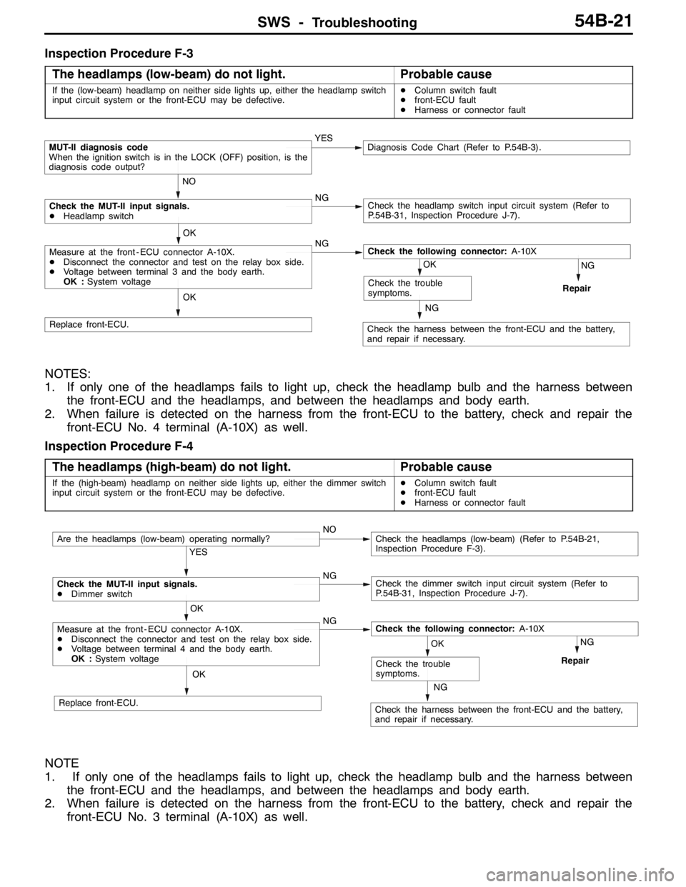
Inspection Procedure F-3
The headlamps (low-beam) do not light.
Probable cause
If the (low-beam) headlamp on neither side lights up, either the headlamp switch
input circuit system or the front-ECU may be defective.DColumn switch fault
Dfront-ECU fault
DHarness or connector fault
NO
Check the MUT-II input signals.
DHeadlamp switchNGCheck the headlamp switch input circuit system (Refer to
P.54B-31, Inspection Procedure J-7).
NG
Repair
NG
Check the harness between the front-ECU and the battery,
and repair if necessary.
OK
Replace front-ECU.
OK
Check the trouble
symptoms.
OK
Measure at the front - ECU connector A-10X.
DDisconnect the connector and test on the relay box side.
DVoltage between terminal 3 and the body earth.
OK :System voltageNGCheck the following connector:A-10X
MUT-II diagnosis code
When the ignition switch is in the LOCK (OFF) position, is the
diagnosis code output?YESDiagnosis Code Chart (Refer to P.54B-3).
NOTES:
1. If only one of the headlamps fails to light up, check the headlamp bulb and the harness between
the front-ECU and the headlamps, and between the headlamps and body earth.
2. When failure is detected on the harness from the front-ECU to the battery, check and repair the
front-ECU No. 4 terminal (A-10X) as well.
Inspection Procedure F-4
The headlamps (high-beam) do not light.
Probable cause
If the (high-beam) headlamp on neither side lights up, either the dimmer switch
input circuit system or the front-ECU may be defective.DColumn switch fault
Dfront-ECU fault
DHarness or connector fault
NG
Check the harness between the front-ECU and the battery,
and repair if necessary.OK
Check the trouble
symptoms.
NG
Repair
OK
Measure at the front - ECU connector A-10X.
DDisconnect the connector and test on the relay box side.
DVoltage between terminal 4 and the body earth.
OK :System voltageNGCheck the following connector:A-10X
YES
Check the MUT-II input signals.
DDimmer switchNGCheck the dimmer switch input circuit system (Refer to
P.54B-31, Inspection Procedure J-7).
OK
Replace front-ECU.
Are the headlamps (low-beam) operating normally?NOCheck the headlamps (low-beam) (Refer to P.54B-21,
Inspection Procedure F-3).
NOTE
1. If only one of the headlamps fails to light up, check the headlamp bulb and the harness between
the front-ECU and the headlamps, and between the headlamps and body earth.
2. When failure is detected on the harness from the front-ECU to the battery, check and repair the
front-ECU No. 3 terminal (A-10X) as well.
Page 1387 of 1449
SWS -Troubleshooting54B-23
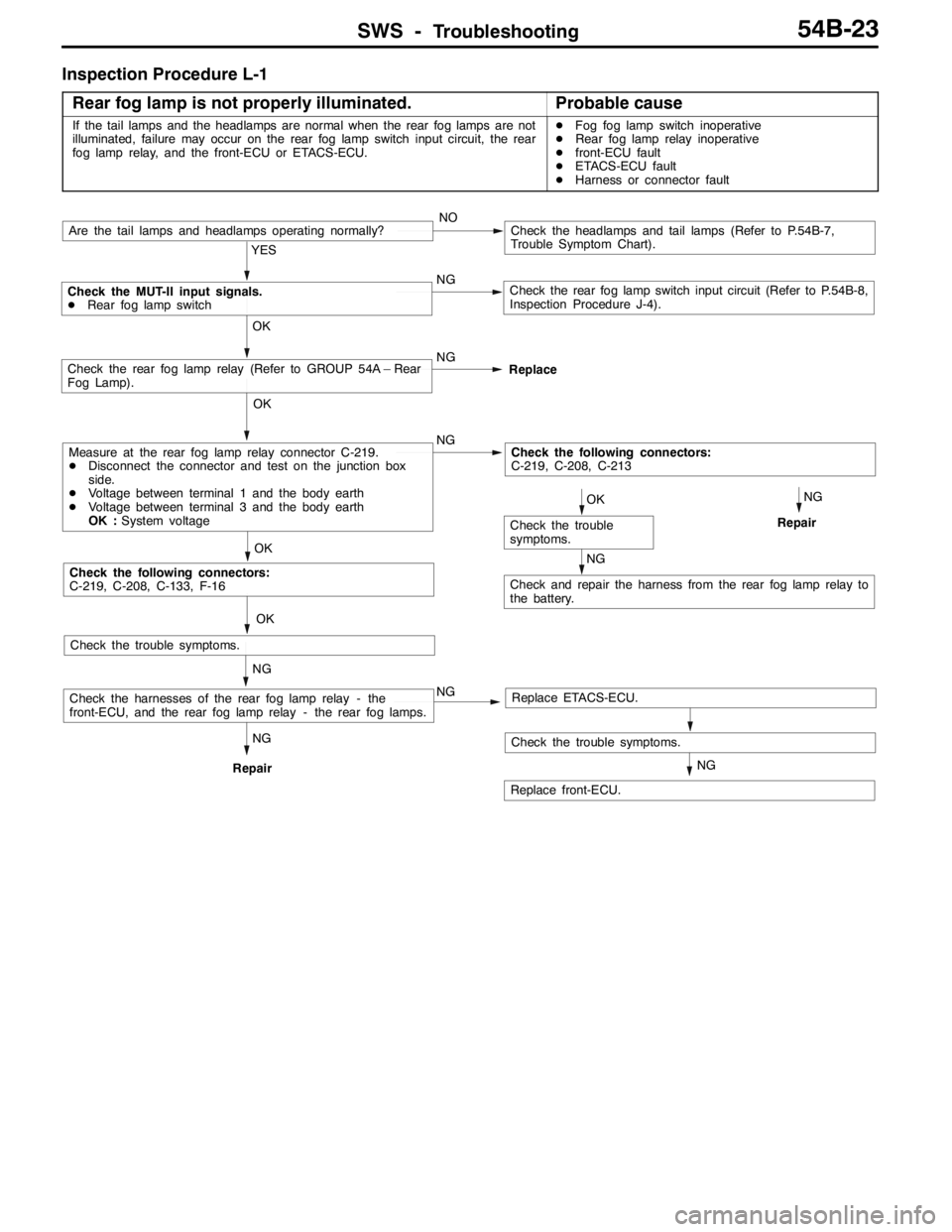
Inspection Procedure L-1
Rear fog lamp is not properly illuminated.
Probable cause
If the tail lamps and the headlamps are normal when the rear fog lamps are not
illuminated, failure may occur on the rear fog lamp switch input circuit, the rear
fog lamp relay, and the front-ECU or ETACS-ECU.DFog fog lamp switch inoperative
DRear fog lamp relay inoperative
Dfront-ECU fault
DETACS-ECU fault
DHarness or connector fault
Check the trouble symptoms.
NG
Repair
OK
Check the trouble symptoms.
YES
NG
Check the rear fog lamp switch input circuit (Refer to P.54B-8,
Inspection Procedure J-4).
Are the tail lamps and headlamps operating normally?NOCheck the headlamps and tail lamps (Refer to P.54B-7,
Trouble Symptom Chart).
OK
NG
Check the MUT-II input signals.
DRear fog lamp switch
Replace
OK
Check the rear fog lamp relay (Refer to GROUP 54A – Rear
Fog Lamp).
NGCheck the following connectors:
C-219, C-208, C-213
NG
Check and repair the harness from the rear fog lamp relay to
the battery.
OK
Check the trouble
symptoms.
Check the following connectors:
C-219, C-208, C-133, F-16
OK
Measure at the rear fog lamp relay connector C-219.
DDisconnect the connector and test on the junction box
side.
DVoltage between terminal 1 and the body earth
DVoltage between terminal 3 and the body earth
OK :System voltage
Replace ETACS-ECU.
NG
Replace front-ECU.
NG
RepairNG
NGCheck the harnesses of the rear fog lamp relay - the
front-ECU, and the rear fog lamp relay - the rear fog lamps.
Page 1396 of 1449
SWS -Troubleshooting54B-32
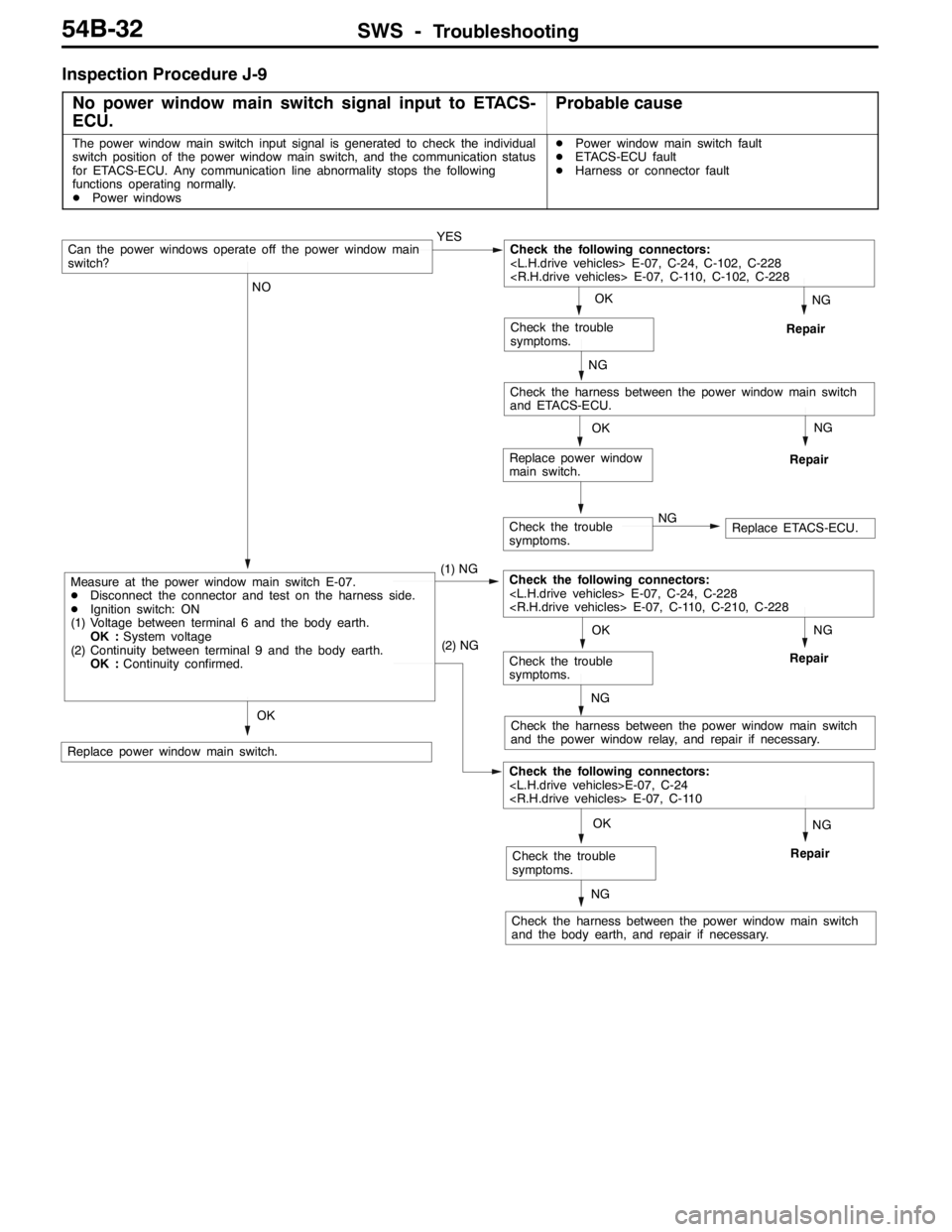
Inspection Procedure J-9
No power window main switch signal input to ETACS-
ECU.
Probable cause
The power window main switch input signal is generated to check the individual
switch position of the power window main switch, and the communication status
for ETACS-ECU. Any communication line abnormality stops the following
functions operating normally.
DPower windowsDPower window main switch fault
DETACS-ECU fault
DHarness or connector fault
Check the trouble
symptoms.NGReplace ETACS-ECU.
NG
Repair
NG
Repair
OK
Replace power window
main switch.
NG
Repair
NG
Check the harness between the power window main switch
and the power window relay, and repair if necessary.
NG
Repair
NG
Check the harness between the power window main switch
and the body earth, and repair if necessary.
OK
Replace power window main switch.
OK
Check the trouble
symptoms.
(2) NG
Check the following connectors:
OK
Check the trouble
symptoms.
NO
Measure at the power window main switch E-07.
DDisconnect the connector and test on the harness side.
DIgnition switch: ON
(1) Voltage between terminal 6 and the body earth.
OK :System voltage
(2) Continuity between terminal 9 and the body earth.
OK :Continuity confirmed.(1) NGCheck the following connectors:
NG
Check the harness between the power window main switch
and ETACS-ECU.
OK
Check the trouble
symptoms.
Can the power windows operate off the power window main
switch?YESCheck the following connectors:
Page 1398 of 1449

SWS -Troubleshooting54B-34
CHECKS AT ECU TERMINALS
ETACS-ECU
*
Y0795AU
NOTE
*See the list below for data on the ETACS-ECU terminal 1 - 20 connectors. As the ETACS-ECU connects
directly onto the junction box, the voltages cannot be measured.
Terminal
No.Check itemsChecking requirementsNormal condition
1Power window relay outputWhen power windows operating
normallySystem voltage
2Battery power supply (for central
locking)Any timeSystem voltage
3Earth (for ECU)Any time0V
4Ignition switch (ACC)Ignition switch: ACCSystem voltage
5Room lamp outputWhen room lamps ON2 V or below
6---
7Door switch inputWhen any one door switch ON (door
open)0V
8Ignition switch (IG1) power supplyIgnition switch: ONSystem voltage
9Right-hand turn signal lamp outputWhen right-hand turn signal lamp ONSystem voltage
10Driver’s door switch inputWhen driver’s door switch ON (door
open)0V
11Battery power supply (for hazard
lamps)Any timeSystem voltage
12Central locking (lock) outputWhen door lock actuator operating
(locking operation)System voltage
13Central locking (unlock) output (NOT
driver’s door)When door lock actuator operating
(unlocking)System voltage
14Left-hand turn signal lamp outputWhen left-hand turn signal lamp ONSystem voltage
15 - 17---
18Ignition switch (ACC) power supplyIgnition switch: ACCSystem voltage
19Battery power supply for interior lampWhen interior lamp ONSystem voltage
20Battery power supply (for ECU)Any timeSystem voltage
21Rear fog lamp switch inputWhen the rear fog lamp switch ON0V
22Central locking (unlock) output (for
driver’s door)When door lock actuator operating
(unlocking)System voltage
23---
24 - 32---
33Door lock key cylinder switch input
(unlock switch)When driver’s door lock unlocked0V
34Door lock key cylinder switch input
(lock switch)When driver’s door lock locked0V
Page 1400 of 1449

SWS -Troubleshooting54B-36
COLUMN SWITCHES
Terminal
No.Check itemChecking requirementsNormal condition
1Battery power supplyAny timeSystem voltage
2SWS request signal inputAny time0 - 12 V (pulse
signal)
3SWS communication lineAny time0 - 12 V (pulse
signal)
4EarthAny time0V
5-7---
8Windshield wiper switch backup
outputWindshield wiper low or high-speed
switch: ON0V
9Ignition switch (IG1) power supplyIgnition switch: ONSystem voltage
10Headlamp switch backup outputHeadlamp switch: ON0V
FRONT-ECU
NOTE
See the list below for data on the front-ECU terminals. As the front-ECU connects directly onto the relay
box, the voltages cannot be measured.
Terminal
No.Check itemChecking requirementsNormal condition
1---
2Headlamp (high-beam) outputWhen headlamp (high-beam) ONSystem voltage
3, 4Battery power supply (for headlamps)Any timeSystem voltage
5Battery power supply (for tail lamps)Any timeSystem voltage
6Headlamp (low-beam) outputWhen headlamp (low-beam) ONSystem voltage
7Battery power supply (for ECU)Any timeSystem voltage
8Tail lamp outputWhen tail lamps ONSystem voltage
9-11---
21Windshield washer outputWhen windshield washer operatingSystem voltage
22SWS communication lineAny time0 - 12 V (pulse
signal)
23Windshield wiper automatic STOP
signal inputWhen windshield wiper operatingSystem voltage
24Ignition switch (ACC) power supplyIgnition switch: ACCSystem voltage
25Headlamp switch backup inputHeadlamp switch: ON0V
26Windshield wiper switch backup inputWindshield wiper low or high-speed
switch: ON0V
27Windshield wiper (low-speed) outputWhen windshield wiper operating (at
low-speed)System voltage
28Windshield wiper (high-speed) outputWhen windshield wiper operating (at
high-speed)System voltage