sensor MITSUBISHI LANCER EVOLUTION 2007 Service Repair Manual
[x] Cancel search | Manufacturer: MITSUBISHI, Model Year: 2007, Model line: LANCER EVOLUTION, Model: MITSUBISHI LANCER EVOLUTION 2007Pages: 1449, PDF Size: 56.82 MB
Page 1084 of 1449

ABS <4WD> -Troubleshooting35B-14
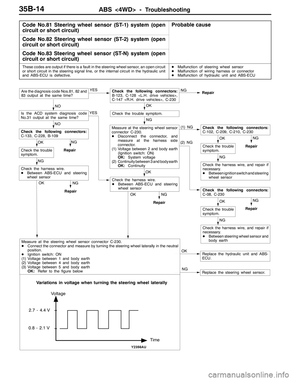
Code No.81 Steering wheel sensor (ST-1) system (open
circuit or short circuit)Probable cause
Code No.82 Steering wheel sensor (ST-2) system (open
circuit or short circuit)
Code No.83 Steering wheel sensor (ST-N) system (open
circuit or short circuit)
These codes are output if there is a fault in the steering wheel sensor, an open circuit
or short circuit in the steering signal line, or the internal circuit in the hydraulic unit
and ABS-ECU is defective.DMalfunction of steering wheel sensor
DMalfunction of wiring harness or connector
DMalfunction of hydraulic unit and ABS-ECU
NG
Repair
Replace the hydraulic unit and ABS-
ECU. OK NG YES
Repair
NOAre the diagnosis code Nos.81, 82 and
83 output at the same time?
OKCheck the following connectors:
B-123, C-128
C-147
YES
NO
Is the ACD system diagnosis code
No.31 output at the same time?
NG
Check the trouble symptom.
(1) NG
(2) NGNG
Repair
NG
OK
Check the trouble
symptom.
Check the following connectors:
C-102, C-209, C-210, C-230
Check the harness wire, and repair if
necessary.
DBetween ignition switch and steering
wheel sensor
NG
OK
Check the trouble
symptom.
Check the following connectors:
C-08, C-230
Check the harness wire, and repair if
necessary.
DBetween steering wheel sensor and
body earth
OK
Measure at the steering wheel sensor
connector C-230.
DDisconnect the connector, and
measure at the harness side
connector.
(1) Voltage between 2 and body earth
(Ignition switch: ON)
OK:System voltage
(2) Continuity between 3 and body earth
OK:Continuity
NG
RepairOK
Check the harness wire.
DBetween ABS-ECU and steering
wheel sensor NG
Repair
NG OK
Check the trouble
symptom.
Check the following connectors:
C-133, C-228, B-109
NG
Repair
Check the harness wire.
DBetween ABS-ECU and steering
wheel sensor
OK
Replace the steering wheel sensor. NG
Time Voltage
2.7 - 4.4 V
0.8 - 2.1 V
Variations in voltage when turning the steering wheel laterally
Measure at the steering wheel sensor connector C-230.
DConnect the connector and measure by turning the steering wheel laterally in the neutral
position.
DIgnition switch: ON
(1) Voltage between 1 and body earth
(2) Voltage between 4 and body earth
(3) Voltage between 5 and body earth
OK:Refer to the figure below
Page 1085 of 1449

ABS <4WD> -Troubleshooting35B-15
INSPECTION CHART FOR TROUBLE SYMPTOMS
Trouble symptomsInspection procedure
No.Reference page
Communication between the MUT-IIand the whole system is not
possible.135B-16
Communication between the MUT-IIand the ABS-ECU is not possible.235B-17
When the ignition key is turned to “ON” (engine stopped), the ABS
warning lamp does not illuminate.335B-18
Even after the engine is started, the ABS warning lamp remains
illuminated.435B-18
In the inspection with MUT-II service data, the parking brake switch is not
turned ON or turn OFF.535B-19
The neutral position learning of the steering wheel sensor is not finished.635B-20
Faulty ABS operation735B-21
Caution
1. If steering movements are made when driving at high speed, or when driving on road surfaces
with low frictional resistance, or when passing over bumps, the ABS may operate even though
sudden braking is not being applied. Because of this, when getting information from the customer,
check if the problem occurred while driving under such conditions as these.
2. During ABS operation, the brake pedal may vibrate or may not be able to be depressed. Such
phenomena are due to intermittent changes in hydraulic pressure inside the brake line to prevent
the wheels from locking and is not an abnormality.
Page 1090 of 1449

ABS <4WD> -Troubleshooting35B-20
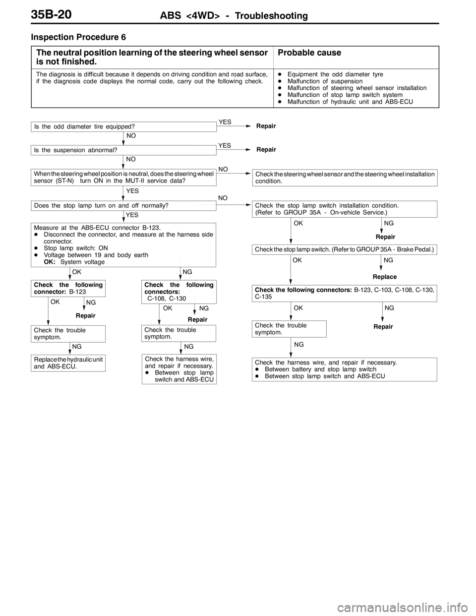
Inspection Procedure 6
The neutral position learning of the steering wheel sensor
is not finished.
Probable cause
The diagnosis is difficult because it depends on driving condition and road surface,
if the diagnosis code displays the normal code, carry out the following check.DEquipment the odd diameter tyre
DMalfunction of suspension
DMalfunction of steering wheel sensor installation
DMalfunction of stop lamp switch system
DMalfunction of hydraulic unit and ABS-ECU
NG
NG
NG
NG
Check the harness wire, and repair if necessary.
DBetween battery and stop lamp switch
DBetween stop lamp switch and ABS-ECU
OK
Check the trouble
symptom.
OK
Check the following connectors:B-123, C-103, C-108, C-130,
C-135
OK
Check the stop lamp switch. (Refer to GROUP 35A - Brake Pedal.)
Check the stop lamp switch installation condition.
(Refer to GROUP 35A - On-vehicle Service.) NO
Repair
OKNG
RepairOKNG
RepairReplace
NG
Replace the hydraulic unit
and ABS-ECU.
NG
Check the harness wire,
and repair if necessary.
DBetween stop lamp
switch and ABS-ECURepair
Check the trouble
symptom.
NG
Check the following
connectors:
C-108, C-130
Check the trouble
symptom.
OK
Check the following
connector:B-123
YES
Measure at the ABS-ECU connector B-123.
DDisconnect the connector, and measure at the harness side
connector.
DStop lamp switch: ON
DVoltage between 19 and body earth
OK:System voltage
Does the stop lamp turn on and off normally?
YES
Repair
NO
Is the odd diameter tire equipped?
YES
Repair
NO
Is the suspension abnormal?
NO
YES
When the steering wheel position is neutral, does the steering wheel
sensor (ST-N) turn ON in the MUT-II service data?Check the steering wheel sensor and the steering wheel installation
condition.
Page 1091 of 1449

ABS <4WD> -Troubleshooting35B-21
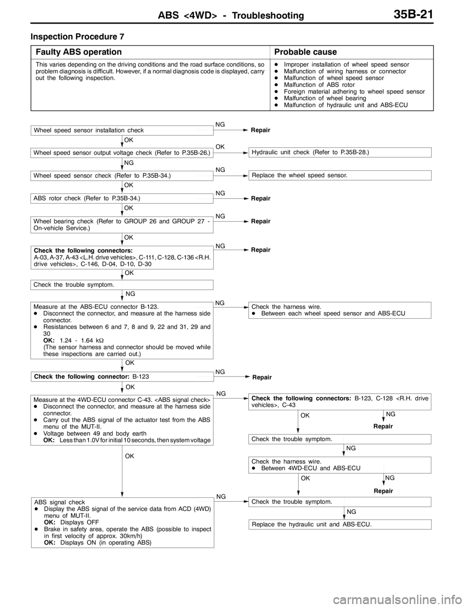
Inspection Procedure 7
Faulty ABS operation
Probable cause
This varies depending on the driving conditions and the road surface conditions, so
problem diagnosis is difficult. However, if a normal diagnosis code is displayed, carry
out the following inspection.DImproper installation of wheel speed sensor
DMalfunction of wiring harness or connector
DMalfunction of wheel speed sensor
DMalfunction of ABS rotor
DForeign material adhering to wheel speed sensor
DMalfunction of wheel bearing
DMalfunction of hydraulic unit and ABS-ECU
OK
OK
Check the following connector:B-123
NG
Measure at the ABS-ECU connector B-123.
DDisconnect the connector, and measure at the harness side
connector.
DResistances between 6 and 7, 8 and 9, 22 and 31, 29 and
30
OK:1.24 - 1.64 kΩ
(The sensor harness and connector should be moved while
these inspections are carried out.)NG
OK
Check the trouble symptom.
OK
NG
Repair
OK
Wheel bearing check (Refer to GROUP 26 and GROUP 27 -
On-vehicle Service.)NG
Repair
OK
ABS rotor check (Refer to P.35B-34.)NG
Repair
NG
Wheel speed sensor check (Refer to P.35B-34.)NGReplace the wheel speed sensor.
OK
Wheel speed sensor output voltage check (Refer to P.35B-26.)OKHydraulic unit check (Refer to P.35B-28.)
Wheel speed sensor installation checkNG
Repair
Check the harness wire.
DBetween each wheel speed sensor and ABS-ECU
NG
Repair
NG
NG
RepairOK
Check the following connectors:B-123, C-128
NG
Check the trouble symptom.
RepairNG
OK
Check the harness wire.
DBetween 4WD-ECU and ABS-ECU OK
Measure at the 4WD-ECU connector C-43.
DDisconnect the connector, and measure at the harness side
connector.
DCarry out the ABS signal of the actuator test from the ABS
menu of the MUT-II.
DVoltage between 49 and body earth
OK:Less than 1.0V for initial 10 seconds, then system voltage
NGABS signal check
DDisplay the ABS signal of the service data from ACD (4WD)
menu of MUT-II.
OK:Displays OFF
DBrake in safety area, operate the ABS (possible to inspect
in first velocity of approx. 30km/h)
OK:Displays ON (in operating ABS)
NG
Check the trouble symptom.
Replace the hydraulic unit and ABS-ECU.
Check the following connectors:
A-03, A-37, A-43
Page 1092 of 1449

ABS <4WD> -Troubleshooting35B-22
DATA LIST REFERENCE TABLE
The following items can be read by the MUT-IIfrom the ABS-ECU input data.
1. When the system is normal
Item No.Check itemChecking requirementsNormal value
11Front-right wheel speed sensorPerform a test runVehicle speeds
displayedonthe
12Front-left wheel speed sensor
displayedonthe
speedometer and
MUTIIareidentical13Rear-right wheel speed sensorMUT-IIareidentical.
14Rear-left wheel speed sensor
21Power supply voltageIgnition switch: ON10 - 16 V
29Parking brake switchPull the parking brake lever.ON
Release the parking brake lever.OFF
36Stop lamp switchDepress the brake pedal.ON
Release the brake pedal.OFF
37Steering wheel sensor neutral
position learningAfter driving straightly with vehicle speed more
than 10km/hON
Before driving with ignition switch ONOFF
71Lateral G sensorWhen vehicle stops2.4 - 2.6 V
When vehicle drives1.0 - 4.0 V
74Steering wheel sensor (ST-N)Ignition switch: ONSteering:
Neutral position and
position near by±
360_ON
Steering:
Except for aboveOFF
75Steering wheel sensor (ST-1)Ignition switch: ONSteering:
Turnlaterallyslowly
Display ON and OFF
alternately
76Steering wheel sensor (ST-2)
Turnlaterallyslowlyalternately
86Steering degreeIgnition switch: ON
Steering wheel sensor
tlitili
Steering: Steer by
90_to the right+90_
g
neutral position learning
is finished (service data
N37di lON)
Steering: NeutralOFF(
No. 37 displays ON)Steering: Steer by
90_to the left-90_
2. When the ABS-ECU shut off ABS operation
When the diagnosis system stops the ABS-ECU, the MUT-IIdisplay data will be unreliable.
Page 1094 of 1449

ABS <4WD> -Troubleshooting35B-24
CHECK AT ABS-ECU
Use the following steps to remove the connector cover and
measure the terminal voltage.
1. Move the lock lever of the ABS-ECU connector as shown
in the illustration, and then disconnect the ABS-ECU
connector.
2. Push up and unlock the hooks of the ABS-ECU connector
shown in the illustration, then remove the connector cover.
TERMINAL VOLTAGE CHECK CHART
1. Measure the voltage between each terminal and earth
(terminal No.12).
2. The terminal layout is shown in the illustration.
Terminal No.Check itemChecking requirementsNormal condition
1Parking brake switch
input
Parking brake switch: ON1 V or less
input
Parking brake switch: OFFSystem voltage
2MUT-IIWhen the MUT-IIis connectedSerial communication with MUT-II
When the MUT-IIis not connected1 V or less
3ABS ON output to
4WD ECU
With ABS active (reference)(0.5 V or less)
4WD-ECU
With ABS not activeSystem voltage
4Steering wheel sensor
(ST-N) inputIgnition
switch: ONSteering wheel: Neutral
position and position
near by±360_0.8 - 2.1 V
Steering wheel: Except
for above2.7 - 4.4 V
5Diagnosis changeover
input
When the MUT-IIis connected0V
input
When the MUT-IIis not connectedApprox. 12 V
Lock lever
Page 1095 of 1449

ABS <4WD> -Troubleshooting35B-25
Terminal No. Normal conditionChecking requirements Check item
10ABS-ECU power
supply
Ignition switch: ONSystem voltage
supply
Ignition switch: START or ACC0V
11Solenoid valve power
supplyAlwaysSystem voltage
14Lateral G sensor inputIgnition switch: ON2.4 - 2.6 V (horizontal position)
15Longitudinal G sensor
earthAlways0V
17Steering wheel sensor
(ST-2) inputIgnition
switch: ONSteering wheel: Turn
laterallyVariation in the voltage value 0.8 -
2.1 V and 2.7 - 4.4 V
18Wheel speed sensor
(front right) outputMoving forward slowly0-5V
19Stop lamp monitor
input
Ignition
switch:ON
Stop lamp switch: ONSystem voltage
inputswitch:ON
Stop lamp switch: OFF1 V or less
20Wheel speed sensor
(rear left) outputMoving forward slowly0-5V
21Wheel speed sensor
(rear right) outputMoving forward slowly0-5V
24Lateral G sensor earthAlways0V
25Longitudinal G sensor
inputIgnition switch: ON2.4 - 2.6 V (horizontal position)
26Steering wheel sensor
(ST-1) inputIgnition
switch: ONSteering wheel: Turn
laterallyVariation in the voltage value 0.8 -
2.1 V and 2.7 - 4.4 V
27ABS warning lamp
transistor outputIgnition
switch: ONWhen the lamp is
switched off1 V or less
When the lamp is
illuminated7 V or more
32Wheel speed sensor
(front left) outputMoving forward slowly0-5V
33Motor power supplyAlwaysSystem voltage
Page 1096 of 1449

ABS <4WD> -Troubleshooting/On-vehicle Service35B-26
RESISTANCE AND CONTINUITY BETWEEN
HARNESS-SIDE CONNECTOR TERMINALS
1. Turn the ignition key to the “LOCK” (OFF) position.
2. Disconnect the ABS-ECU connector.
3. Check the resistance and continuity between the terminals
indicated in the table below.
4. The terminal layout is shown in the illustration.
ABS-ECU terminal No.SignalNormal condition
6-7Wheel speed sensor (rear left)1.24 - 1.64 kΩ
8-9Wheel speed sensor (rear right)
22 - 31Wheel speed sensor (front left)
29 - 30Wheel speed sensor (front right)
12 - Body earthEarthContinuity
34 - Body earthEarth
ON-VEHICLE SERVICE
WHEEL SPEED SENSOR OUTPUT VOLTAGE
CHECK
1. Lift up the vehicle and release the parking brake.
2. Move the lock lever of the ABS-ECU connector as shown
in the illustration, and then disconnect the ABS-ECU
connector.
3. Push up and unlock the hooks of the ABS-ECU connector
shown in the illustration, then remove the connector cover.
Lock lever
Page 1097 of 1449

ABS <4WD> -On-vehicle Service35B-27
4. Rotate the wheel to be measured at approximately 1/2 - 1
rotation per second, and check the output voltage using a
circuit tester or an oscilloscope.
Wheel speed
sensorFront
leftFront
rightRear
leftRear
right
Terminal No.222968
313079
Output voltage
When measuring with a circuit tester:
42 mV or more
When measuring with an oscilloscope:
120 mV p-p or more
5. The followings are suspected if the output voltage is lower
than the value described above. Check the wheel speed
sensor, and replace if necessary.
DToo large clearance between the pole piece of the
wheel speed sensor and ABS rotor
DFaulty wheel speed sensor
Inspecting Waveforms With An Oscilloscope
Use the following method to observe the output voltage
waveform from each wheel speed sensor with an oscilloscope.
DStart the engine, and rotate the front wheels by engaging
1st gear. Turn the rear wheels manually so that they
rotate at a constant speed.
NOTE
1. The waveform measurements can also be taken while
the vehicle is actually moving.
2. The output voltage will be small when the wheel speed
is low, and similarly it will be large when the wheel speed
is high.
Points In Waveform Measurement
SymptomProbable causesRemedy
Too small or zero waveform
amplitudeFaulty wheel speed sensorReplace sensor
Waveform amplitude fluctuates
excessivel
y(this is noproblem if
Axle hub eccentric or with large runoutReplace hub
excessively(thisisnoproblemif
the minimum amplitude is 100 mV
or more)Faulty ABS-ECU earthRepair
When turning by hand
When idling (5 - 6 km/h), 1st gear
10.0 ms/DIV 1 V/DIV
Page 1098 of 1449

ABS <4WD> -On-vehicle Service35B-28
SymptomRemedy Probable causes
Noisy or disturbed waveformOpen circuit in sensorReplace sensor
Open circuit in harnessCorrect harness
Incorrectly mounted wheel speed sensorMount correctly
ABS rotor with missing or damaged teethReplace ABS rotor
Caution
Because the wheel speed sensor cables move together with the front and rear suspension, they
vibrate greatly when driving over poor road surfaces. As a result, the sensor harnesses should also
be shaken when monitoring of output waveforms of the wheel speed sensors in order to simulate
conditions such as driving over poor road surfaces.
HYDRAULIC UNIT CHECK
1. Jack up the vehicle and support the vehicle with rigid racks placed at the specified jack-up points
or place the wheels which are checked on the rollers of the braking force tester.
Caution
(1) The roller of the braking force tester and the tyre should be dry during testing.
(2) When testing the front brakes, apply the parking brake, and when testing the rear brakes,
stop the front wheels by chocking them.
2. Turn the ignition key to the “LOCK” (OFF) position and set the MUT-II.
Caution
Turn the ignition key to the “LOCK” (OFF) position before connecting or disconnecting the
MUT-II.
3. After checking that the shift lever is in neutral, start the engine.
4. Use the MUT-IIto force-drive the actuator.
NOTE
(1) During the actuator test, the ABS warning lamp will illuminate and the anti-skid control will be
cancelled.
(2) When the ABS has been interrupted by the fail-safe function, the MUT-IIactuator testing cannot
be carried out.
5. Turn the wheel by hand and check the change in braking force when the brake pedal is depressed.
When using the braking force tester, depress the brake pedal until the braking force is at the following
values, and check that the braking force decreases when the actuator is force-driven.
Front wheel785 - 981 N
Rear wheel588 - 784 N