sensor MITSUBISHI LANCER EVOLUTION 2007 Service Repair Manual
[x] Cancel search | Manufacturer: MITSUBISHI, Model Year: 2007, Model line: LANCER EVOLUTION, Model: MITSUBISHI LANCER EVOLUTION 2007Pages: 1449, PDF Size: 56.82 MB
Page 1103 of 1449

ABS <4WD> -Wheel Speed Sensor35B-33
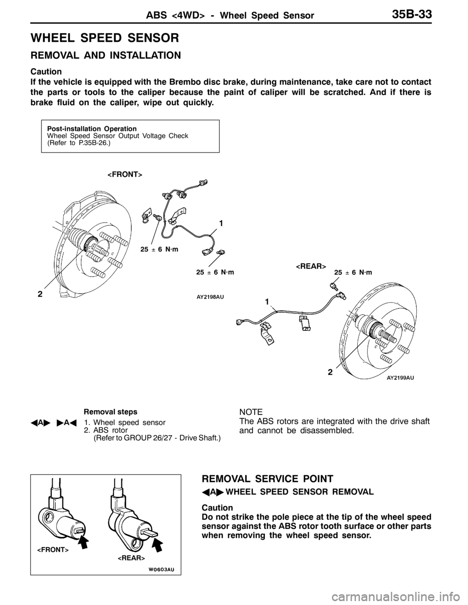
WHEEL SPEED SENSOR
REMOVAL AND INSTALLATION
Caution
If the vehicle is equipped with the Brembo disc brake, during maintenance, take care not to contact
the parts or tools to the caliper because the paint of caliper will be scratched. And if there is
brake fluid on the caliper, wipe out quickly.
Post-installation Operation
Wheel Speed Sensor Output Voltage Check
(Refer to P.35B-26.)
1
2
1
2
25±6 N·m
25±6 N·m25±6 N·m
Removal steps
AA""AA1. Wheel speed sensor
2. ABS rotor
(Refer to GROUP 26/27 - Drive Shaft.)NOTE
The ABS rotors are integrated with the drive shaft
and cannot be disassembled.
REMOVAL SERVICE POINT
AA"WHEEL SPEED SENSOR REMOVAL
Caution
Do not strike the pole piece at the tip of the wheel speed
sensor against the ABS rotor tooth surface or other parts
when removing the wheel speed sensor.
Page 1104 of 1449

ABS <4WD> -Wheel Speed Sensor35B-34
INSTALLATION SERVICE POINT
"AAWHEEL SPEED SENSOR
INSTALLATION
Install the wheel speed sensor crossing with the parking brake
cable.
INSPECTION
CHECK OF RESISTANCE BETWEEN WHEEL SPEED
SENSOR TERMINALS
Caution
The pole piece can become magnetized because of the
magnet built into the wheel speed sensor, with the result
that metallic foreign material easily adheres to it.
Moreover, the pole piece may not be able to function to
correctly sense the wheel rotation speed if it is damaged.
1. Measure the resistance between the wheel speed sensor
terminals.
Standard value: 1.24 - 1.64 kΩ
If the internal resistance of the wheel speed sensor is
not within the standard value, replace with a new wheel
speed sensor.
2. Check the wheel speed sensor cable for breakage,
damage or disconnection; replace with a new one if a
problem is found.
NOTE
When checking for cable damage, remove the cable clamp
part from the body and then bend and pull the cable
near the clamp to check whether or not temporary
disconnection occurs. Also check the connection of the
connector and that the terminals are inserted correctly.
ABS ROTOR CHECK
Check whether ABS rotor teeth are broken or deformed, and,
if so, replace the ABS rotor.
WHEEL SPEED SENSOR INSULATION INSPECTION
1. Remove all connections from the wheel speed sensor,
and then measure the resistance between terminal 1 and
the body of the wheel speed sensor, and terminal 2 and
the body of the wheel speed sensor.
Standard value: 100 kΩor more
2. If the speed sensor insulation resistance is outside the
standard value range, replace with a new speed sensor.
Wheeel speed sensor
Parking brake cable
Page 1105 of 1449

ABS <4WD> -G Sensors and Steering Wheel Sensor35B-35
G SENSORS AND STEERING WHEEL
SENSOR
REMOVAL AND INSTALLATION
Refer to GROUP 22 - Sensor, Switch and Relay.
Parking brake lever
Lateral G sensorLongitudinal G sensor
Steering wheel sensor
Page 1246 of 1449

SRS -General InformationSRS -General Information52B-2
GENERAL INFORMATION
To improve safety, the SRS and seat belts with
pre-tensioner. These systems enhance collision
safety by restraining the front passengers in case
of an accident. The SRS works with the
pre-tensioner simultaneously when a collision is
detected.
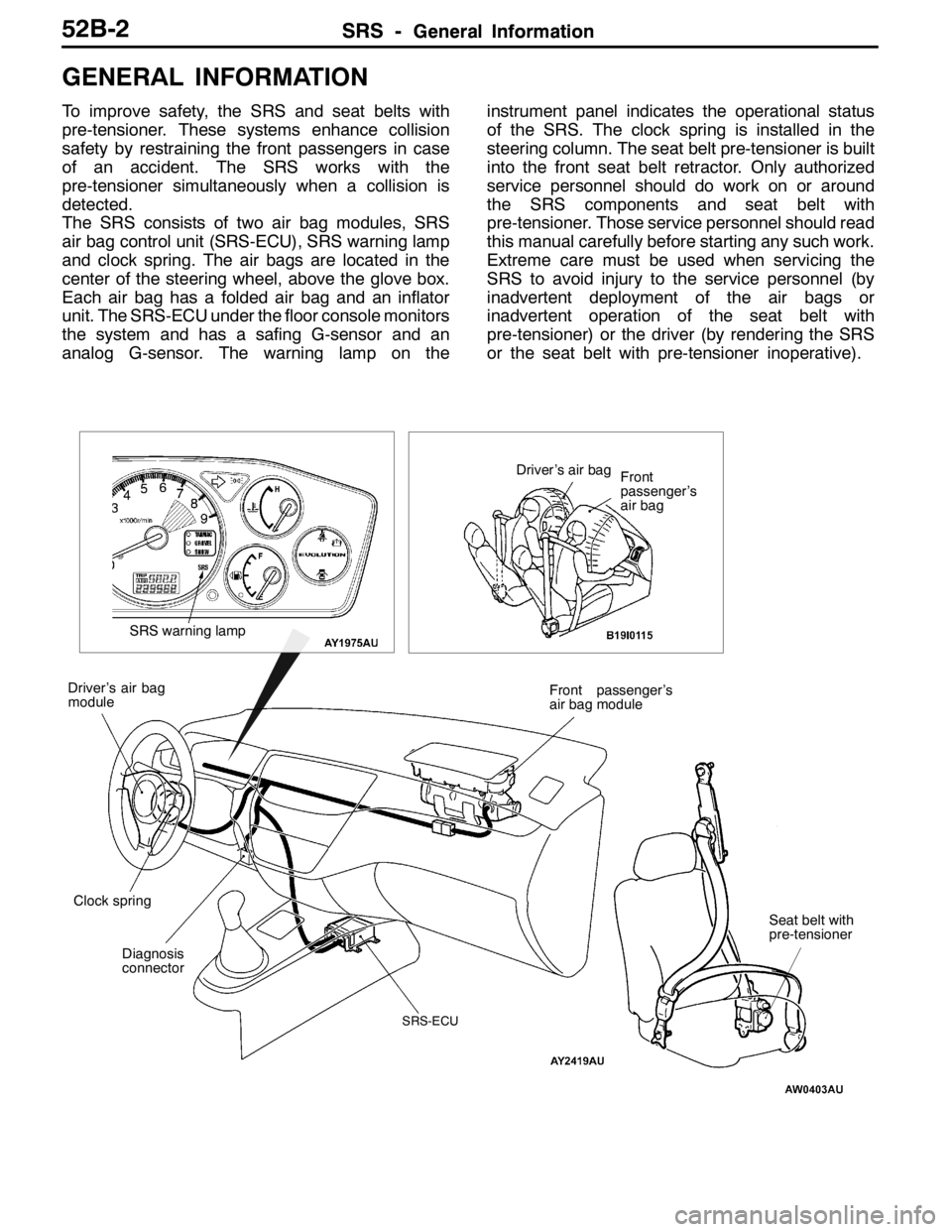
The SRS consists of two air bag modules, SRS
air bag control unit (SRS-ECU), SRS warning lamp
and clock spring. The air bags are located in the
center of the steering wheel, above the glove box.
Each air bag has a folded air bag and an inflator
unit. The SRS-ECU under the floor console monitors
the system and has a safing G-sensor and an
analog G-sensor. The warning lamp on theinstrument panel indicates the operational status
of the SRS. The clock spring is installed in the
steering column. The seat belt pre-tensioner is built
into the front seat belt retractor. Only authorized
service personnel should do work on or around
the SRS components and seat belt with
pre-tensioner. Those service personnel should read
this manual carefully before starting any such work.
Extreme care must be used when servicing the
SRS to avoid injury to the service personnel (by
inadvertent deployment of the air bags or
inadvertent operation of the seat belt with
pre-tensioner) or the driver (by rendering the SRS
or the seat belt with pre-tensioner inoperative).
Diagnosis
connectorFront passenger’s
air bag module
Clock spring Driver’s air bag
module
SRS-ECU
SRS warning lamp
Driver’s air bag
Front
passenger’s
air bag
Seat belt with
pre-tensioner
Page 1253 of 1449

SRS -Troubleshooting52B-9
WARNING LAMP CIRCUIT CONNECTOR LOCK SWITCH
Mechanism to automatically short-circuit the power supply
terminal and the earth terminal of the warning lamp circuit
when the SRS-ECU connector is disconnected. The structure
is the same as that of squib circuit connector lock switch.
INSPECTION CHART FOR DIAGNOSIS CODES
Inspect according to the inspection chart that is appropriate for the malfunction code.
Code no.Diagnostic itemPage
14SRS-ECU front impact analog G-sensor system52B-11
15SRS-ECU front impact safing G-sensor systemShort circuit in the
sensor52B-11
16SRS-ECU front impact safing G-sensor systemOpen circuit in the
sensor
21*1Driver’s air bag module (squib) systemShort circuit between
terminals of the squib
circuit52B-12
22*1Driver’s air bag module (squib) systemOpen in the squib
circuit52B-16
24*1Front passenger’s air bag module (squib) systemShort circuit between
terminals of the squib
circuit52B-20
25*1Front passenger’s air bag module (squib) systemOpen in the squib
circuit52B-22
26*1Driver’s seat belt pre-tensioner (squib) systemShort circuit between
terminals of the squib
circuit52B-23
27*1Driver’s seat belt pre-tensioner (squib) systemOpen in the squib
circuit52B-25
28*1Front passenger’s seat belt pre-tensioner (squib) systemShort circuit between
terminals of the squib
circuit52B-26
29*1Front passenger’s seat belt pre-tensioner (squib) system/Open in the squib
circuit52B-28
31SRS-ECU DC-DC converter systemIncreased terminal
voltage52B-11
32SRS-ECU DC-DC converter systemDecreased terminal
voltage
Ignition switch (IG1)
SRS warning lamp
SRS-ECU harness
side connector
Short spring
ON
ONOFF
OFF Connector*
lock switch
NOTE
*:connector engaged:ON
connector disengaged:OFF
Page 1255 of 1449

SRS -Troubleshooting52B-11
INSPECTION PROCEDURE CLASSIFIED BY DIAGNOSIS CODE
Code No.14, 15, 16, 31, 32, 45, 51, 52, 54, 55, 56, 57, 58, 59
System inside SRS-ECUProbable cause
Malfunction is present inside SRS-ECU. See table below for what each code
tells.DMalfunction of SRS-ECU
Code No.Defective partsTrouble
14Front impact analog G-sensorDNot operating
DAbnormal characteristics
DAbnormal output
15Front impact safing G-sensorDShort in the circuit
16DOpen in the circuit
31DC-DC converterDTerminal voltage of the converter higher than specified for
five seconds or more
32DTerminal voltage of the converter lower than specified for
5 seconds or more (this code is not detected when code
No.41 or 42, which indicates discharged battery, has been
detected)
45Non-volatile memory (EEPROM)DDefective parts inside
51Driver’sairbagmodule(squib)DShortinthecircuit51Driver’sairbag module(squib)
ignitiondrivecircuit
DShortinthecircuit
52ignition drive circuitDOpen in the circuit
54Front passenger’s air bag module
(squib)ignitiondrivecircuit
DShort in the circuit
55(squib)ignitiondrive circuitDOpen in the circuit
56Driver’s seat belt pre-tensioner
(squib)ignitiondrivecircuit
DShort in the circuit
57(squib)ignitiondrive circuitDOpen in the circuit
58Front passenger’s seat belt pre-ten-
sioner(squib)ignitiondrivecircuit
DShort in the circuit
59sioner(squib)ignitiondrive circuitDOpen in the circuit
If the above - mentioned code No. is output, replace the SRS-ECU.
Page 1293 of 1449

SRS - Individual Component Service/Warning/Caution Labels52B-49
INDIVIDUAL COMPONENT SERVICE
If the SRS components and seat belt with pre-tensioner are to be removed or replaced as a result of
maintenance, troubleshooting etc., follow the service procedures that follow.
Caution
1. SRS components and seat belt with pre-tensioner should not be subjected to heat, so remove
the SRS-ECU, driver’s air bag module
passenger’s air bag module, clock spring, and seat belt with pre-tensioner before drying or
baking the vehicle after painting.
DFront impact sensor, SRS-ECU, Air bag module, clock spring: 93_C or more
DSeat belt with pre-tensioner: 90_C or more
Recheck SRS system operability after re-installing them.
2. If the SRS components and seat belt with pre-tensioner are removed for the purpose of check,
sheet metal repair, painting, etc., they should be stored in a clean, dry place until they are
reinstalled.
WARNING/CAUTION LABELS
Caution labels on the SRS are attached in the
vehicle as shown. Follow label instructions whenservicing the SRS. If the label(s) are dirty or
damaged, replace with new one(s).
Steering wheel
Driver’s air bag module
Clock springFront passenger’s
air bag moduleSRS-ECU
Sun visor
Steering joint cover
Glove boxCover
Seat belt with pre-tensioner
Page 1380 of 1449

SWS -Troubleshooting54B-16
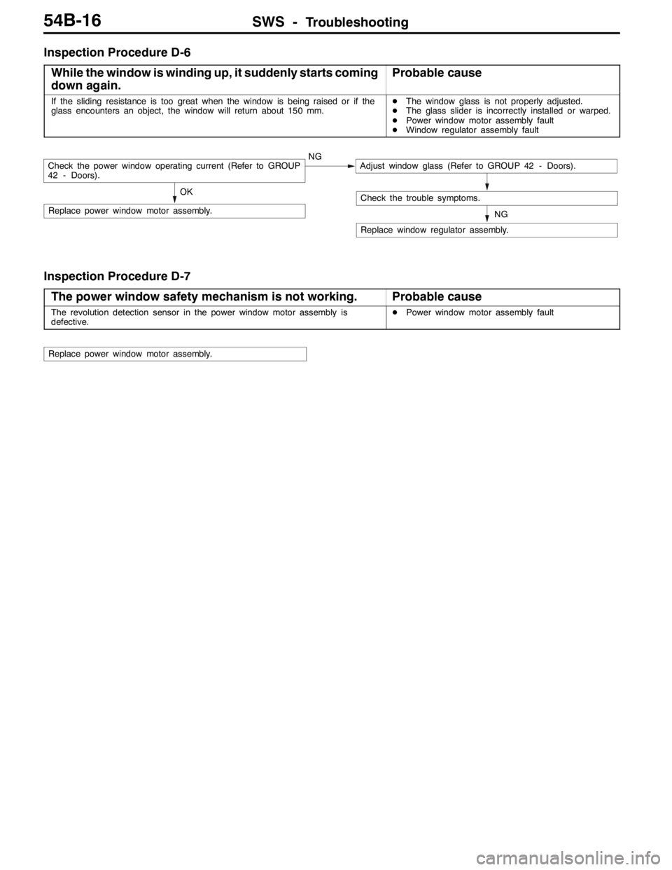
Inspection Procedure D-6
While the window is winding up, it suddenly starts coming
down again.
Probable cause
If the sliding resistance is too great when the window is being raised or if the
glass encounters an object, the window will return about 150 mm.DThe window glass is not properly adjusted.
DThe glass slider is incorrectly installed or warped.
DPower window motor assembly fault
DWindow regulator assembly fault
NG
Replace window regulator assembly.
OK
Replace power window motor assembly.
Check the trouble symptoms.
Check the power window operating current (Refer to GROUP
42 - Doors).NGAdjust window glass (Refer to GROUP 42 - Doors).
Inspection Procedure D-7
The power window safety mechanism is not working.
Probable cause
The revolution detection sensor in the power window motor assembly is
defective.DPower window motor assembly fault
Replace power window motor assembly.
Page 1399 of 1449

SWS -Troubleshooting54B-35
Terminal
No.Normal condition Checking requirements Check items
35Driver’s door lock actuator (locking
switch) inputWhen driver’s door lock locked0V
36Driver’s door lock actuator (unlocking
switch) inputWhen driver’s door lock unlocked0V
37, 38---
39Back-up lamp switch inputWhen shift lever in reverse positionSystem voltage
40---
51Diagnosis output/input check signal
outputDuring diagnosis output (when MUT-II
connected or diagnosis connector No. 1
grounded on the body.)0 - 12 V (pulse
signal)
When an input check is output0, 12 V (at input
signal change)
52Ignition switch (ACC) power supplyIgnition switch: ACCSystem voltage
53, 54---
55Hazard warning lamp switch inputHazard warning lamp switch: ON0V
56Earth (for sensors)Any time0V
57, 58---
59SWS communication lineAny time0 - 12 V (pulse
signal)
60---
61Battery power supplyAny timeSystem voltage
62---
63Vehicle speed signal inputWhen vehicle driven0 - 12 V (pulse
signal)
64 - 66---
67Diagnosis control inputWhen MUT-II connected0V
68SWS request signal outputAny time0 - 12 V (pulse
signal)
69Ignition key cylinder illumination lamp
outputWhen ignition key cylinder illumination
lamp ON2 V or below
70---
71 - 73---
74Rear fog lamp output
Page 1403 of 1449

55-1
HEATER, AIR
CONDITIONER AND
VENTILATION
CONTENTS
SERVICE SPECIFICATIONS 2.................
LUBRICANTS 2..............................
SPECIAL TOOLS 2...........................
TROUBLESHOOTING 3.......................
ON-VEHICLE SERVICE 14....................
Refrigerant Level Test through Performance Test 14.
Magnetic Clutch Test 14.........................
Receiver Drier Test 14..........................
Compressor Drive Belt Adjustment 15.............
Dual Pressure Switch Check 15..................
Charging 16...................................
Correcting Low Refrigerant Level in case the Service
can used 18...................................
Discharging System 19..........................
Refilling of Oil in the A/C System 19...............
Performance Test 20............................
Refrigerant Leak Repair 21......................
Blower Relay Continuity Check 22................
A/C Compressor Relay Continuity Check 22........Condenser Fan Relay (LO) Check 23.............
Condenser Fan Relay (HI) Check 23..............
Idle-up Operation Check 24.....................
HEATER CONTROL ASSEMBLY (A/C-ECU)
AND A/C SWITCH 25........................
HEATER UNIT AND BLOWER ASSEMBLY 28.
REGISTOR, BLOWER MOTOR AND
INSIDE/OUTSIDE AIR CHANGE OVER
DAMPER MOTOR 32.........................
EVAPORATOR AND AIR THERMO SENSOR
34 ...........................................
COMPRESSOR 36............................
CONDENSER ASSEMBLY AND CONDENSER
FAN ASSEMBLY 40...........................
REFRIGERANT LINES 42.....................
DUCTS 44...................................
VENTILATION 45.............................