headlamp MITSUBISHI LANCER EVOLUTION 2007 Service Owner's Manual
[x] Cancel search | Manufacturer: MITSUBISHI, Model Year: 2007, Model line: LANCER EVOLUTION, Model: MITSUBISHI LANCER EVOLUTION 2007Pages: 1449, PDF Size: 56.82 MB
Page 202 of 1449

CIRCUIT DIAGRAMSB-104
HEADLAMP
Page 204 of 1449

CIRCUIT DIAGRAMS
H1J08X19AA
B-106
HEADLAMP
R.H. drive vehicles
Page 206 of 1449

CIRCUIT DIAGRAMS
H1J08X19BA
B-108
HEADLAMP
Page 228 of 1449

CIRCUIT DIAGRAMSB-130
HEADLAMP LEVELING SYSTEM
L.H. drive vehicles
Page 230 of 1449

CIRCUIT DIAGRAMSB-132
HEADLAMP LEVELING SYSTEM
R.H. drive vehicles
Page 357 of 1449

INDEX - In order of connector No.C-1
INDEX
In order of connector No.
Connector
No.Parts nameCircuit diagram pageWiring diagram
page
AA-01Side turn signal lamp (RH)B-135,139B-6,8
A-02Side turn signal lamp (LH)B-134,138B-6,8
A-03Wheel speed sensor (Front:LH)B-203,211,217,225,233,243B-6,8
A-04XSpare connector (for front fog lamp
relay)B-73,258B-6,8
A-05XHorn relayB-73,146B-6,8
A-06XCondenser fan relay (LO)B-73,177,183B-6,8
A-07XCondenser fan relay (HI)B-73,177,183B-6,8
A-08XNo connectionB-73B-6,8
A-09XRadiator fan relayB-73,102,176,182B-6,8
A-10XFront-ECUB-73,75,103,104,106,107,110,111,
114,115,124,127,130,131,132,133,
136,140,187,191, 258B-6,8
A-11XFront-ECUB-73,104,106,107,111,115,124,127,
131,133, 136,140,186,187,190,191B-6,8
A-12Front wiring harness (LH) and control
wiring harness combination
A-13Front wiring harness (LH) and control
wiring harness combination
A-16Headlamp (HI:LH)B-103,106B-6,8
A-21Fan controllerB-102,176,182B-7,8
A-23Horn (HI)B-146B-7,8
A-25Horn (LO)B-146B-7,9
A-28Headlamp (HI:RH)B-103,106B-7,9
A-31Spare connector (for front fog lamp)B-258B-7,9
A-34No connection-B-9
A-36Dual pressure switchB-178,184B-7,9
A-37Wheel speed sensor (Front:RH)B-203,211,217,225,233,243B-7,9
A-39Front combination lamp (LH)B-103,106,110,114,130,132,134,138B-7,9
A-40Front combination lamp (RH)B-103,106,111,114,130,132,135,139B-7,9
A-43Front wiring harness (LH) and control
wiring harness combination
A-44Intercooler water spray motorB-256B-7,9
Page 360 of 1449

INDEX - In order of connector No.C-4
Wiring diagram
page Circuit diagram page Parts name Connector
No.
CC-10Outside/Inside air selection damper
control motor and potentiometerB-175,181B-18,24
C-14Blower motorB-174,180B-18,24
C-16ResistorB-174,180B-18,24
C-21SRS-ECUB-248,249,250,251B-18,24
C-22Diagnosis connectorB-92,100,105,108,113,117,119,123,
125,128,137,141,150,154,158,164,
170,172,188,189,204,205,219,227,
237,247,248,250,252,254B-18,24
C-23Diagnosis connectorB-92,100B-18,24
C-24Instrument panel wiring harness and
front door wiring harness (LH) combina-
tionB-162,163,165,170,172,173,192,193,
196B-18,24
C-26J/C (4)B-59,65,92,100,105,113,119,137,157,
158,170,188,194,197,201,204,205,
209,213,219,221,227,232,237,242,
247,250,252,254,258B-19,25
C-28J/C (5)
173,189,205,227,247,254B-25
C-29J/C (5)
157,187,194,197,198,214,230,248,
256B-19
C-32A/C-ECU or heater control unitB-175,181,185B-19,25
C-34No connection
C-35Instrument panel wiring harness and
instrument panel wiring harness com-
bination
154,164,165,172,180,185,189,205,
227,247,250,254B-25
C-36Headlamp leveling switchB-131,133B-19,25
C-41SRS-ECUB-249,251B-19,25
C-42Instrument panel wiring harness and
control wiring harness combination
C-434WD-ECU
219,220,221,222,223,224,226,227,
228,230,231,232,234,236,237,238,
240,241,242,244, 246,247B-19,25
C-444WD-ECU
221,224,225,227,228,229,232,234,
235,237,238,239,242,244,245,247B-19,25
C-45Instrument panel wiring harness and
floor wiring harness (LH) combination
Page 371 of 1449

INDEX - In order of parts nameC-15
Wiring diagram
page Circuit diagram page Connector
No. Parts name
GG sensor (Lateral)D-33B-200,208,213,221,229,239B-31,33
G sensor (Longitudinal)D-32B-200,208,213,221,229,239B-31,33
HHazard warning switchC-03B-136,140B-18,24
Headlamp (HI:LH)A-16B-103,106B-6,8
Headlamp (HI:RH)A-28B-103,106B-7,9
Headlamp leveling switchC-36B-131,133B-19,25
High mounted stop lampF-05B-144,145B-38,39
Horn (HI)A-23B-146B-7,8
Horn (LO)A-25B-146B-7,9
Horn relayA-05XB-73,146B-6,8
Horn switch
IIdle speed control servoB-115B-88,96B-12,16
Ignition coil 1B-114B-82,83B-12,16
Ignition coil 2B-119B-82,83B-12,16
Ignition coil relay
connection
Ignition switchC-201B-76B-22,28
Injector 1B-27B-89,97B-11,15
Injector 2B-26B-89,97B-11,15
Injector 3B-25B-89,97B-11,15
Injector 4B-24B-89,97B-11,15
Instrument panel wiring harness and
A/C wiring harness combinationC-107B-175,181B-20,26
Instrument panel wiring harness and
console wiring harness combinationD-15B-195B-31,32
Instrument panel wiring harness and
control wiring harness combinationC-128B-153,181,184,198,200,202,203,205,
206,208,209,211,213,214,216,217,
218,229,230,233,234,235,236,239,
242,243B-21,26
Instrument panel wiring harness and
control wiring harness combinationC-129B-79,80,83,87,89,93,95,97,101,142,
143,149,186,190,212,228,253B-21,26
Instrument panel wiring harness and
control wiring harness combinationC-130B-84,87,92,95,100,142,143,148,150,
152,154,157,175,178,198,200,201,
204,205,206,212,213,216,219,228,
229,232,235,237,252,254,255,256,
257B-21,27
Page 581 of 1449

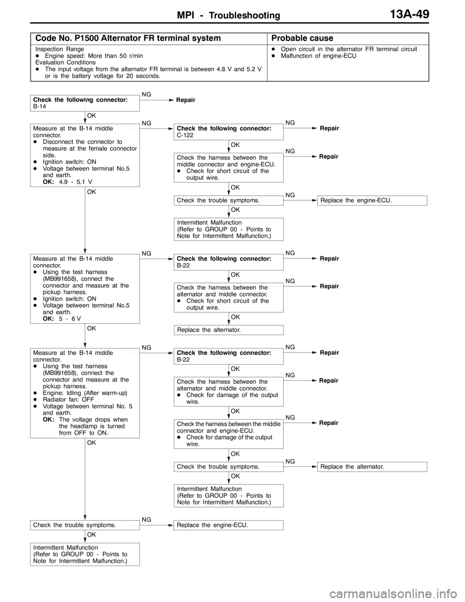
MPI -Troubleshooting13A-49
Code No. P1500 Alternator FR terminal systemProbable cause
Inspection Range
DEngine speed: More than 50 r/min
Evaluation Conditions
DThe input voltage from the alternator FR terminal is between 4.8 V and 5.2 V
or is the battery voltage for 20 seconds.DOpen circuit in the alternator FR terminal circuit
DMalfunction of engine-ECU
OK
Intermittent Malfunction
(Refer to GROUP 00 - Points to
Note for Intermittent Malfunction.)
OK
Check the trouble symptoms.NGReplace the engine-ECU.
OK
Intermittent Malfunction
(Refer to GROUP 00 - Points to
Note for Intermittent Malfunction.)
OK
Check the trouble symptoms.NGReplace the alternator. NG
OK
Check the harness between the middle
connector and engine-ECU.
DCheck for damage of the output
wire.Repair NG
OK
Check the harness between the
alternator and middle connector.
DCheck for damage of the output
wire.Repair
OK
Measure at the B-14 middle
connector.
DUsing the test harness
(MB991658), connect the
connector and measure at the
pickup harness.
DEngine: Idling (After warm-up)
DRadiator fan: OFF
DVoltage between terminal No. 5
and earth.
OK:The voltage drops when
the headlamp is turned
from OFF to ON.NGCheck the following connector:
B-22NG
Repair
OK
Replace the alternator.NG
OK
Check the harness between the
alternator and middle connector.
DCheck for short circuit of the
output wire.Repair
OK
Measure at the B-14 middle
connector.
DUsing the test harness
(MB991658), connect the
connector and measure at the
pickup harness.
DIgnition switch: ON
DVoltage between terminal No.5
and earth.
OK:5-6VNGCheck the following connector:
B-22NG
Repair
OK
Intermittent Malfunction
(Refer to GROUP 00 - Points to
Note for Intermittent Malfunction.)
OK
Check the trouble symptoms.NGReplace the engine-ECU. NG
OK
Check the harness between the
middle connector and engine-ECU.
DCheck for short circuit of the
output wire.Repair
OK
Measure at the B-14 middle
connector.
DDisconnect the connector to
measure at the female connector
side.
DIgnition switch: ON
DVoltage between terminal No.5
and earth.
OK:4.9 - 5.1 VNGCheck the following connector:
C-122NG
Repair
Check the following connector:
B-14NG
Repair
Page 596 of 1449

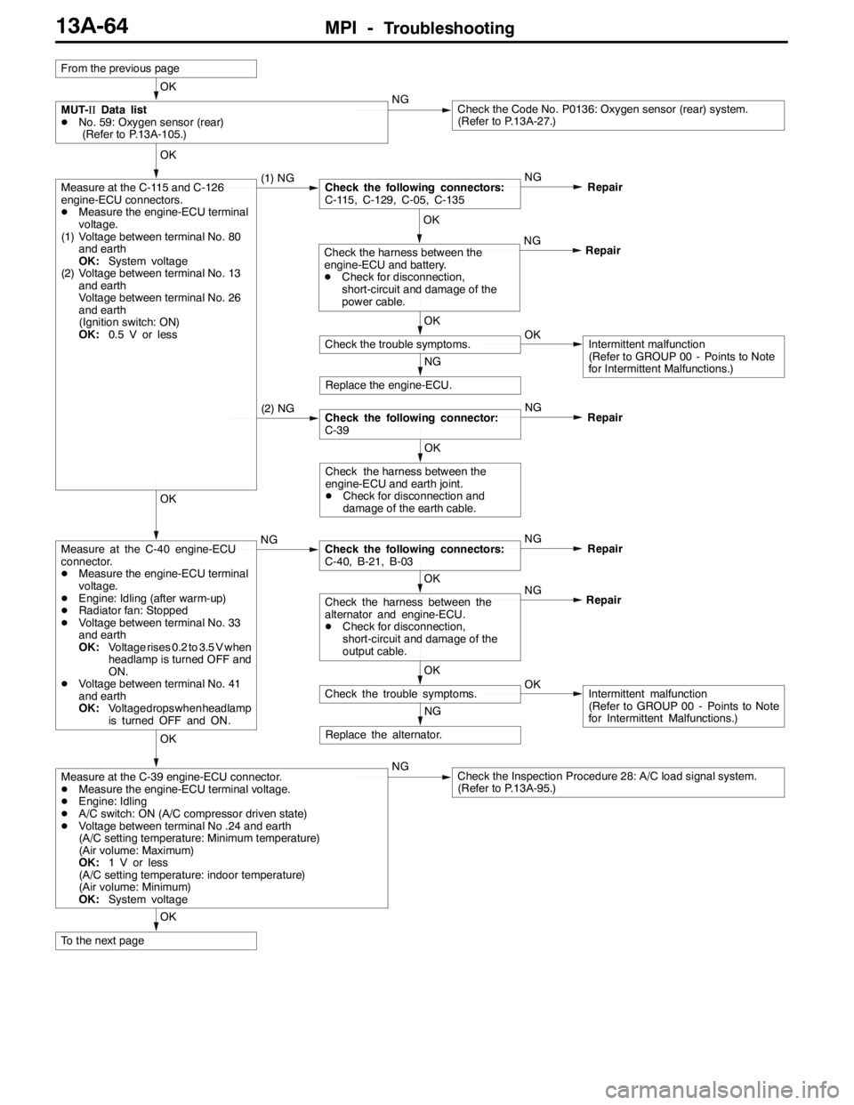
MPI -Troubleshooting13A-64
OK
To the next page
OK
Measure at the C-39 engine-ECU connector.
DMeasure the engine-ECU terminal voltage.
DEngine: Idling
DA/C switch: ON (A/C compressor driven state)
DVoltage between terminal No .24 and earth
(A/C setting temperature: Minimum temperature)
(Air volume: Maximum)
OK:1 V or less
(A/C setting temperature: indoor temperature)
(Air volume: Minimum)
OK:System voltageNGCheck the Inspection Procedure 28: A/C load signal system.
(Refer to P.13A-95.)
NG
Replace the alternator.
OK
Check the trouble symptoms.OKIntermittent malfunction
(Refer to GROUP 00 - Points to Note
for Intermittent Malfunctions.) NG
OK
Check the harness between the
alternator and engine-ECU.
DCheck for disconnection,
short-circuit and damage of the
output cable.Repair
OK
Measure at the C-40 engine-ECU
connector.
DMeasure the engine-ECU terminal
voltage.
DEngine: Idling (after warm-up)
DRadiator fan: Stopped
DVoltage between terminal No. 33
and earth
OK:Voltage rises 0.2 to 3.5 V when
headlamp is turned OFF and
ON.
DVoltage between terminal No. 41
and earth
OK:Voltage drops whenheadlamp
is turned OFF and ON.NGCheck the following connectors:
C-40, B-21, B-03NG
Repair
OK
Check the harness between the
engine-ECU and earth joint.
DCheck for disconnection and
damage of the earth cable.
(2) NGCheck the following connector:
C-39NG
Repair
NG
Replace the engine-ECU.
OK
Check the trouble symptoms.OKIntermittent malfunction
(Refer to GROUP 00 - Points to Note
for Intermittent Malfunctions.) NG
OK
Check the harness between the
engine-ECU and battery.
DCheck for disconnection,
short-circuit and damage of the
power cable.Repair
OK
Measure at the C-115 and C-126
engine-ECU connectors.
DMeasure the engine-ECU terminal
voltage.
(1) Voltage between terminal No. 80
and earth
OK:System voltage
(2) Voltage between terminal No. 13
and earth
Voltage between terminal No. 26
and earth
(Ignition switch: ON)
OK:0.5 V or less(1) NGCheck the following connectors:
C-115, C-129, C-05, C-135NG
Repair
OK
MUT-IIData list
DNo. 59: Oxygen sensor (rear)
(Refer to P.13A-105.)NGCheck the Code No. P0136: Oxygen sensor (rear) system.
(Refer to P.13A-27.)
From the previous page