headlamp MITSUBISHI LANCER EVOLUTION 2007 Service Service Manual
[x] Cancel search | Manufacturer: MITSUBISHI, Model Year: 2007, Model line: LANCER EVOLUTION, Model: MITSUBISHI LANCER EVOLUTION 2007Pages: 1449, PDF Size: 56.82 MB
Page 1347 of 1449
CHASSIS ELECTRICAL -Headlamp AssemblyCHASSIS ELECTRICAL -Headlamp Assembly54A-27
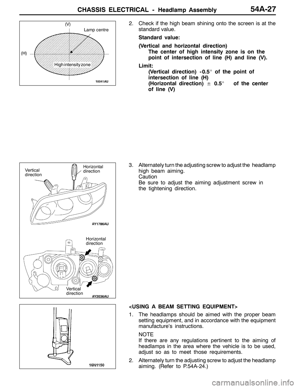
2. Check if the high beam shining onto the screen is at the
standard value.
Standard value:
(Vertical and horizontal direction)
The center of high intensity zone is on the
point of intersection of line (H) and line (V).
Limit:
(Vertical direction) - 0.5_of the point of
intersection of line (H)
(Horizontal direction)±0.5_of the center
of line (V)
3. Alternately turn the adjusting screw to adjust the headlamp
high beam aiming.
Caution
Be sure to adjust the aiming adjustment screw in
the tightening direction.
1. The headlamps should be aimed with the proper beam
setting equipment, and in accordance with the equipment
manufacture’s instructions.
NOTE
If there are any regulations pertinent to the aiming of
headlamps in the area where the vehicle is to be used,
adjust so as to meet those requirements.
2. Alternately turn the adjusting screw to adjust the headlamp
aiming. (Refer to P.54A-24.)
Lamp centre
High intensity zone (H)(V)
Vertical
direction
Vertical
direction
Horizontal
direction
Horizontal
direction
Page 1348 of 1449
CHASSIS ELECTRICAL -Headlamp Assembly54A-28
HEADLAMP INTENSITY MEASUREMENT
1. Using a photometer, and following its manufacture’s
instruction manual.
2. Maintain an engine speed of 2,000 r/min., with the battery
in the charging condition
3. Set the headlamps to high beam
4. Measure the headlamp centre intensity (a point of H line
and V line) and check to be sure that the limit value
is satisfied.
Limit:
High beam 30,000 cd or more per one headlamp
NOTE
1. There may be special local regulations pertaining to
headlamp intensity, be sure to make any adjustments
necessary to satisfy such regulations.
2. If an illuminometer is used to make the measurements,
convert its values to photometer values by using the
following formula.
I=Er
2Where:
I=intensity (cd)
E=illumination (lux)
r=distance (m) from headlamps to illuminometer
Caution
1. On the headlamp not yet adjusted, perform aiming
with connector removed and the lamps switched off,
if applicable. In addition, care should be taken to
prevent a change of optical axis when connector is
reconnected.
2. Plastic outer lens are equipped with headlamps. When
lens surface is covered with materials for not
penetrating light, headlamp operation time should be
within 3 minutes. In addition, masking such as taping
should not be performed.
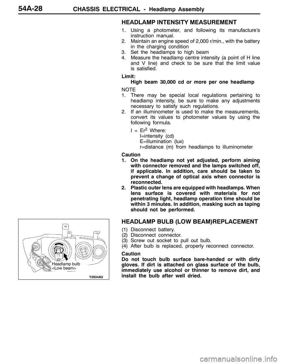
HEADLAMP BULB (LOW BEAM)REPLACEMENT
(1) Disconnect battery.
(2) Disconnect connector.
(3) Screw out socket to pull out bulb.
(4) After bulb is replaced, properly reconnect connector.
Caution
Do not touch bulb surface bare-handed or with dirty
gloves. If dirt is attached on glass surface of the bulb,
immediately use alcohol or thinner to remove dirt, and
install the bulb after well dried.
Headlamp bulb
Page 1349 of 1449
CHASSIS ELECTRICAL -Headlamp AssemblyCHASSIS ELECTRICAL -Headlamp AssemblyCHASSIS ELECTRICAL -Headlamp Assembly54A-29
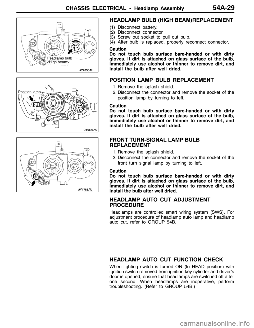
HEADLAMP BULB (HIGH BEAM)REPLACEMENT
(1) Disconnect battery.
(2) Disconnect connector.
(3) Screw out socket to pull out bulb.
(4) After bulb is replaced, properly reconnect connector.
Caution
Do not touch bulb surface bare-handed or with dirty
gloves. If dirt is attached on glass surface of the bulb,
immediately use alcohol or thinner to remove dirt, and
install the bulb after well dried.
POSITION LAMP BULB REPLACEMENT
1. Remove the splash shield.
2. Disconnect the connector and remove the socket of the
position lamp by turning to left.
Caution
Do not touch bulb surface bare-handed or with dirty
gloves. If dirt is attached on glass surface of the bulb,
immediately use alcohol or thinner to remove dirt, and
install the bulb after well dried.
FRONT TURN-SIGNAL LAMP BULB
REPLACEMENT
1. Remove the splash shield.
2. Disconnect the connector and remove the socket of the
front turn signal lamp by turning to left.
Caution
Do not touch bulb surface bare-handed or with dirty
gloves. If dirt is attached on glass surface of the bulb,
immediately use alcohol or thinner to remove dirt, and
install the bulb after well dried.
HEADLAMP AUTO CUT ADJUSTMENT
PROCEDURE
Headlamps are controlled smart wiring system (SWS). For
adjustment procedure of headlamp auto lamp and headlamp
auto cut, refer to GROUP 54B.
HEADLAMP AUTO CUT FUNCTION CHECK
When lighting switch is turned ON (to HEAD position) with
ignition switch removed from ignition key cylinder and driver’s
door is opened, ensure that headlamps are switched off after
one second. When headlamps are inoperative, perform
troubleshooting. (Refer to GROUP 54B.)
Headlamp bulb
Position lamp
Page 1350 of 1449
CHASSIS ELECTRICAL -Headlamp AssemblyCHASSIS ELECTRICAL -Headlamp Assembly54A-30
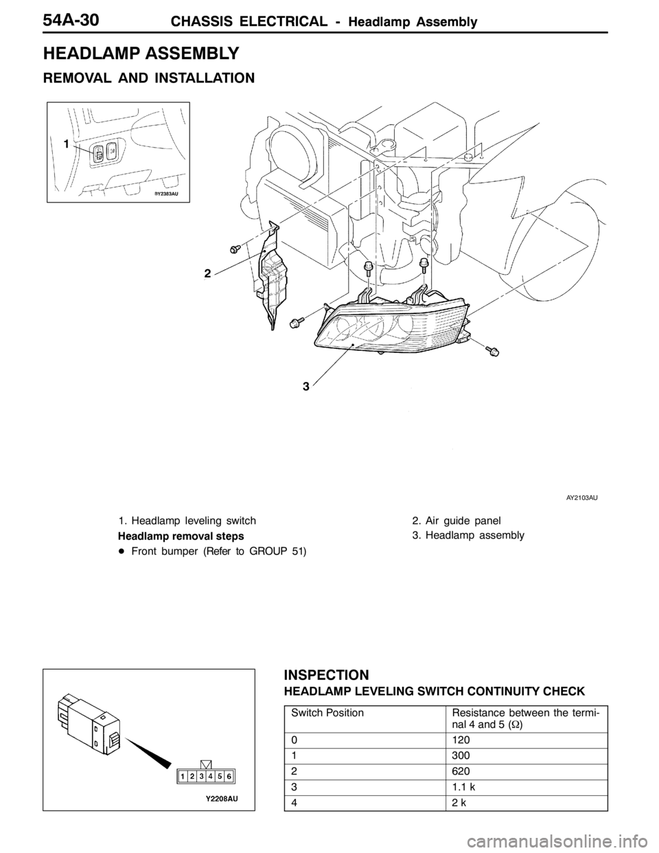
HEADLAMP ASSEMBLY
REMOVAL AND INSTALLATION
2
3
1
AY2103AU
1. Headlamp leveling switch
Headlamp removal steps
DFront bumper (Refer to GROUP 51)2. Air guide panel
3. Headlamp assembly
INSPECTION
HEADLAMP LEVELING SWITCH CONTINUITY CHECK
Switch PositionResistance between the termi-
nal 4 and 5 (Ω)
0120
1300
2620
31.1 k
42k
Page 1359 of 1449
CHASSIS ELECTRICAL-Column Switch54A-39
INSPECTION
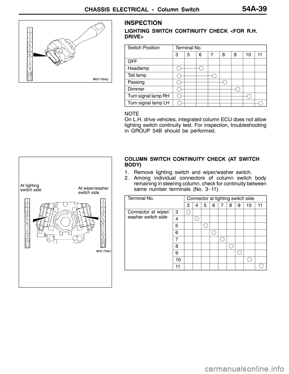
LIGHTING SWITCH CONTINUITY CHECK
Switch PositionTerminal No.
3567891011
OFF
Headlamp
Tail lamp
Passing
Dimmer
Turn signal lamp RH
Turn signal lamp LH
NOTE
On L.H. drive vehicles, integrated column ECU does not allow
lighting switch continuity test. For inspection, troubleshooting
in GROUP 54B should be performed.
COLUMN SWITCH CONTINUITY CHECK (AT SWITCH
BODY)
1. Remove lighting switch and wiper/washer switch.
2. Among individual connectors of column switch body
remaining in steering column, check for continuity between
same number terminals (No. 3 - 11).
Terminal No.Connector at lighting switch side
34567891011
Connector at wiper/
hit hid
3p
washer switch side4
5
6
7
8
9
10
11
At lighting
switch sideAt wiper/washer
switch side
Page 1367 of 1449

SWS -Troubleshooting54B-3
INPUT SIGNAL CHECK
1. Check the inputs using MUT-II or a voltmeter. (Refer to GROUP 00 - How to Use
Troubleshooting/Inspection Service Points.)
2. The following input signals can be checked using MUT-II or a voltmeter connected to the diagnosis
connector.
NOTE
When fault is detected during input signal inspection, refer to Trouble Symptom Chart to perform
troubleshooting. (Refer to P.54B-7).
Input Signal Check Function
Input signalBuzzer operation condition
Ignition switch (ACC)When ignition switch turned from “LOCK” (OFF)
to ACC.
Ignition switch (IG1)When ignition switch turned from “ACC” to “ON”.
Hazard warning lamp switchWhen switch turned from OFF to ON.
Rear fog lamp switch
Driver’s door switchWhen driver’s door opened from closed
All door switchesWhen any door opened when all doors were
closed.
Driver’s door lock actuatorWhen the driver’s side key cylinder or inside lock
knob is moved from the locked to unlocked
position or vice versa.
Vehicle speed signalVehicle speed changes from less than 10 km/h to
10 km/h or more.
Column switchesTail lamp switchWhen lighting switch turned from automatic
lighting to tail lamp position.
Headlamp switchWhen lighting switch turned from tail lamp to
headlamp position.
Dimmer switchWhen switch turned from OFF to ON.
Passing switch
Left-hand turn signal lamp switch
Right-hand turn signal lamp switch
Windshield mist wiper switch
Windshield wiper intermittent timing switch
Windshield wiper LO speed switch
Windshield wiper HI speed switch
Windshield washer switchWhen switch turned from OFF to ON.
Power window
main switchAll switchesWhen switch turned from OFF to ON.
DIAGNOSIS CODE CHART
Code No.Diagnosis itemReference page
11ETACS-ECU-related failure54B-4
12Column switch-related failure or fault in connecting to ETACS-ECU54B-4
13Front-ECU-related failure or fault in connecting to ETACS-ECU54B-5
21Short circuit in communication lines54B-6
Page 1371 of 1449

SWS -Troubleshooting54B-7
TROUBLE SYMPTOM CHART
Trouble symptomInspection
procedureReference
page
No communication with MUT-IIA-154B-10
BuzzersLights left ON reminder warning function not working normally.B-154B-10
Central lockingCentral door locking system not working at all.C-154B-11g
Some doors not locking or unlocking.C-254B-11
Power windowPower windows not working at all.D-154B-12
Power windows are not operated with the power window main
switch.
Driver’s power window not responding to power window main
switch.D-254B-13
Windows not responding to passenger or rear power window
switches.D-354B-14
Passenger or rear power windows not responding to power window
main switch.D-454B-15
Power window timer function not working normally.D-554B-15
While the window is winding up, it suddenly starts coming down
again.D-654B-16
Safety mechanism (to prevent jamming of fingers, etc.) not
working.D-754B-16
Windshield wipers
dh
The windshield wipers do not work at all.E-154B-17p
and washerThe windshield wipers only operate at LO speed (though the wipers
and washer can be switched OFF).E-254B-17
The windshield wipers do not respond to any switch position.E-354B-18
The windshield wipers do not stop in the normal predetermined
position.E-454B-18
The windshield washer does not work at all.E-554B-19
Windshield wipers are not operated with the switch in INT,
WASHER and MIST positions, and operated in a low mode with the
switch in Lo and Hi positions.E-654B-19
Headlamps, tail lampsExcept for lighting switch“OFF,” the headlamps only respond to the
“low-beam” position.
F-154B-20
The tail lamps do not work.F-254B-20
The headlamps (low-beam) do not light.F-354B-21
The headlamps (high-beam) do not light.F-454B-21
The headlamps (low or high-beam) do not work when the passing
switch is ON.F-554B-22
The headlamp automatic cut-off function is not working normally.F-654B-22
Rear fog lampRear fog lamp is not properly illuminated.G-154B-23
Flasher timerThe turn signal lamps do not light.H-154B-24
The hazard warning lamps do not light up.H-254B-24
Room lampsThe room lamps do not come ON or OFF normally.I-154B-25
Page 1372 of 1449

SWS -TroubleshootingSWS -Troubleshooting54B-8
DEFECTS FOUND BY INPUT SIGNAL CHECK
When a fault is identified in an input signal check, use the following table to investigate the fault.
Trouble symptomInspection
procedureReference
page
No ignition switch (ACC) signal input to ETACS-ECU.J-154B-26
No ignition switch (IG1) signal input to ETACS-ECU.J-254B-26
No hazard warning lamp switch signal input to ETACS-ECU.J-354B-27
No rear fog lamp switch signal input to ETACS-ECU.J-454B-28
No driver’s door switch signal input to ETACS-ECU.J-554B-29
No door switch signals input to ETACS-ECU.
No driver’s door lock actuator signal input to ETACS-ECU.J-654B-30
Column switchesNo tail lamp switch signal input to ETACS-ECU.J-754B-31
No headlamp switch signal input to ETACS-ECU.
No dimmer switch signal input to ETACS-ECU.
No passing switch signal input to ETACS-ECU.
No turn signal lamp left-hand switch signal input to
ETACS-ECU.
No turn signal lamp right-hand switch signal input to
ETACS-ECU.
Column switchesNo windshield mist wiper switch signal input to ETACS-ECU.J-854B-31
No windshield wiper intermittent switch signal input to
ETACS-ECU.
No windshield low-speed wiper switch signal input to
ETACS-ECU.
No windshield high-speed wiper switch signal input to
ETACS-ECU.
No windshield washer switch signal input to ETACS-ECU.
Power window main switchNo power window main switch signal input to ETACS-ECU.J-954B-32
When the ignition switch is in the LOCK (OFF) position, no functions work normally.K-154B-33
ETACS-ECU battery power supply circuit control check.
NOTE
A diagnosis code is output for front-ECU and column switch battery power supply circuit control abnormalities.
Apply the diagnosis code inspection procedures to address these abnormalities.
Page 1373 of 1449

SWS -Troubleshooting54B-9
Input Signal Inspection Procedure Nos. by Function
When more than one SWS function fails at the same time, run checks based on the following table.
(The table lists only input signals and functions in which multiple faults can occur.)
FunctionJ-1J-2J-3J-5J-6J-7J-8
Driver’s doorAll doors
Central locking
controlF
Power window controlF
Power window timerFF
Windshield wiper
and washer controlFF
Rear wiper and
washer controlFF
Headlamp controlF
Rear fog lamp controlF
Tail lamp controlF
Headlamp automatic
turn-offFFF
Turn signal lamp
controlFF
Hazard warning lamp
controlF
Room lamp controlFFF
Page 1374 of 1449
SWS -Troubleshooting54B-10
INSPECTION PROCEDURE FOR TROUBLE SYMPTOMS
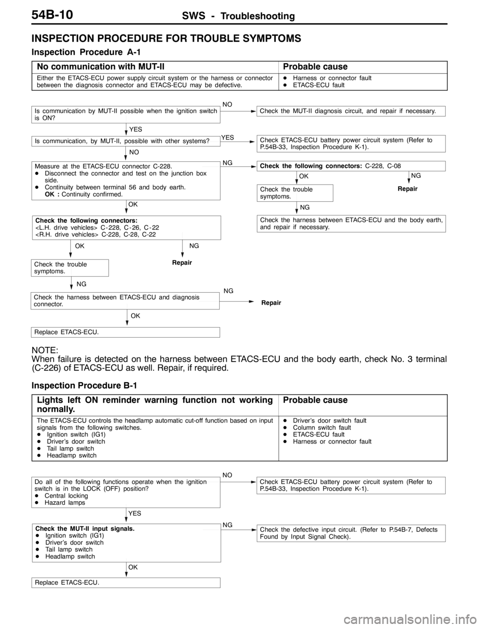
Inspection Procedure A-1
No communication with MUT-II
Probable cause
Either the ETACS-ECU power supply circuit system or the harness or connector
between the diagnosis connector and ETACS-ECU may be defective.DHarness or connector fault
DETACS-ECU fault
NG
Check the harness between ETACS-ECU and the body earth,
and repair if necessary.
NG
Repair
NG
Repair
OK
Replace ETACS-ECU.
NG
Check the harness between ETACS-ECU and diagnosis
connector.NG
Repair
OK
Check the trouble
symptoms.
OK
Check the following connectors:
OK
Check the trouble
symptoms.
NO
Measure at the ETACS-ECU connector C-228.
DDisconnect the connector and test on the junction box
side.
DContinuity between terminal 56 and body earth.
OK :Continuity confirmed.NGCheck the following connectors:C-228, C-08
YES
Is communication, by MUT-II, possible with other systems?YESCheck ETACS-ECU battery power circuit system (Refer to
P.54B-33, Inspection Procedure K-1).
Is communication by MUT-II possible when the ignition switch
is ON?NOCheck the MUT-II diagnosis circuit, and repair if necessary.
NOTE:
When failure is detected on the harness between ETACS-ECU and the body earth, check No. 3 terminal
(C-226) of ETACS-ECU as well. Repair, if required.
Inspection Procedure B-1
Lights left ON reminder warning function not working
normally.
Probable cause
The ETACS-ECU controls the headlamp automatic cut-off function based on input
signals from the following switches.
DIgnition switch (IG1)
DDriver’s door switch
DTail lamp switch
DHeadlamp switchDDriver’s door switch fault
DColumn switch fault
DETACS-ECU fault
DHarness or connector fault
OK
Replace ETACS-ECU.
YES
Check the MUT-II input signals.
DIgnition switch (IG1)
DDriver’s door switch
DTail lamp switch
DHeadlamp switchNGCheck the defective input circuit. (Refer to P.54B-7, Defects
Found by Input Signal Check).
Do all of the following functions operate when the ignition
switch is in the LOCK (OFF) position?
DCentral locking
DHazard lampsNOCheck ETACS-ECU battery power circuit system (Refer to
P.54B-33, Inspection Procedure K-1).