headlamp MITSUBISHI LANCER EVOLUTION 2007 Service Owner's Guide
[x] Cancel search | Manufacturer: MITSUBISHI, Model Year: 2007, Model line: LANCER EVOLUTION, Model: MITSUBISHI LANCER EVOLUTION 2007Pages: 1449, PDF Size: 56.82 MB
Page 610 of 1449

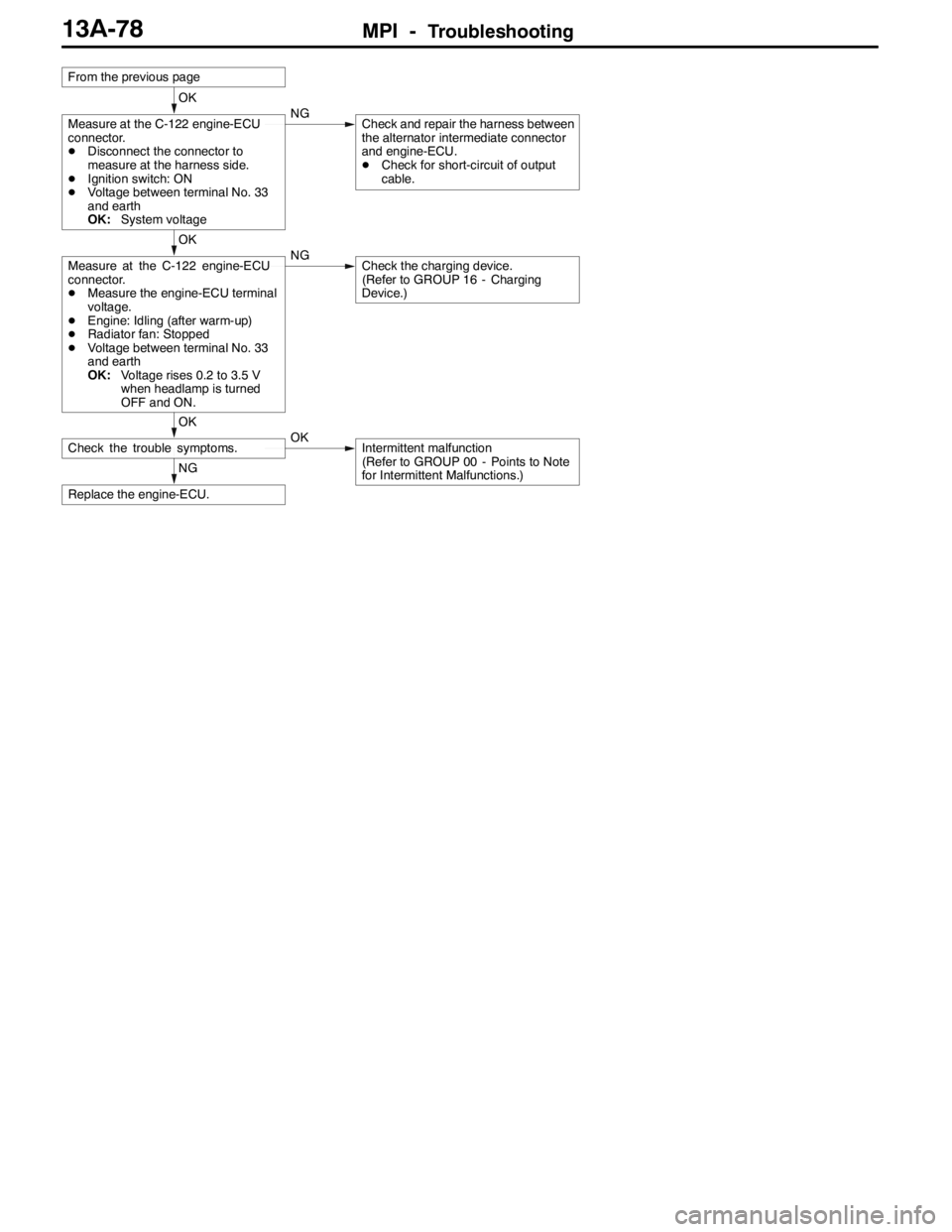
MPI -Troubleshooting13A-78
NG
Replace the engine-ECU.
OK
Check the trouble symptoms.OKIntermittent malfunction
(Refer to GROUP 00 - Points to Note
for Intermittent Malfunctions.)
OK
Measure at the C-122 engine-ECU
connector.
DMeasure the engine-ECU terminal
voltage.
DEngine: Idling (after warm-up)
DRadiator fan: Stopped
DVoltage between terminal No. 33
and earth
OK:Voltage rises 0.2 to 3.5 V
when headlamp is turned
OFF and ON.NGCheck the charging device.
(Refer to GROUP 16 - Charging
Device.)
OK
Measure at the C-122 engine-ECU
connector.
DDisconnect the connector to
measure at the harness side.
DIgnition switch: ON
DVoltage between terminal No. 33
and earth
OK:System voltageNGCheck and repair the harness between
the alternator intermediate connector
and engine-ECU.
DCheck for short-circuit of output
cable.
From the previous page
Page 642 of 1449

MPI -Troubleshooting13A-110
Terminal No.Normal condition Check condition (Engine condition) Check item
12Power supplyIgnition switch: “ON”System voltage
25
19Air flow sensor reset
signal
Engine: Idle operation0-1V
signal
Engine speed: 3,000 r/min6-9V
21Fan controllerRadiator fan is not operating0 - 0.3 V
Radiator fan is operating0.7 V or more
22Fuel pump relay 2Ignition switch: “ON”System voltage
Engine: Idle operation1 V or less
24A/C load signalDEngine:
Idle operation
DA/C switch: ON
(A/C compressor
runs)DOutdoor air
sensor ambient
temperature:
18_C or more
DA/C setting
temperature:
Minimum
temperature
DA/C air volume:
Maximum1 V or less
DA/C setting
temperature:
indoor
temperature
DA/C air volume:
MinimumSystem voltage
32Condenser fan motor
relay (HI)Fan inactive state
(Engine coolant temperature: 90_C or less)System voltage
Fan high-speed rotation state
(Engine coolant temperature: 105_C or more)1 V or less
33Alternator G terminalDEngine: After warm-up, idle operation
DRadiator fan: Not operating
DHeadlamp: OFF→ON
DStop lamp: OFF→ON
DRear defogger switch: OFF→ONVoltage increases by
0.2 - 3.5 V
34Condenser fan motor
relay (LOW)Fan inactive state
(Engine coolant temperature: 90_C or less)System voltage
Fan low-speed rotation state (Engine coolant
temperature: 95 - 100_C or more)1 V or less
35Intercooler water
spraylamp
Ignition switch: “ON”System voltage
spraylamp
Ignition switch: “LOCK” (OFF)1 V or less
36Engine warning lampIgnition switch: “LOCK” (OFF)→“ON”1 V or less→System
voltage (After several se-
conds have elapsed)
Page 737 of 1449

ENGINE ELECTRICAL -Charging System16-5
(6) Reconnect the negative battery cable.
(7) Connect a tachometer or the MUT-II.
(Refer to GROUP 11 - On-vehicle Service.)
(8) Leave the hood open.
(9) Start the engine.
(10)With the engine running at 2,500 r/min, turn
the headlamps and other lamps on and off
to adjust the alternator load so that the value
displayed on the ammeter is slightly above 30
A.
Adjust the engine speed by gradually
decreasing it until the value displayed on the
ammeter is 30 A. Take a reading of the value
displayed on the voltmeter at this time.
Limit: max. 0.3 V
NOTE
When the alternator output is high and the value
displayed on the ammeter does not decrease
until 30 A, set the value to 40 A. Read the
value displayed on the voltmeter at this time.
When the value range is 40 A, the limit is max.
0.4 V.(11) If the value displayed on the voltmeter is above
the limit value, there is probably a malfunction
in the alternator output wire, so check the wiring
between the alternator “B” terminal and the
battery (+) terminal (including fusible link).
If a terminal is not sufficiently tight or if the
harness has become discolored due to
overheating, repair and then test again.
(12)After the test, run the engine at idle.
(13)Turn off all lamps and the ignition switch.
(14)Remove the tachometer or the MUT-II.
(15)Disconnect the negative battery cable.
(16)Disconnect the ammeter and voltmeter.
(17)Connect the alternator output wire to the
alternator “B” terminal.
(18)Connect the negative battery cable.
OUTPUT CURRENT TEST
Charging warning lampVoltmeter
Ammeter
Ignition switch
Alternator relayLoad
Battery
Engine-ECUAlternatorFR
L
S
G
+ -+-
B
Page 738 of 1449

ENGINE ELECTRICAL -Charging System16-6
This test determines whether the alternator output
current is normal.
(1) Before the test, always be sure to check the
following.
DAlternator installation
DBattery (Refer to GROUP 54 - Battery.)
NOTE
The battery should be slightly discharged.
The load needed by a fully-charged battery
is insufficient for an accurate test.
DAlternator drive belt tension
(Refer to GROUP 11 - On-vehicle Service.)
DFusible link
DAbnormal noise from the alternator while
the engine is running.
(2) Turn the ignition switch to the “LOCK” (OFF)
position.
(3) Disconnect the negative battery cable.
(4) Disconnect the alternator output wire from the
alternator “B” terminal. Connect a DC test
ammeter with a range of 0 - 100 A in series
between the “B” terminal and the disconnected
output wire. (Connect the (+) lead of the
ammeter to the “B” terminal. Connect the ( - )
lead of the ammeter to the disconnected output
wire.)
Caution
Never use clips but tighten bolts and nuts
to connect the line. Otherwise loose
connections (e.g. using clips) will lead to
a serious accident because of high current.
NOTE
An inductive-type ammeter which enables
measurements to be taken without
disconnecting the alternator output wire should
be recommended.
(5) Connect a voltmeter with a range of 0 - 20 V
between the alternator “B” terminal and the
earth. (Connect the (+) lead of the voltmeter
to the “B” terminal, and then connect the ( - )
lead of the voltmeter to the earth.)
(6) Connect the negative battery cable.
(7) Connect a tachometer or the MUT-II.
(Refer to GROUP 11 - On-vehicle Service.)
(8) Leave the hood open.
(9) Check that the reading on the voltmeter is equal
to the battery voltage.
NOTE
If the voltage is 0 V, the cause is probably
an open circuit in the wire or fusible link between
the alternator “B” terminal and the battery (+)
terminal.(10)Turn the light switch on to turn on headlamps
and then start the engine.
(11) Immediately after setting the headlamps to high
beam and turning the heater blower switch to
the high revolution position, increase the engine
speed to 2,500 r/min and read the maximum
current output value displayed on the ammeter.
Limit: 70 % of normal current output
NOTE
DFor the nominal current output, refer to the
Alternator Specifications.
DBecause the current from the battery will
soon drop after the engine is started, the
above step should be carried out as quickly
as possible in order to obtain the maximum
current output value.
DThe current output value will depend on
the electrical load and the temperature of
the alternator body.
DIf the electrical load is small while testing,
the specified level of current may not be
output even though the alternator is normal.
In such cases, increase the electrical load
by leaving the headlamps turned on for
some time to discharge the battery or by
using the lighting system in another vehicle,
and then test again.
DThe specified level of current also may not
be output if the temperature of the alternator
body or the ambient temperature is too
high. In such cases, cool the alternator and
then test again.
(12)The reading on the ammeter should be above
the limit value. If the reading is below the limit
value and the alternator output wire is normal,
remove the alternator from the engine and
check the alternator.
(13)Run the engine at idle after the test.
(14)Turn the ignition switch to the “LOCK” (OFF)
position.
(15)Remove the tachometer or the MUT-II.
(16)Disconnect the negative battery cable.
(17)Disconnect the ammeter and voltmeter.
(18)Connect the alternator output wire to the
alternator “B” terminal.
(19)Connect the negative battery cable.
Page 742 of 1449

ENGINE ELECTRICAL -Charging System16-10
EXAMPLES OF ABNORMAL WAVEFORMS
NOTE
1. The size of the waveform patterns differs largely, depending on the adjustment of the variable knob
on the analyzer.
2. Identification of abnormal waveforms is easier when there is a large output current (regulator is not
operating). (Waveforms can be observed when the headlamps are illuminated.)
3. Check the conditions of the charging warning lamp (illuminated/not illuminated). Also, check the charging
system totally.
Abnormal waveformsProblem
causeAbnormal waveformsProblem
cause
Example 1Open diodeExample 4Short in
stator coil
Example 2Short in diodeExample 5Open
supplementa-
ry diode
Example 3Broken wire
in stator coil
At this time, the charging warning lamp
is illuminated.
ALTERNATOR
REMOVAL AND INSTALLATION
Caution
If the vehicle is equipped with the Brembo disc brake, during maintenance, take care not to contact
the parts or tools to the caliper because the paint of caliper will be scratched.
Pre-removal and Post-installation Operation
DUnder Cover Removal and Installation (Refer to GROUP 51 - Front Bumper.)
DDrive Belt Tension Check (Refer to GROUP 11A - On-vehicle Service.)
DStrut Tower Bar Removal and Installation (Refer to GROUP 42.)
DCrossmember Bar Removal and Installation (Refer to GROUP 32 - Engine Roll Stopper, Centermember.)
DFront Exhaust Pipe Assembly Removal and Installation (Refer to GROUP 15.)
Page 1322 of 1449

54A-2
CHASSIS
ELECTRICAL
CONTENTS
BATTERY 4..............................
SERVICE SPECIFICATION 4....................
ON-VEHICLE SERVICE 4......................
Fluid Level and Specific Gravity Check 4........
Charging 4.................................
Battery Testing Procedure 5...................
IGNITION SWITCH AND IMMOBILIZER
SYSTEM 6...............................
SPECIAL TOOLS 6............................
TROUBLESHOOTING 6........................
IMMOBILIZER-ECU CHECK 10.................
IGNITION SWITCH 11..........................
COMBINATION METER 14................
SERVICE SPECIFICATIONS 14.................
SEALANT 14..................................
SPECIAL TOOLS 15...........................
TROUBLESHOOTING 15.......................
ON-VEHICLE SERVICE 19.....................Speedometer Check 19......................
Tachometer Check 20........................
Fuel Gauge Unit Check 20....................
Engine Coolant Temperature Gauge
Unit Check 21...............................
COMBINATION METER 22.....................
HEADLAMP ASSEMBLY 24...............
SERVICE SPECIFICATIONS 24.................
TROUBLESHOOTING 24.......................
ON-VEHICLE SERVICE 24.....................
Headlamp Aiming 24.........................
Headlamp Intensity Measurement 28...........
Headlamp Bulb(low beam)Replacement28 ....
Headlamp Bulb(high beam)Replacement29 ...
Position Lamp Bulb Replacement29 ...........
Front Turn Signal Lamp Bulb Replacement29 ...
Headlamp Auto Cut Adjustment Procedure29 ...
HeadlampAuto Cut Function Check 29.........
HEADLAMP ASSEMBLY 30....................
CONTINUED ON NEXT PAGE
Page 1325 of 1449

CHASSIS ELECTRICAL -Battery54A-5
Caution
1. The battery plugs should be removed during charging.
2. The battery electrolyte level may rise and overflow from the battery during charging.
3. Explosions may occur if the battery is brought close to naked flames during charging.
4. Be careful to avoid tasks that might produce sparks or other danger while the battery is
charging.
5. After charging is complete, replace the battery plugs, pour water over the battery to rinse
away any sulphuric acid, and let the battery stand to dry.
6. Charge the battery in a well-ventilated location.
7. Do not let the battery electrolyte temperature rise above approximately 45_C
(approximately 55_Cduring rapid charging).
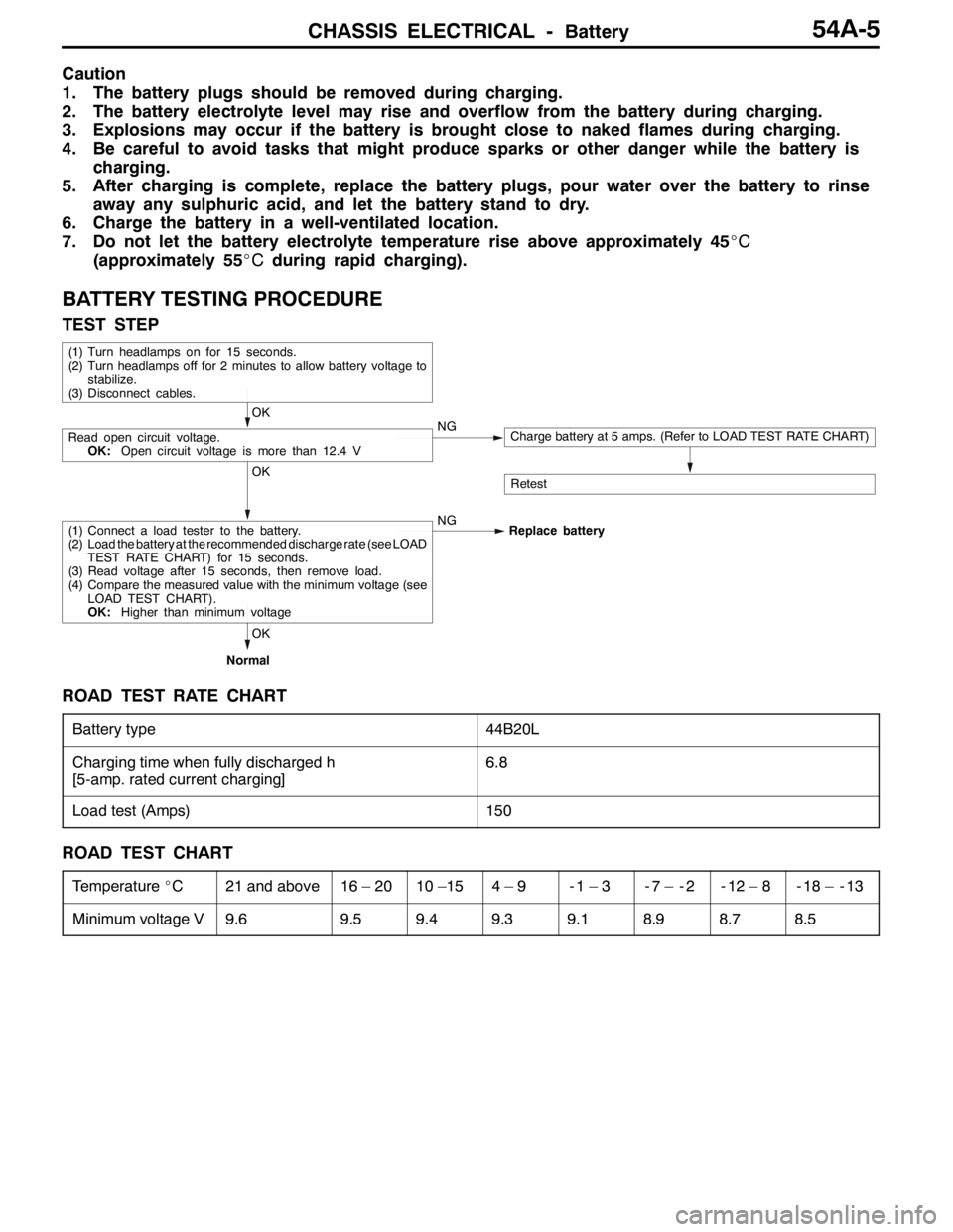
BATTERY TESTING PROCEDURE
TEST STEP
(1) Turn headlamps on for 15 seconds.
(2) Turn headlamps off for 2 minutes to allow battery voltage to
stabilize.
(3) Disconnect cables.
OK
Read open circuit voltage.
OK:Open circuit voltage is more than 12.4 VNGCharge battery at 5 amps. (Refer to LOAD TEST RATE CHART)
RetestOK
(1) Connect a load tester to the battery.
(2) Load the battery at the recommended discharge rate (see LOAD
TEST RATE CHART) for 15 seconds.
(3) Read voltage after 15 seconds, then remove load.
(4) Compare the measured value with the minimum voltage (see
LOAD TEST CHART).
OK:Higher than minimum voltageNG
Replace battery
OK
Normal
ROAD TEST RATE CHART
Battery type44B20L
Charging time when fully discharged h
[5-amp. rated current charging]6.8
Load test (Amps)150
ROAD TEST CHART
Temperature_C21 and above16 – 2010 –154–9-1–3-7 – -2-12 – 8-18 – -13
Minimum voltage V9.69.59.49.39.18.98.78.5
Page 1344 of 1449

CHASSIS ELECTRICAL -Headlamp Assembly54A-24
HEADLAMP ASSEMBLY
SERVICE SPECIFICATIONS
ItemStandard valueLimit
Headlamp aimingLow beamVertical
direction120mm (0.69_) below hor-
izontal line (H)±0.29_
Horizontal
directionPosition at which the
startup point of 15_is
crossed with vertical line
(V)±0.5_
High beamVertical
directionThe center of high intensi-
ty zone is on the point of
intersection of line (H) and
line (V).- 0.5_of the point of
intersection of line (H)
Horizontal
directionThe center of high intensi-
ty zone is on the point of
intersection of line (V).±0.5_of the center of
line (V)
Measurement of headlamp illuminous intensity
(at high beam)–30,000 cd or more per
one headlamp
NOTES ON HEADLAMP ASSEMBLY:
Plastic outer lens are equipped with headlamp assembly. For handling, care should be taken for
the following items:
DHeadlamps should not be illuminated for more than 3 minutes with scratch preventive protectors,
etc. covered on them.
DMasking such as taping should not be attached on outer lens.
DOuter lens surface should not be rubbed with a sharp-edged tool, etc.
DSpecified wax remover should be used for insistently washing.
DAuthorized Mitsubishi Genuine bulbs should be used.
TROUBLESHOOTING
Headlamps are controlled smart wiring system (SWS). For troubleshooting, refer to GROUP 54B.
NOTE
When ETACS-ECU is defective, headlamps can be illuminated only in a low beam mode as fail-safe
function.
ON-VEHICLE SERVICE
HEADLAMP AIMING
PRE-AIMING INSTRUCTION
1. Inspect for badly rusted or faulty headlamp assemblies.
2. These conditions must be corrected before a satisfactory
adjustment can be made.
3. Inspect tyres inflation, and adjust if necessary.
Page 1345 of 1449

CHASSIS ELECTRICAL -Headlamp Assembly54A-25
4. If the fuel tank is not full, place a weight in luggage room
of vehicle to simulate weight of a full tank 0.8 kg per litre.
5. There should be no other load in the vehicle other than
driver or substituted weight of approximately 75 kg placed
in driver’s position.
6. Thoroughly clean headlamp lenses.
7. Place the vehicle on a level floor, perpendicular to a flat
screen 10m away from the bulb center - marks on the
headlamp lens.
8. Rock vehicle sideways to allow vehicle to assume its
normal position.
9. Bounce the front suspension through three (3) oscillations
by applying the body weight to hood or bumper.
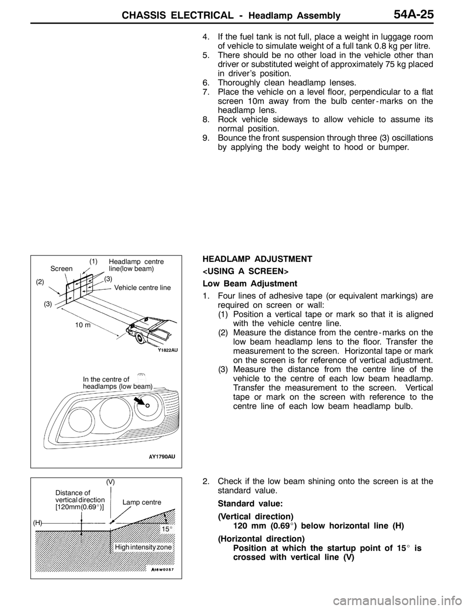
HEADLAMP ADJUSTMENT
Low Beam Adjustment
1. Four lines of adhesive tape (or equivalent markings) are
required on screen or wall:
(1) Position a vertical tape or mark so that it is aligned
with the vehicle centre line.
(2) Measure the distance from the centre - marks on the
low beam headlamp lens to the floor. Transfer the
measurement to the screen. Horizontal tape or mark
on the screen is for reference of vertical adjustment.
(3) Measure the distance from the centre line of the
vehicle to the centre of each low beam headlamp.
Transfer the measurement to the screen. Vertical
tape or mark on the screen with reference to the
centre line of each low beam headlamp bulb.
2. Check if the low beam shining onto the screen is at the
standard value.
Standard value:
(Vertical direction)
120 mm (0.69_) below horizontal line (H)
(Horizontal direction)
Position at which the startup point of 15_is
crossed with vertical line (V)
(1)
(2)(3)
Headlamp centre
line(low beam)
Vehicle centre line
Screen
10 m
In the centre of
headlamps (low beam) (3)
Distance of
vertical direction
[120mm(0.69_)]Lamp centre
15_
High intensity zone (H)(V)
Page 1346 of 1449

CHASSIS ELECTRICAL -Headlamp Assembly54A-26
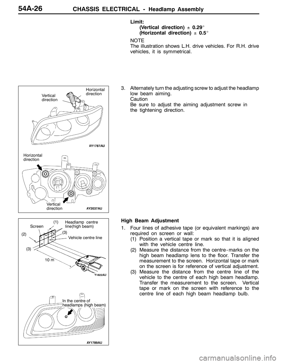
Limit:
(Vertical direction)±0.29_
(Horizontal direction)±0.5_
NOTE
The illustration shows L.H. drive vehicles. For R.H. drive
vehicles, it is symmetrical.
3. Alternately turn the adjusting screw to adjust the headlamp
low beam aiming.
Caution
Be sure to adjust the aiming adjustment screw in
the tightening direction.
High Beam Adjustment
1. Four lines of adhesive tape (or equivalent markings) are
required on screen or wall:
(1) Position a vertical tape or mark so that it is aligned
with the vehicle centre line.
(2) Measure the distance from the centre - marks on the
high beam headlamp lens to the floor. Transfer the
measurement to the screen. Horizontal tape or mark
on the screen is for reference of vertical adjustment.
(3) Measure the distance from the centre line of the
vehicle to the centre of each high beam headlamp.
Transfer the measurement to the screen. Vertical
tape or mark on the screen with reference to the
centre line of each high beam headlamp bulb.
Horizontal
direction
Vertical
direction
Horizontal
direction
Vertical
direction
(1)
(2)(3)Vehicle centre line
Screen
10 m
In the centre of
headlamps (high beam)
Headlamp centre
line(high beam)
(3)