brake sensor MITSUBISHI LANCER EVOLUTION 2007 Service Repair Manual
[x] Cancel search | Manufacturer: MITSUBISHI, Model Year: 2007, Model line: LANCER EVOLUTION, Model: MITSUBISHI LANCER EVOLUTION 2007Pages: 1449, PDF Size: 56.82 MB
Page 108 of 1449
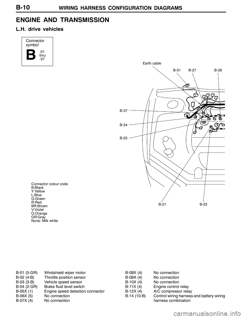
WIRING HARNESS CONFIGURATION DIAGRAMS
Connector
symbol
-01
thru
-37
B
B-37
B-34
B-23
B-01B-27B-26
Earth cable
B-21B-22
Connector colour code
B:Black
Y:Yellow
L:Blue
G:Green
R:Red
BR:Brown
V:Violet
O:Orange
GR:Gray
None: Milk white
B-10
ENGINE AND TRANSMISSION
L.H. drive vehicles
B-01 (5-GR) Windshield wiper motor
B-02 (4-B) Throttle position sensor
B-03 (3-B) Vehicle speed sensor
B-04 (2-GR) Brake fluid level switch
B-05X (1) Engine speed detection connector
B-06X (5) No connection
B-07X (4) No connectionB-08X (4) No connection
B-09X (4) No connection
B-10X (4) No connection
B-11X (4) Engine control relay
B-12X (4) A/C compressor relay
B-14 (10-B) Control wiring harness and battery wiring
harness combination
Page 112 of 1449
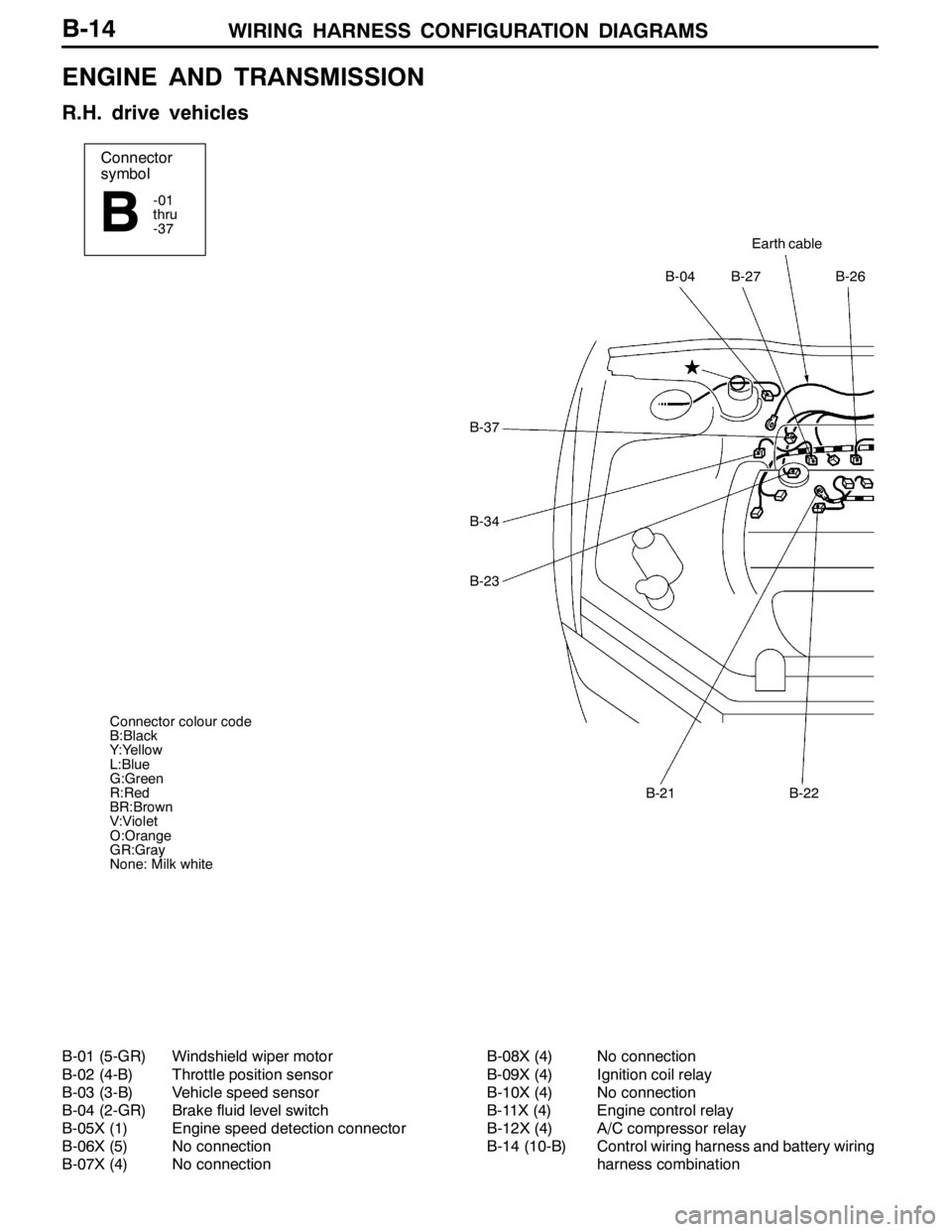
WIRING HARNESS CONFIGURATION DIAGRAMS
Connector
symbol
-01
thru
-37
B
Earth cable
B-27B-26B-04
B-22B-21
B-37
B-34
B-23
Connector colour code
B:Black
Y:Yellow
L:Blue
G:Green
R:Red
BR:Brown
V:Violet
O:Orange
GR:Gray
None: Milk white
B-14
ENGINE AND TRANSMISSION
R.H. drive vehicles
B-01 (5-GR) Windshield wiper motor
B-02 (4-B) Throttle position sensor
B-03 (3-B) Vehicle speed sensor
B-04 (2-GR) Brake fluid level switch
B-05X (1) Engine speed detection connector
B-06X (5) No connection
B-07X (4) No connectionB-08X (4) No connection
B-09X (4) Ignition coil relay
B-10X (4) No connection
B-11X (4) Engine control relay
B-12X (4) A/C compressor relay
B-14 (10-B) Control wiring harness and battery wiring
harness combination
Page 129 of 1449
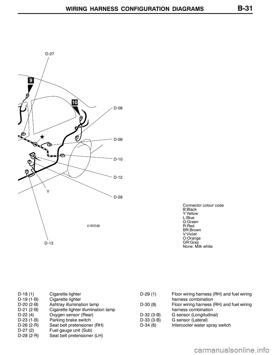
WIRING HARNESS CONFIGURATION DIAGRAMS
D-13
D-27
D-08
D-09
D-10
D-12
D-28 Y
9
10
Connector colour code
B:Black
Y:Yellow
L:Blue
G:Green
R:Red
BR:Brown
V:Violet
O:Orange
GR:Gray
None: Milk white
B-31
D-18 (1) Cigarette lighter
D-19 (1-B) Cigarette lighter
D-20 (2-B) Ashtray illumination lamp
D-21 (2-B) Cigarette lighter illumination lamp
D-22 (4) Oxygen sensor (Rear)
D-23 (1-B) Parking brake switch
D-26 (2-R) Seat belt pretensioner (RH)
D-27 (2) Fuel gauge unit (Sub)
D-28 (2-R) Seat belt pretensioner (LH)D-29 (1) Floor wiring harness (RH) and fuel wiring
harness combination
D-30 (8) Floor wiring harness (RH) and fuel wiring
harness combination
D-32 (3-B) G sensor (Longitudinal)
D-33 (3-B) G sensor (Lateral)
D-34 (6) Intercooler water spray switch
Page 131 of 1449
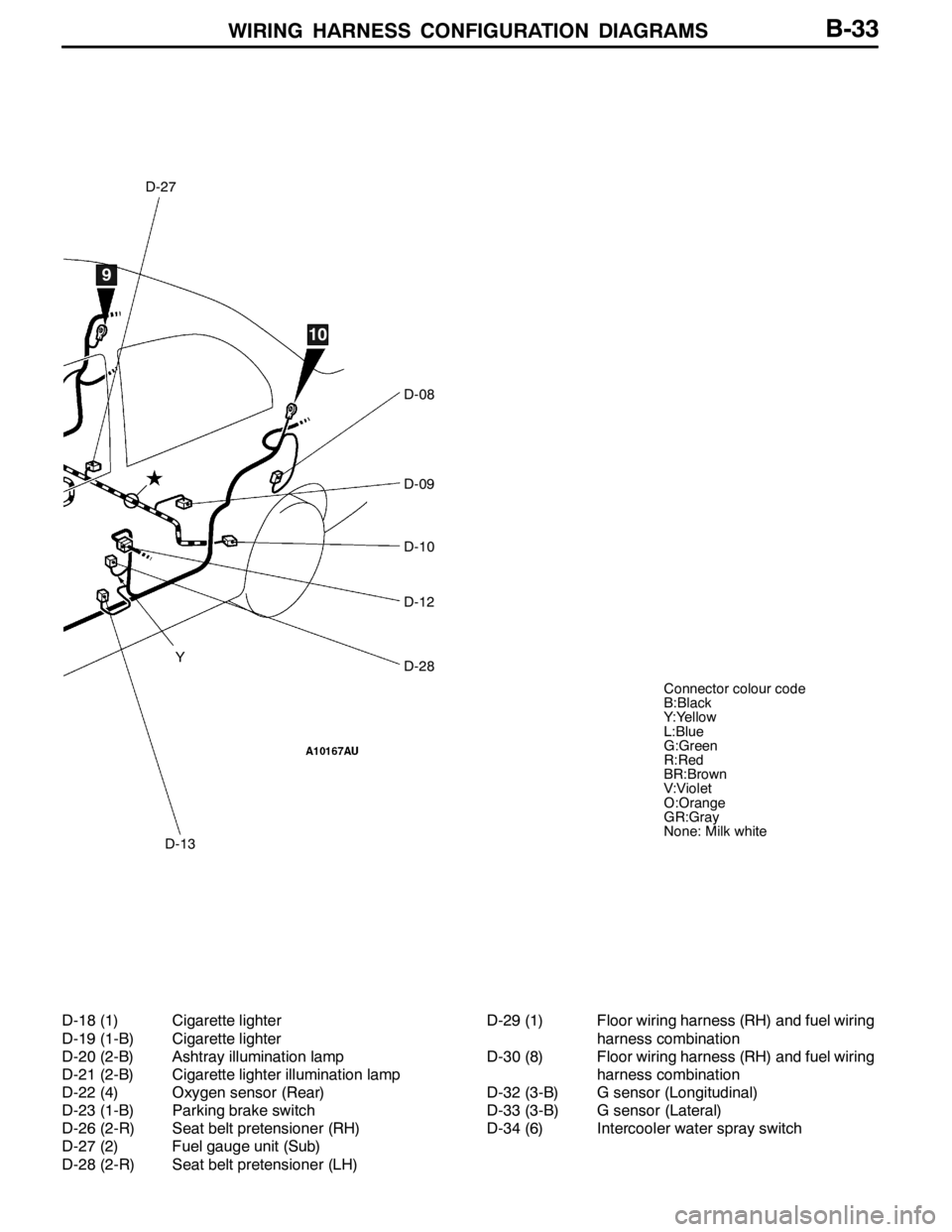
WIRING HARNESS CONFIGURATION DIAGRAMS
D-27
D-13
D-08
D-09
D-10
D-12
D-28
9
10
Y
Connector colour code
B:Black
Y:Yellow
L:Blue
G:Green
R:Red
BR:Brown
V:Violet
O:Orange
GR:Gray
None: Milk white
B-33
D-18 (1) Cigarette lighter
D-19 (1-B) Cigarette lighter
D-20 (2-B) Ashtray illumination lamp
D-21 (2-B) Cigarette lighter illumination lamp
D-22 (4) Oxygen sensor (Rear)
D-23 (1-B) Parking brake switch
D-26 (2-R) Seat belt pretensioner (RH)
D-27 (2) Fuel gauge unit (Sub)
D-28 (2-R) Seat belt pretensioner (LH)D-29 (1) Floor wiring harness (RH) and fuel wiring
harness combination
D-30 (8) Floor wiring harness (RH) and fuel wiring
harness combination
D-32 (3-B) G sensor (Longitudinal)
D-33 (3-B) G sensor (Lateral)
D-34 (6) Intercooler water spray switch
Page 143 of 1449
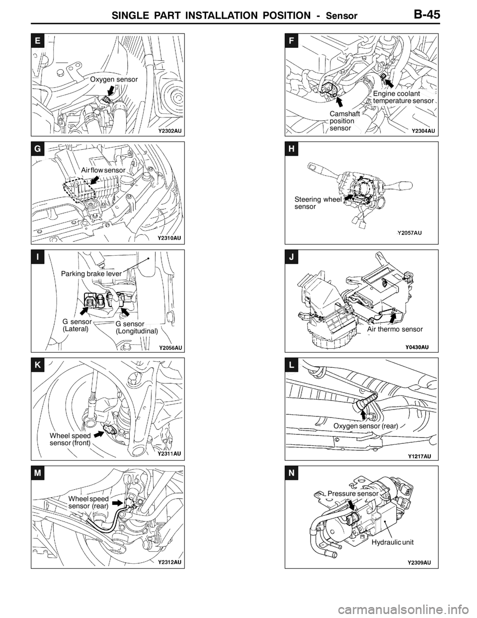
SINGLE PART INSTALLATION POSITION -Sensor
E
Oxygen sensor
F
Camshaft
position
sensor
Engine coolant
temperature sensor
G
Air flow sensor
H
Steering wheel
sensor
I
G sensor
(Lateral)
Parking brake lever
G sensor
(Longitudinal)
J
Air thermo sensor
K
Wheel speed
sensor (front)
L
Oxygen sensor (rear)
M
Wheel speed
sensor (rear)
N
Pressure sensor
Hydraulic unit
B-45
Page 358 of 1449

INDEX - In order of connector No.C-2
Wiring diagram
page Circuit diagram page Parts name Connector
No.
AA-45Condenser fan motorB-177,183B-7,9
A-46Condenser fan motorB-177,183B-7,9
A-47A/C compressorB-178,184B-7,9
A-48Power steering oil pressure switchB-90,98B-7,9
BB-01Windshield wiper motorB-186,190B-10,14
B-02Throttle position sensorB-89,97,215,223,231,241B-10,14
B-03Vehicle speed sensorB-92,100,150,154,197B-10,14
B-04Brake fluid level switchB-157B-10,14
B-05XEngine speed detection connectorB-73,82,83,90,98B-10,14
B-06XNo connectionB-73B-10,14
B-07XNo connectionB-73B-10,14
B-08XNo connectionB-73B-10,14
B-09XIgnition coil relay
connection
B-10XNo connectionB-73B-10,14
B-11XEngine control relayB-73,86,94,252,254B-10,14
B-12XA/C compressor relayB-73,178,184B-10,14
B-14Control wiring harness and battery
wiring harness combinationB-79,84,91,99,157B-10,14
B-18StarterB-79B-11,15
B-19StarterB-79B-11,15
B-20Oil pressure switchB-157B-11,15
B-21AlternatorB-84B-11,15
B-22AlternatorB-84B-11,15
B-23Purge control solenoid valveB-91,99B-11,15
B-24Injector 4B-89,97B-11,15
B-25Injector 3B-89,97B-11,15
B-26Injector 2B-89,97B-11,15
B-27Injector 1B-89,97B-11,15
B-31Air flow sensorB-90,98B-11,15
B-34Oxygen sensorB-88,96B-11,15
B-36Waste gate solenoid valveB-91,99B-11,15
B-37Fuel pressure solenoid valveB-90,98B-11,15
Page 364 of 1449

INDEX - In order of connector No.C-8
Wiring diagram
page Circuit diagram page Parts name Connector
No.
CC-223Fuel pump relay 1B-54,55,87,95B-23,29
C-224Power window relayB-54,55,158,159,165B-23,29
C-225No connectionB-54,55,78B-23,29
C-226ETACS-ECUB-54,55,105,108,112,113,116,117,118,
119,120,121,122,123,125,126,128,
129,134,136,137,138,140,141,158,
164,165, 170,171,172,173,188,189B-23,29
C-227ETACS-ECUB-125,128,170,172B-23,29
C-228ETACS-ECUB-105,108,112,113,116,117,118,119,
122,123,125,126,128,129,136,137,
140,141,158,159,164,165,170,171,
172,173, 188,189,258B-23,29
C-230Steering wheel sensorB-202,210,218,226,236,246B-23,29
DD-01Door switch (Front:RH)B-108,116,120,121,164B-30,32
D-02Floor wiring harness (RH) and rear door
wiring harness (RH) combinationB-160,166,171,173B-30,32
D-03Room lampB-118,122B-30,32
D-04Wheel speed sensor (Rear:RH)
D-05Rear room lampB-118,122B-30,32
D-06Door switch (Rear:RH)B-120,121B-30,32
D-08Door switch (Rear:LH)B-120,121B-30,32
D-09Fuel pump and fuel gauge unit (Main)B-93,101,148,152,156B-30,32
D-10Wheel speed sensor (Rear:LH)
D-12Floor wiring harness (LH) and rear door
wiring harness (LH) combinationB-161,167,171,173B-30,32
D-13Door switch (Front:LH)B-105,112,120,121,158B-30,32
D-15Instrument panel wiring harness and
console wiring harness combinationB-195B-31,32
D-18Cigarette lighterB-195B-31,33
D-19Cigarette lighterB-195B-31,33
D-20Ashtray illumination lampB-195B-31,33
D-21Cigarette lighter illumination lampB-195B-31,33
D-22Oxygen sensor (Rear)B-88,96B-31,33
D-23Parking brake switchB-157,201,209,213,221,232,242B-31,33
D-26Seat belt pretensioner (RH)B-249,251B-31,33
Page 367 of 1449

INDEX - In order of parts nameC-11
INDEX
In order of parts name
Parts nameConnector
No.Circuit diagram pageWiring diagram
page
4WD-ECU
219,220,221,222,223,224,226,227,
228,230,231,232,234,236,237,238,
240,241,242,244, 246,247B-19,25
4WD-ECU
221,224,225,227,228,229,232,234,
235,237,238,239,242,244,245,247B-19,25
AA/C compressorA-47B-178,184B-7,9
A/C compressor relayB-12XB-73,178,184B-10,14
A/C-ECU or heater control unitC-32B-175,181,185B-19,25
ABS-ECUB-123B-198,200,201,202,203,204,205,206,
208,209,210,211,229,232,233,239,
242,243B-13,17
ACD mode changeover switchC-142B-214,222,230,240B-21,27
Air bag module (squib)
Air bag module (squib)
Air flow sensorB-31B-90,98B-11,15
AlternatorB-21B-84B-11,15
AlternatorB-22B-84B-11,15
Ashtray illumination lampD-20B-195B-31,33
BBack-up lamp switchB-108B-142,143B-12,16
Blower motorC-14B-174,180B-18,24
Blower relayC-215B-54,55,174,180B-23,29
Blower switchC-131B-174,180B-21,27
Brake fluid level switchB-04B-157B-10,14
CCamshaft position sensorB-116B-88,96B-12,16
Cigarette lighterD-18B-195B-31,33
Cigarette lighterD-19B-195B-31,33
Cigarette lighter illumination lampD-21B-195B-31,33
ClockC-04B-194B-18,24
Clock spring
Clock spring
Page 374 of 1449

INDEX - In order of parts nameC-18
Wiring diagram
page Circuit diagram page Connector
No. Parts name
KKey reminder switchC-202B-253,255B-22,28
LLicence plate lamp (LH)F-13B-110,114B-38,39
Licence plate lamp (RH)F-12B-110,114B-38,39
Luggage compartment lampF-04B-119,123B-38,39
NNo connectionA-08XB-73B-6,8
No connectionA-34-B-9
No connectionB-07XB-73B-10,14
No connectionB-08XB-73B-10,14
No connectionB-10XB-73B-10,14
No connectionC-220B-54,55B-23,29
No connectionB-06XB-73B-10,14
No connectionC-225B-54,55,78B-23,29
No connection
OOil pressure switchB-20B-157B-11,15
Outside/Inside air selection damper
control motor and potentiometerC-10B-175,181B-18,24
Oxygen sensorB-34B-88,96B-11,15
Oxygen sensor (Rear)D-22B-88,96B-31,33
PParking brake switchD-23B-157,201,209,213,221,232,242B-31,33
Power steering oil pressure switchA-48B-90,98B-7,9
Power window main switchE-07B-162,163,168,169B-34,36
Power window motor (Front:LH)E-05B-162,165B-34,36
Power window motor (Front:RH)E-20B-159,168B-35,37
Power window motor (Rear:LH)E-10B-161,167B-34,36
Power window motor (Rear:RH)E-25B-160,166B-35,37
Power window relayC-224B-54,55,158,159,165B-23,29
Power window sub switch (Passenger’s
side)E-19B-159,165B-35,37
Power window sub switch (Rear:LH)E-11B-161,167B-34,36
Power window sub switch (Rear:RH)E-24B-160,166B-35,37
Pressure sensor
Proportioning valve (for ACD control)F-27B-216,224,235,245B-38,39
Proportioning valve (for AYC control)F-28B-235,245B-38,39
Page 435 of 1449
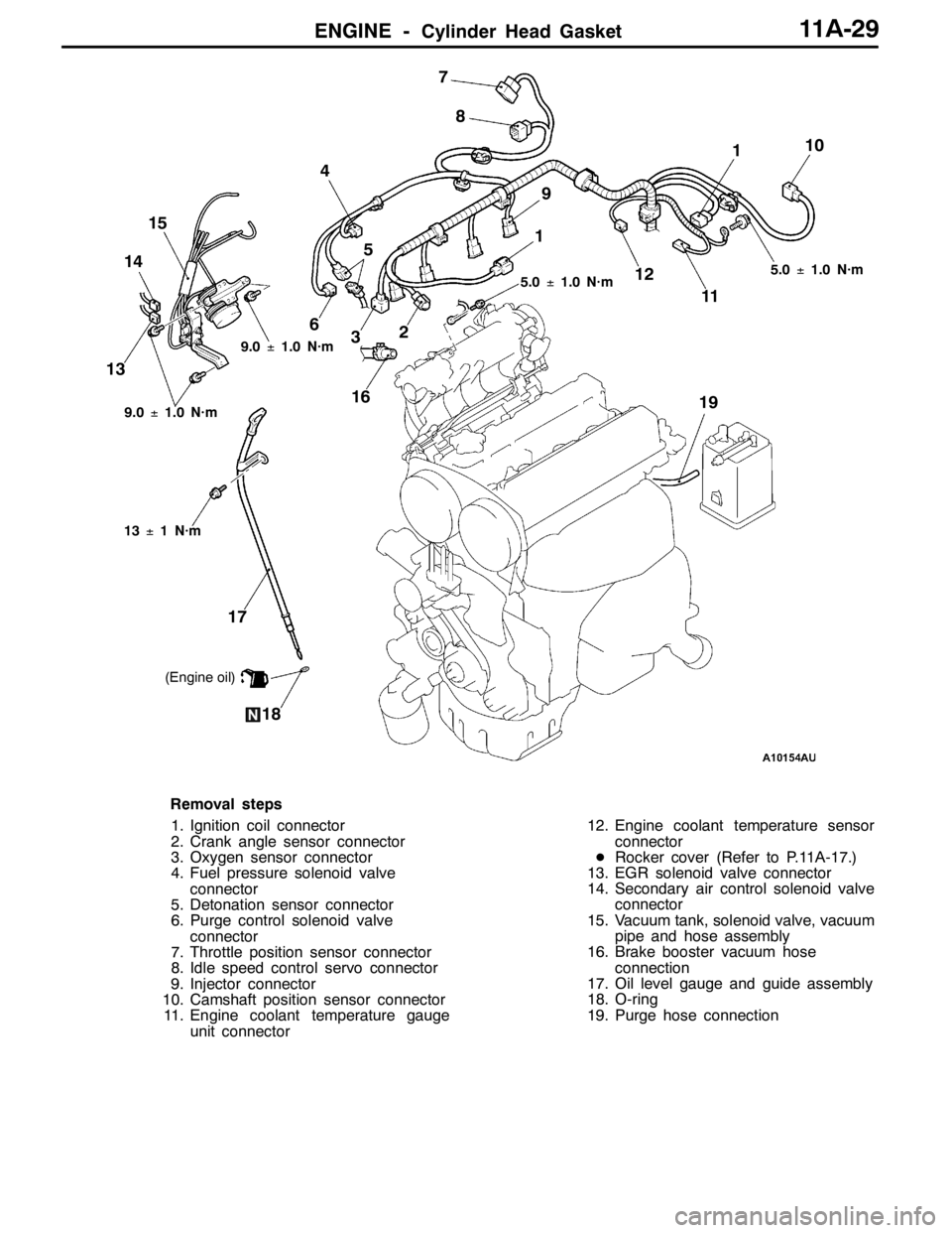
ENGINE -Cylinder Head Gasket11A-29
5.0±1.0 N·m
61
2
3 4
57
8
910
11 12
1314
13±1 N·m
15
16
17
5.0±1.0 N·m
1819
9.0±1.0 N·m
9.0±1.0 N·m
(Engine oil)
1
Removal steps
1. Ignition coil connector
2. Crank angle sensor connector
3. Oxygen sensor connector
4. Fuel pressure solenoid valve
connector
5. Detonation sensor connector
6. Purge control solenoid valve
connector
7. Throttle position sensor connector
8. Idle speed control servo connector
9. Injector connector
10. Camshaft position sensor connector
11. Engine coolant temperature gauge
unit connector12. Engine coolant temperature sensor
connector
DRocker cover (Refer to P.11A-17.)
13. EGR solenoid valve connector
14. Secondary air control solenoid valve
connector
15. Vacuum tank, solenoid valve, vacuum
pipe and hose assembly
16. Brake booster vacuum hose
connection
17. Oil level gauge and guide assembly
18. O-ring
19. Purge hose connection