MITSUBISHI LANCER EVOLUTION 2007 Service Repair Manual
Manufacturer: MITSUBISHI, Model Year: 2007, Model line: LANCER EVOLUTION, Model: MITSUBISHI LANCER EVOLUTION 2007Pages: 1449, PDF Size: 56.82 MB
Page 701 of 1449
ENGINE COOLING -Water Pump14-13
WATER PUMP
Caution
If the vehicle is equipped with the Brembo disc brake, during maintenance, take care not to contact
the parts or tools to the caliper because the paint of caliper will be scratched.
REMOVAL AND INSTALLATION
Pre-remobal and Post-installation Operation
DEngine Coolant Draining and Supplying (Refer to P.14-6.)
DTiming Belt Removal and installation (Refer to GROUP 11A.)
1
Bolt specifications
28×22
2
23±3 N·m
14±1 N·m
Nominal diameter×Nominal length mm
8×70
8×14
8×22 8×25
3 4
22±4 N·m
Removal steps
1. Alternator brace
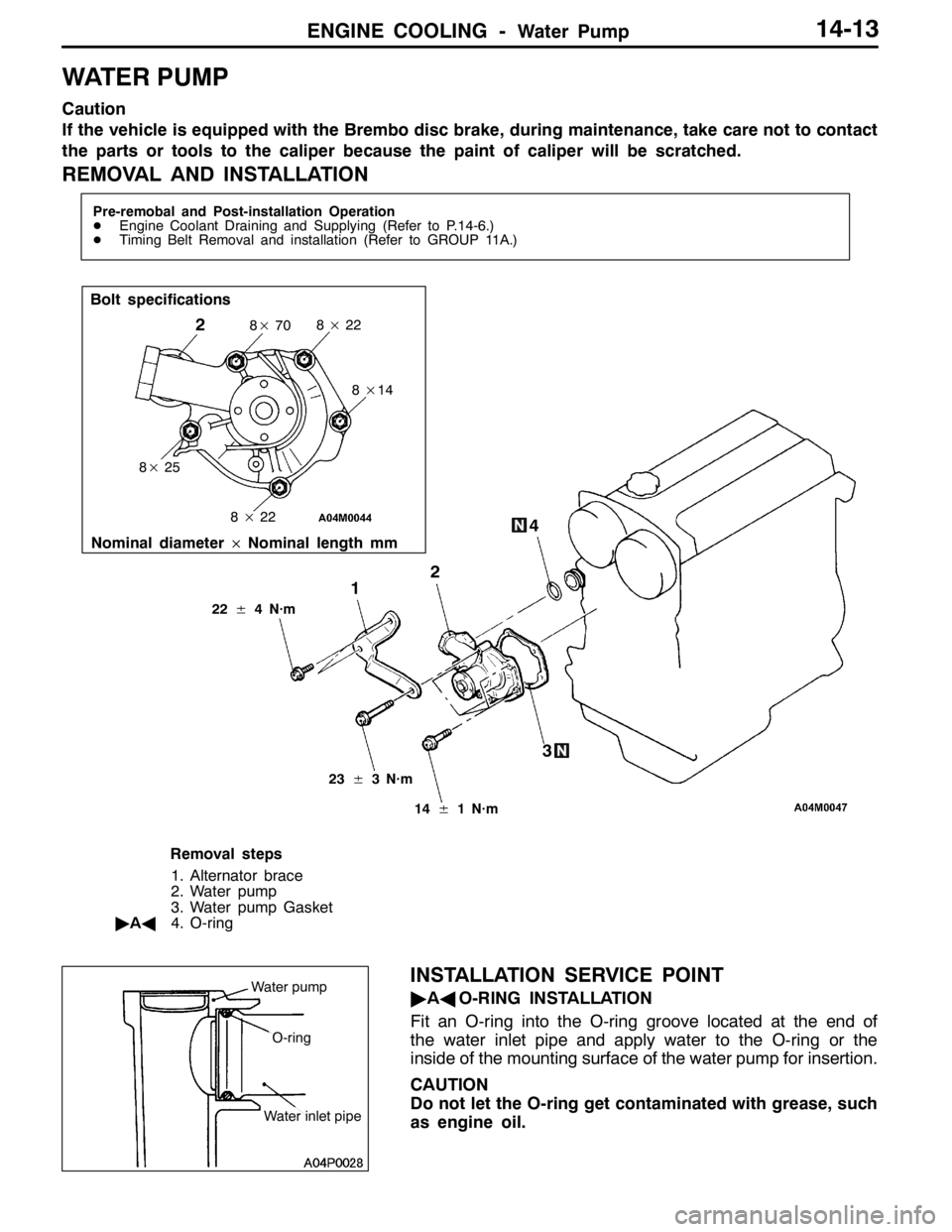
2. Water pump
3. Water pump Gasket
"AA4. O-ring
INSTALLATION SERVICE POINT
"AAO-RING INSTALLATION
Fit an O-ring into the O-ring groove located at the end of
the water inlet pipe and apply water to the O-ring or the
inside of the mounting surface of the water pump for insertion.
CAUTION
Do not let the O-ring get contaminated with grease, such
as engine oil.Water pump
O-ring
Water inlet pipe
Page 702 of 1449
ENGINE COOLING -Water Hose and Water Pipe14-14
WATER HOSE AND WATER PIPE
REMOVAL AND INSTALLATION
Pre-remobal and Post-installation Operation
DEngine Coolant Draining and Supplying (Refer to P.14-6.)
DAir Cleaner Assembly Removal and Installation (Refer to GROUP 15 - Air Cleaner.)
DAir Bypass Valve Assembly, Air Bypass Hose, Air Hose E and Air Pipe C, Air Hose D Removal and
Installation (Refer to GROUP 15 - Intercooler.)
DSecondary Air Control Valve Bracket Removal and Installation
(Refer to GROUP 15 - Secondary Air Supply System.)
DBattery, Battery Tray Removal and Installation
3 4
5 6
7 8
9
1012
10±1 N·m
42±7 N·m 13±2 N·m
11
1
2
23±4 N·m
18
1716 1514
13
19
10±1 N·m
42±7 N·m
10±1 N·m
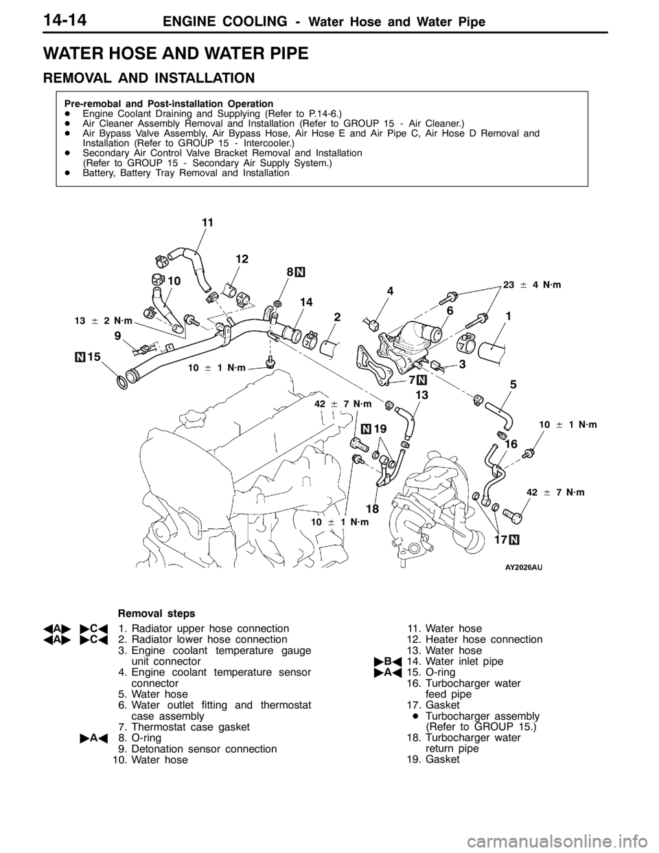
Removal steps
AA""CA1. Radiator upper hose connection
AA""CA2. Radiator lower hose connection
3. Engine coolant temperature gauge
unit connector
4. Engine coolant temperature sensor
connector
5. Water hose
6. Water outlet fitting and thermostat
case assembly
7. Thermostat case gasket
"AA8. O-ring
9. Detonation sensor connection
10. Water hose11. Water hose
12. Heater hose connection
13. Water hose
"BA14. Water inlet pipe
"AA15. O-ring
16. Turbocharger water
feed pipe
17. Gasket
DTurbocharger assembly
(Refer to GROUP 15.)
18. Turbocharger water
return pipe
19. Gasket
Page 703 of 1449
ENGINE COOLING -Water Hose and Water Pipe/Radiator14-15
REMOVAL SERVICE POINT
AA"RADIATOR UPPER HOSE/RADIATOR LOWER
HOSE DISCONNECTION
After making mating marks on the hose and the hose clamp,
disconnect the hose.
INSTALLATION SERVICE POINTS
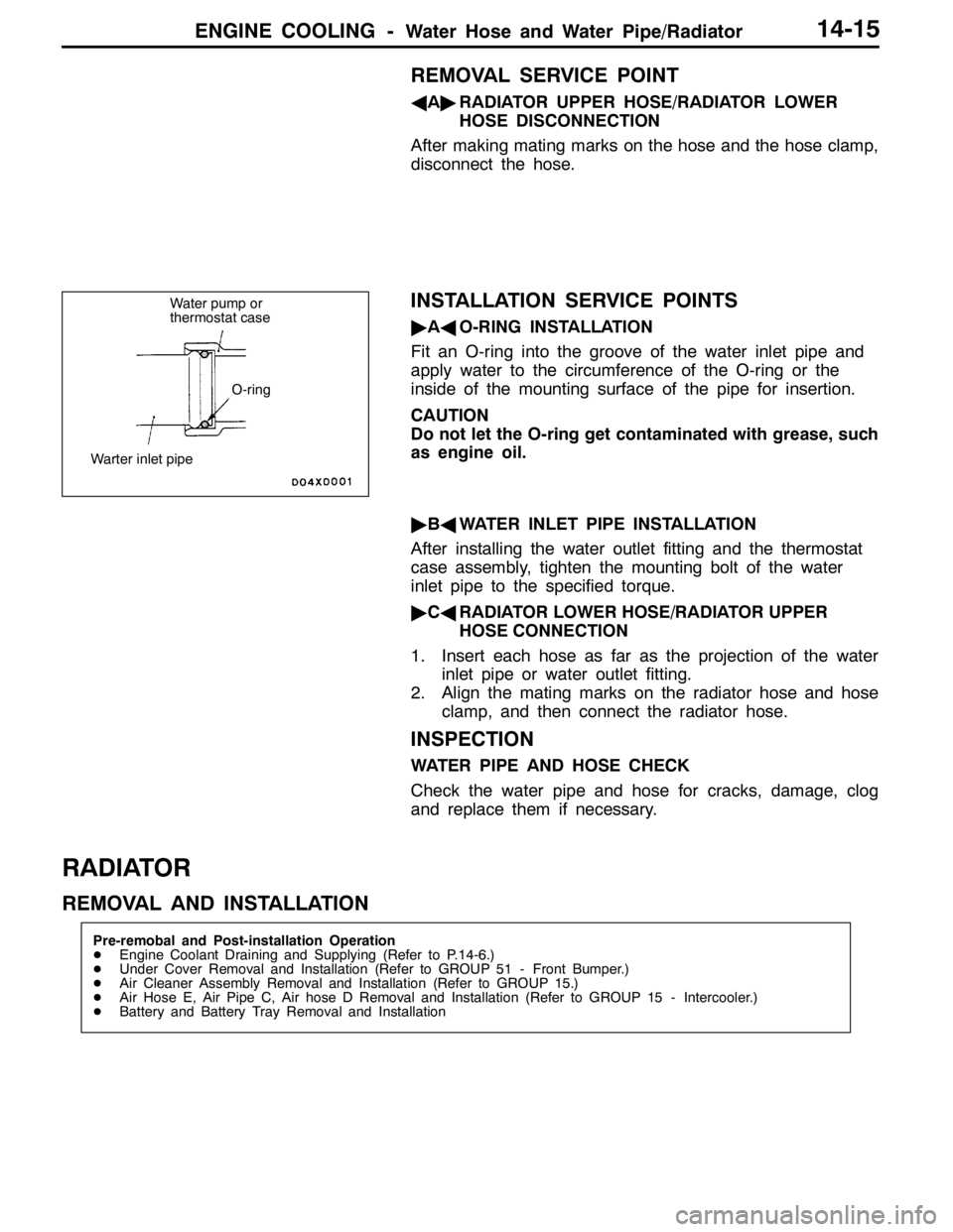
"AAO-RING INSTALLATION
Fit an O-ring into the groove of the water inlet pipe and
apply water to the circumference of the O-ring or the
inside of the mounting surface of the pipe for insertion.
CAUTION
Do not let the O-ring get contaminated with grease, such
as engine oil.
"BAWATER INLET PIPE INSTALLATION
After installing the water outlet fitting and the thermostat
case assembly, tighten the mounting bolt of the water
inlet pipe to the specified torque.
"CARADIATOR LOWER HOSE/RADIATOR UPPER
HOSE CONNECTION
1. Insert each hose as far as the projection of the water
inlet pipe or water outlet fitting.
2. Align the mating marks on the radiator hose and hose
clamp, and then connect the radiator hose.
INSPECTION
WATER PIPE AND HOSE CHECK
Check the water pipe and hose for cracks, damage, clog
and replace them if necessary.
RADIATOR
REMOVAL AND INSTALLATION
Pre-remobal and Post-installation Operation
DEngine Coolant Draining and Supplying (Refer to P.14-6.)
DUnder Cover Removal and Installation (Refer to GROUP 51 - Front Bumper.)
DAir Cleaner Assembly Removal and Installation (Refer to GROUP 15.)
DAir Hose E, Air Pipe C, Air hose D Removal and Installation (Refer to GROUP 15 - Intercooler.)
DBattery and Battery Tray Removal and Installation
Water pump or
thermostat case
O-ring
Warter inlet pipe
Page 704 of 1449

ENGINE COOLING -Radiator14-16
1 23
45
6
7
12±2 N·m
9
16
14 19
18 12
17 10
8
13
15 10
20 21
12±2 N·m5.0±1.0 N·m
3.5±0.4 N·m
4.5±0.4 N·m4.0±0.4 N·m
13
1112±1 N·m
Radiator removal steps
1. Radiator drain plug
2. Radiator cap
3. Reserve tank hose
4. Reserve tank
5. Reserve tank cap
6. Reserve tank hose
7. Reserve tank bracket
AA""AA8. Radiator upper hose
AA""AA9. Radiator lower hose
10. Upper insulator
AB"11. Air Pipe B mounting bolt
12. Radiator assembly
13. Lower insulator
14. Radiator fan controller connector
15. Radiator fan controller, radiator fan
motor, fan and shroud assemblyRadiator fun controller and radiator
fun motor removal steps
AB"11. Air Pipe B mounting bolt
14. Radiator fan controller connector
16. Radiator fan motor connector
17. Radiator fan controller
18. Radiator fan motor fan and shroud
assembly
19. Fan
20. Radiator fan motor
21. Shroud
Page 705 of 1449

ENGINE COOLING -RadiatorENGINE COOLING -Radiator14-17
REMOVAL SERVICE POINTS
AA"RADIATOR UPPER HOSE/RADIATOR LOWER
HOSE REMOVAL
After making mating marks on the radiator hose and the hose
clamp,disconnect the radiator hose.
AB"AIR PIPE B MOUNTING BOLT REMOVAL
After removing the bolt, position air pipe B out of the way
so that the pipe does not interfere with the radiator assembly
or the radiator fan motor, the fan and shroud assembly.
INSTALLATION SERVICE POINT
"AARADIATOR LOWER HOSE/RADIATOR UPPER
HOSE INSTALLATION
1. Insert each hose as far as the projection of the water
inlet pipe, water outlet fitting or radiator.
2. Align the mating marks on the radiator upper hose and
hose clamp, and then connect the radiator hose.
Page 706 of 1449

NOTES
Page 707 of 1449

15-1
INTAKE AND
EXHAUST
CONTENTS
GENERAL INFORMATION 2..................
SERVICE SPECIFICATION 3..................
SPECIAL TOOL 3............................
ON-VEHICLE SERVICE 3.....................
Turbocharger Supercharging Pressure Check 3...
Supercharging Pressure Control System
Check 4.......................................
Waste Gate Actuator Check 4...................
Waste Gate Solenoid Valve Check 5.............
Air Bypass Valve Check 5......................
Intake Manifold Pressure Check 6...............
Secondary Air Control System Check 6..........
Secondary Air Control Solenoid Valve Check 6...
Secondary Air Valve Check 7...................Vacuum Tank Check 7.........................
AIR CLEANER 8.............................
INTERCOOLER 9............................
INTERCOOLER WATER SPRAY 10............
SECONDARY AIR SUPPLY SYSTEM 14.......
INTAKE MANIFOLD 16.......................
EXHAUST MANIFOLD 19.....................
TURBOCHARGER 22.........................
EXHAUST PIPE AND MAIN MUFFLER 26.....
CATALYTIC CONVERTER
(REFER TO GROUP 17.) ....................
Page 708 of 1449
INTAKE AND EXHAUST -General Information15-2
GENERAL INFORMATION
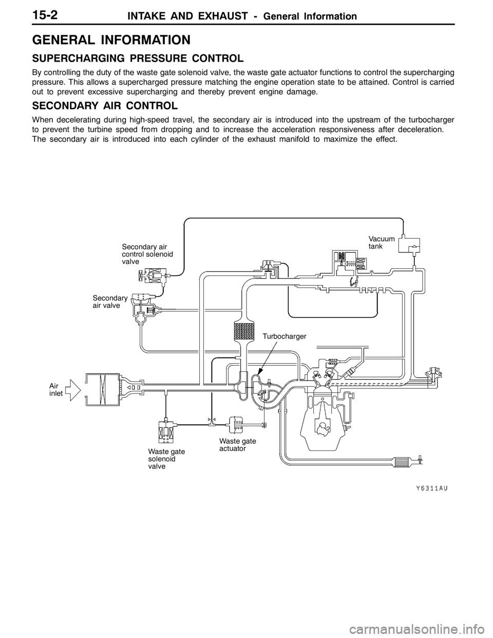
SUPERCHARGING PRESSURE CONTROL
By controlling the duty of the waste gate solenoid valve, the waste gate actuator functions to control the supercharging
pressure. This allows a supercharged pressure matching the engine operation state to be attained. Control is carried
out to prevent excessive supercharging and thereby prevent engine damage.
SECONDARY AIR CONTROL
When decelerating during high-speed travel, the secondary air is introduced into the upstream of the turbocharger
to prevent the turbine speed from dropping and to increase the acceleration responsiveness after deceleration.
The secondary air is introduced into each cylinder of the exhaust manifold to maximize the effect.
Secondary air
control solenoid
valve
Air
inletSecondary
air valve
Waste gate
solenoid
valve
Waste gate
actuator
TurbochargerVacuum
tank
Page 709 of 1449
INTAKE AND EXHAUST -Service Specifications/Special Tool/On-vehicle Service15-3
SERVICE SPECIFICATIONS
ItemStandard valueLimit
Turbocharger supercharging pressure (waste gate solenoid
valve not operating) kPa59 - 84-
Initial activation pressure of waste gate actuator (at the stroke
of approximately 1 mm) kPaApproximately 100-
Waste gate solenoid valve coil resistance (at 20_C)Ω29 - 35-
Initial activation pressure of air bypass valve kPaApproximately 53-
Secondary air control solenoid valve coil resistance
(at 20_C)Ω29 - 35-
Manifold distortion of the installation surface mm0.15 or less0.20
SPECIAL TOOL
ToolNumberNameUse
MD998770Oxygen sensor wrenchRemoval and installation of oxygen sensor
ON-VEHICLE SERVICE
TURBOCHARGER SUPERCHARGING
PRESSURE CHECK
Caution
Two persons should be in the vehicle when the test is
conducted; the person in the passenger seat should read
the indications shown by the pressure meter.
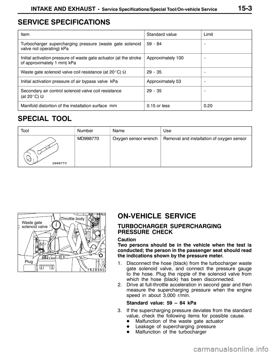
1. Disconnect the hose (black) from the turbocharger waste
gate solenoid valve, and connect the pressure gauge
to the hose. Plug the nipple of the solenoid valve from
which the hose (black) has been disconnected.
2. Drive at full-throttle acceleration in second gear and then
measure the supercharging pressure when the engine
speed in about 3,000 r/min.
Standard value: 59 – 84 kPa
3. If the supercharging pressure deviates from the standard
value, check the following items for possible cause.
DMalfunction of the waste gate actuator
DLeakage of supercharging pressure
DMalfunction of the turbocharger
Throttle bodyWaste gate
solenoid valve
Plug
Page 710 of 1449
INTAKE AND EXHAUST -On-vehicle Service15-4
4. When the indicated supercharging is more than standard
value, supercharging control may be faulty, therefore
check the followings.
DMalfunction of the waste gate actuator
DMalfunction of waste gate valve
DDisconnection or cracks of the waste gate actuator
rubber hose
SUPERCHARGING PRESSURE CONTROL
SYSTEM CHECK
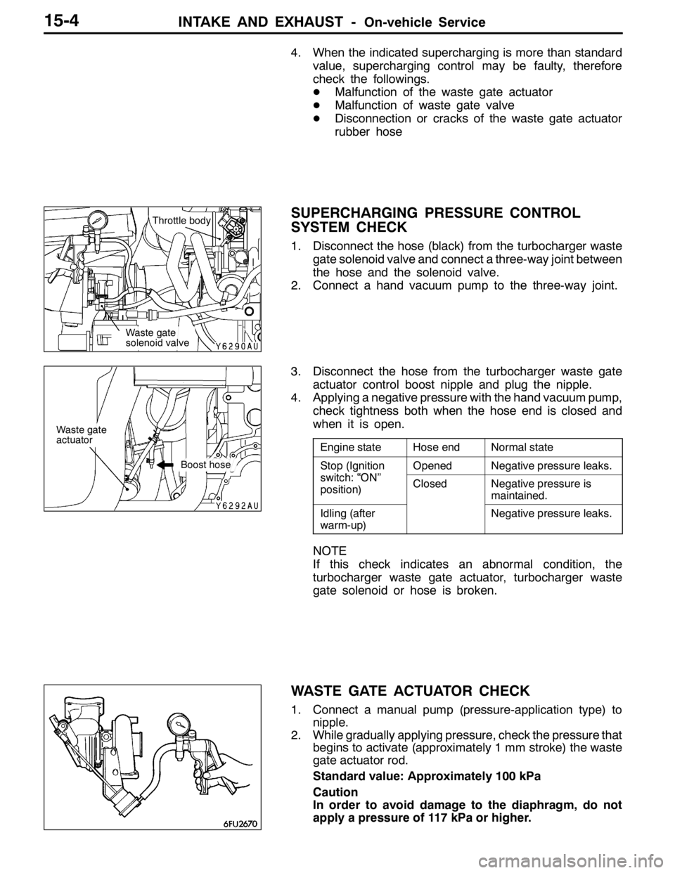
1. Disconnect the hose (black) from the turbocharger waste
gate solenoid valve and connect a three-way joint between
the hose and the solenoid valve.
2. Connect a hand vacuum pump to the three-way joint.
3. Disconnect the hose from the turbocharger waste gate
actuator control boost nipple and plug the nipple.
4. Applying a negative pressure with the hand vacuum pump,
check tightness both when the hose end is closed and
when it is open.
Engine stateHose endNormal state
Stop (Ignition
it h“ON”
OpenedNegative pressure leaks.p(g
switch: “ON”
position)ClosedNegative pressure is
maintained.
Idling (after
warm-up)Negative pressure leaks.
NOTE
If this check indicates an abnormal condition, the
turbocharger waste gate actuator, turbocharger waste
gate solenoid or hose is broken.
WASTE GATE ACTUATOR CHECK
1. Connect a manual pump (pressure-application type) to
nipple.
2. While gradually applying pressure, check the pressure that
begins to activate (approximately 1 mm stroke) the waste
gate actuator rod.
Standard value: Approximately 100 kPa
Caution
In order to avoid damage to the diaphragm, do not
apply a pressure of 117 kPa or higher.
Waste gate
solenoid valveThrottle body
Waste gate
actuator
Boost hose