Functions MITSUBISHI LANCER EVOLUTION X 2008 Workshop Manual
[x] Cancel search | Manufacturer: MITSUBISHI, Model Year: 2008, Model line: LANCER EVOLUTION X, Model: MITSUBISHI LANCER EVOLUTION X 2008Pages: 241, PDF Size: 8.26 MB
Page 8 of 241
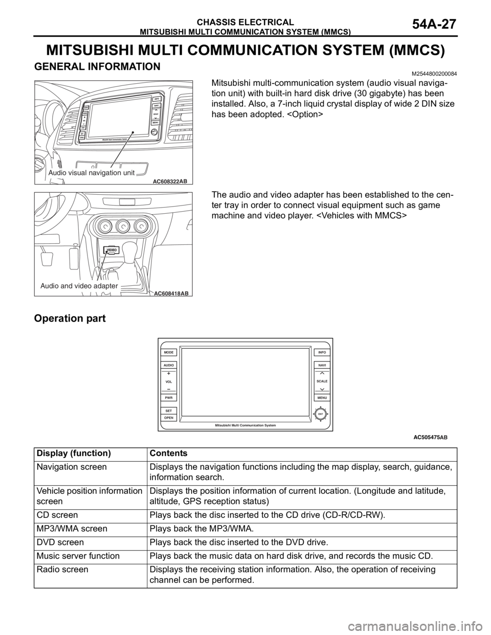
MITSUBISHI MULTI COMMUNICATION SYSTEM (MMCS)
CHASSIS ELECTRICAL54A-27
MITSUBISHI MULTI COMMUNICATION SYSTEM (MMCS)
GENERAL INFORMATIONM2544800200084
Mitsubishi multi-communication system (audio visual naviga-
tion unit) with built-in hard disk drive (30 gigabyte) has been
installed. Also, a 7-inch liquid crystal display of wide 2 DIN size
has been adopted.
Page 9 of 241
MITSUBISHI MULTI COMMUNICATION SYSTEM (MMCS)
CHASSIS ELECTRICAL54A-28
Navigation function
The storage of very large map data is now possible,
and the following contents have been adopted.
•Map type navigation
•NAVTEQ map database
•Map data stored in hard disc drive
•U.S. English, French, and Spanish are available
to select.
Audio and visual function
The following functions are in addition to the naviga-
tion function:
•Music server function
•DVD drive unit
•FM/AM radio
•MP3/WMA playback function
•Control by steering wheel audio remote comtrol
switch
•Integrated 4-ch power amplifier (MAX: 180 W)
•Correspond to Rockford Fosgate® premium
sound system
•Output of DVD video 5.1 channel data
•Connect with satellite radio tuner
Other function
The following functions are in addition to the naviga-
tion, audio and visual function:
•Clock display
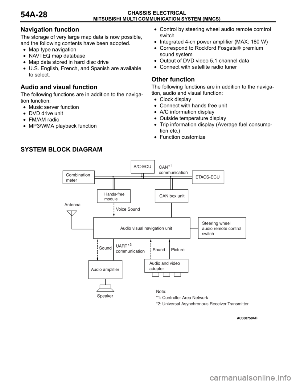
•Connect with hands free unit
•A/C information display
•Outside temperature display
•Trip information display (Average fuel consump-
tion etc.)
•Function customize
SYSTEM BLOCK DIAGRAM
AC505476
AC608750 ZC3050180000
Audio and video
adopter Antenna
Steering wheel
audio remote control
switch
Speaker
*1: Controller Area Network Note:
*2: Universal Asynchronous Receiver Transmitter UART
communicationn
Sound Sound Voice Sound
Picture
Audio amplifierCAN box unitETACS-ECU Combination
meter
Audio visual navigation unitA/C-ECU
Hands-free
module
CAN
communication
AB
Page 39 of 241

A/C-ECU
HEATER, AIR CONDITIONING AND VENTILATION55-7
A/C-ECUM2551001200265
CONTROL
.
FORCED DEF CONTROL
When air outlet position is switched to DEF, A/C is
automatically turned ON, and outside/inside air
selection damper is set to the fresh air position to
quickly defrost the windshield screen.
.
MAX A/C CONTROL
When the temperature adjustment knob is turned to
the maximum A/C position with the blower knob at
position other than OFF, the following controls are
made by the A/C-ECU.
NOTE: "*" Manual operation is disabled during max
A/C control.
.
MAX COOL, MAX HOT CONTROL
When the set temperature is at 18.0 °C <61°F>
(MAX COOL) or at 32.0
°C <89°F> (MAX HOT) with
the air outlet and air volume at the AUTO positions,
the following controls are made automatically by the
A/C-ECU.
NOTE: "*" indicates that when the automatic control
is not cancelled using the customise function, the
manual operation is disabled.
.
REAR WINDOW DEFOGGER TIMER
CONTROL
In order to prevent battery consumption, the defog-
ger is automatically turned OFF, 20 minutes after it is
turned ON.
.
IDLE-UP CONTROL
A/C-ECU and the engine ECU communicate with
each other through the CAN communication. The
idle-up speed of the engine is controlled in two steps
depending on the A/C load to secure the air cooling
performance during summer and to enhance fuel
economy in seasons with moderate temperature.
.
DETECTION CONTROL FOR
REFRIGERANT LEAKS
A/C-ECU determines if the refrigerant amount is less
than specified or refrigerant pressure is abnormal by
using the ambient temperature (ambient temperature
sensor to measure refrigerant inflation rate) and
refrigerant pressure (measured by the A/C pressure
sensor). When refrigerant amount or refrigerant pres
-
sure is judged abnormal, the compressor is cut-off to
protect the A/C system.
NOTE: When abnormality occurs, the A/C indicator
flashes.
.
PROTECTION CONTROL AT AIR BAG
DEPLOYMENT (DURING COLLISION)
When the air bag deployment is detected, the A/C
system is stopped.
.
CUSTOMISE FUNCTION
Depending on the user's preference, the following
functions can be selected. The programmed informa
-
tion is held even when the battery is disconnected.
•Automatic control for inside/outside air selection
Press and hold (approximately for 10 seconds)
the inside/outside air selection switch to cancel
the automatic control for inside/outside air selec
-
tion.
•A/C automatic control
Press and hold (approximately for 10 seconds)
the A/C switch to cancel the A/C automatic con
-
trol.
Subject to controlMAX COOL
Air mix damperMAX COOL position
Air outlet modeSelected position
Air volumeSelected position
Outside/inside air
selection damperAir recirculation position*
Air conditioner switchON*
Subject to
controlMAX COOLMAX HOT
Air mix
damperMAX COOL
positionMAX HOT
position
Air outlet
modeFACE positionFOOT position
Air volumeMaximumMaximum
Outside/insid
e air
selection
damperAir recirculation
position*Fresh air
position*
Air
conditioner
switchON*OFF*
Page 40 of 241
A/C-ECU
HEATER, AIR CONDITIONING AND VENTILATION55-8
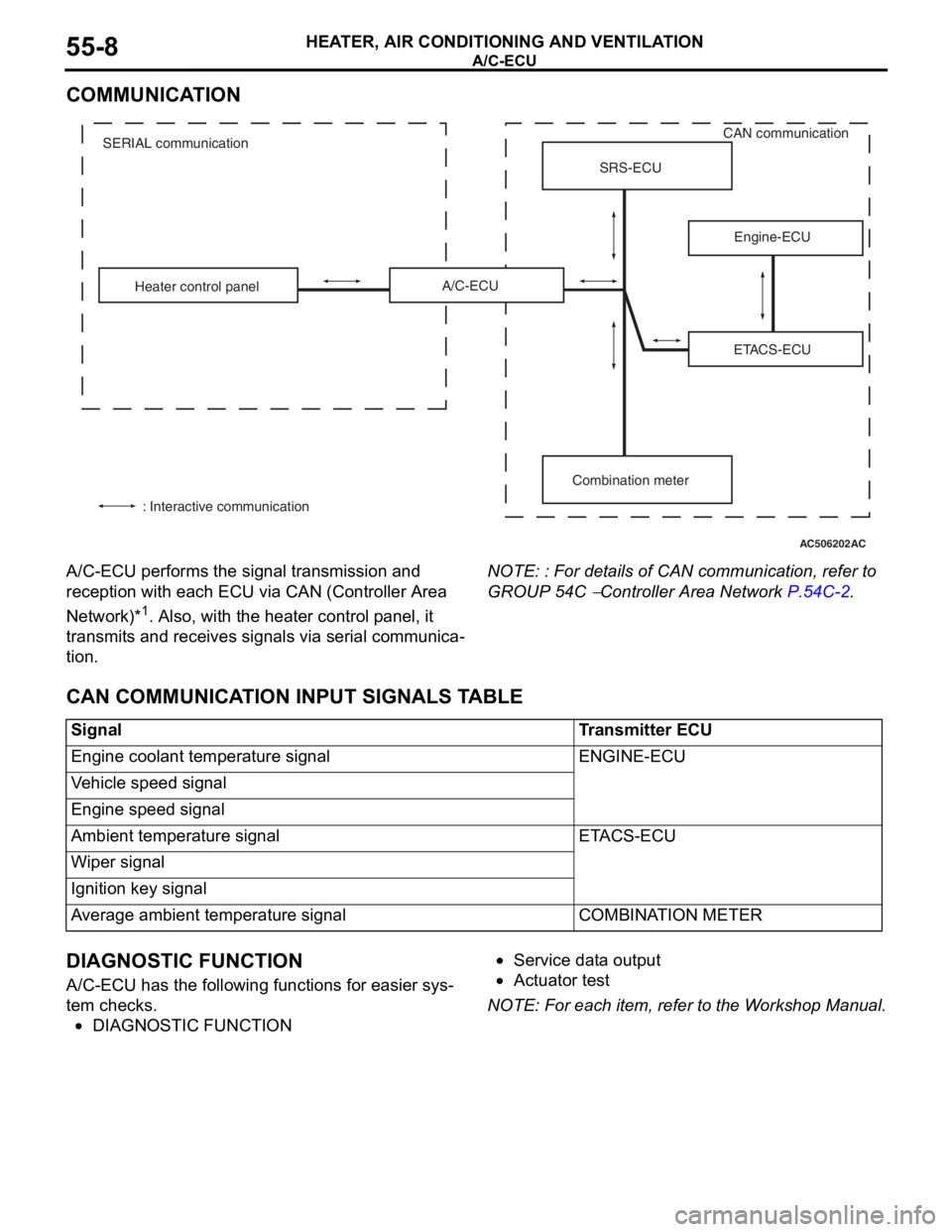
COMMUNICATION
A/C-ECU performs the signal transmission and
reception with each ECU via CAN (Controller Area
Network)*
1. Also, with the heater control panel, it
transmits and receives signals via serial communica
-
tion.
NOTE: : For details of CAN communication, refer to
GROUP 54C
− Controller Area Network P.54C-2.
CAN COMMUNICATION INPUT SIGNALS TABLE
DIAGNOSTIC FUNCTION
A/C-ECU has the following functions for easier sys-
tem checks.
•DIAGNOSTIC FUNCTION
•Service data output
•Actuator test
NOTE: For each item, refer to the Workshop Manual.
AC506202
ETACS-ECU Heater control panelSRS-ECU
Engine-ECU
Combination meter A/C-ECU
: Interactive communicationCAN communication
SERIAL communication
AC
SignalTransmitter ECU
Engine coolant temperature signalENGINE-ECU
Vehicle speed signal
Engine speed signal
Ambient temperature signalETACS-ECU
Wiper signal
Ignition key signal
Average ambient temperature signalCOMBINATION METER
Page 66 of 241

AUTO-CRUISE CONTROL SYSTEM
ENGINE AND EMISSION CONTROL17-4
COMPONENTS AND FUNCTIONS
ComponentFunction
Accelerator pedal position sensor (APP sensor)Informs the ECM of the accelerator pedal
depression.
Auto-cruise control switch"ON/OFF" switchPower switch for auto-cruise control system.
"ACC/RES" switchVehicle speed is set with the "ACC/RES" switch and
"COAST/SET" switch.
"COAST/SET" switch
"CANCEL" switchCancels the cruise speed setting.
Cancel systemClutch switch
the clutch operation, the clutch pedal status is
detected.
Stoplight switch•Because the constant speed driving is canceled
by the brake operation, it detects the brake pedal
status.
•As for the stoplight switch, two built-in switches,
the stoplight switch which is also used for the
stoplight illumination and the brake switch which
is used exclusively for the auto-cruise control, are
integrated, and thus the reliability is enhanced.
Transmission range
switch
the selector lever operation, it detects the "N"
position.
"CRUISE" indicator lightThe light is included in the combination meter and
illuminates when the "ON/OFF" switch is pressed
(auto-cruise control system: ON).
Data link connectorIf the M.U.T.-III scan tool is connected, the input
check code from the ECM can be read.
Engine control module (ECM)•Based on the input signal from each sensor and
switch, it outputs the throttle opening instruction
signal to the TAC motor.
•Based on the input signal from each sensor and
switch, it outputs the transaxle control signal to
the TCM
•Based on the vehicle speed signal from the
vehicle speed sensor, it calculates the vehicle
speed
•Based on the secondary pulley speed sensor
signal from the TCM, it calculates the vehicle
speed
•Based on the selector lever "N" position signal of
the transmission range switch from the ECM, it
cancels constant speed driving.
•Outputs the ON/OFF signals of "CRUISE"
indicator light and auto-cruise control system.
•The diagnostic trouble code signal is sent to the
"CRUISE" indicator light.
•The input check code is sent to the data link
connector.
Throttle actuator control motor (TAC motor)The throttle valve opens and closes in response to
the throttle angle signal from the ECM.
Page 68 of 241

AUTO-CRUISE CONTROL SYSTEM
ENGINE AND EMISSION CONTROL17-6
SYSTEM FUNCTIONS
.
SET FUNCTION
1. During driving with the vehicle speed range from
approximately 40 to 200 km/h (25 to 125 mph),
press and release the "COAST/SET" switch.
2. The vehicle speed when the "COAST/SET" switch
is released is memorized. Thereafter, the constant
speed driving is performed at that vehicle speed.
3. When the "COAST/SET" switch is operated
during the driving with the vehicle speed of
approximately 200 km/h (125 mph) or more, the
constant speed driving will not be performed.
.
COAST FUNCTION
1. When the "COAST/SET" switch is continuously
pressed for 0.5 seconds or longer during constant
speed driving, the throttle valve becomes fully
closed while the switch is pressed, and the
vehicle is decelerated.
2. When the "COAST/SET" switch is released, the
vehicle speed at that time is now memorized.
Thereafter, the constant speed driving is
performed at that vehicle speed.
3. Also when the "COAST/SET" switch is pressed
for less than 0.5 second, the vehicle is
decelerated 1.6 km/h (1 mph) from the vehicle
speed of constant speed driving, and the
decelerated vehicle speed is now memorized.
Thereafter, the constant speed driving is
performed at that vehicle speed.
4. When the "COAST/SET" switch is continuously
pressed and the vehicle speed is decelerated to
approximately 40 km/h (25 mph) or less, the set
function and coast function are cancelled, and the
constant speed driving is cancelled.
.
RESUME FUNCTION
1. When the "CANCEL" switch is pressed or the
brake pedal is depressed during the constant
speed driving, it cancels the constant speed
driving.
2. Subsequently, when the "ACC/RES" switch is
pressed during driving with the vehicle speed of
approximately 40 km/h (25 mph) or more, the
constant speed driving is performed with the
vehicle speed memorized at the last cancellation
of constant speed driving.
.
ACCEL FUNCTION
1. When the "ACC/RES" switch is continuously
pressed for 0.5 second or more during constant
driving, it accelerates the vehicle with specified
acceleration while the switch is pressed.
2. Then, when the "ACC/RES" switch is released,
the vehicle speed at that time is now memorized.
Thereafter, the constant speed driving is
performed at that vehicle speed.
3. Also, when the "ACC/RES" switch is pressed for
less than 0.5 second, the vehicle is accelerated
1.6 km/h (1 mph) from the vehicle speed of
constant speed driving, and the accelerated
vehicle speed is now memorized. Thereafter, the
constant speed driving is performed at that
vehicle speed.
4. It is possible to keep pressing the "ACC/RES"
switch until the vehicle speed is accelerated to
approximately 200 km/h (125 mph) or above.
However, after the "ACC/RES" switch is released,
the vehicle speed of approximately 200 km/h (125
mph) becomes the newly memorized vehicle
speed. Thereafter, the constant speed driving is
performed at that speed.
.
CANCEL FUNCTION
When any of the following conditions are satisfied,
the constant speed driving will be cancelled.
•The auto-cruise control system is stopped by the
pressing the "ON OFF" switch.
•The "CANCEL" switch is pressed.
•The brake pedal is depressed.
•The clutch pedal is depressed
•The selector lever is shifted to the "N" position
•The vehicle speed becomes approximately 40
km/h (25 mph) or less.
•The vehicle speed is reduced 15 km/h (9 mph) or
more from the speed at which the constant speed
driving was started.
•An abnormality occurs in the vehicle speed sig-
nal.
•The engine coolant temperature becomes abnor-
mally high.
•An abnormality occurs to the ECM.
•An abnormality occurs to the TCM
•An abnormality occurs to the CAN communica-
tion.
.
Page 113 of 241
SENSOR
MULTIPORT FUEL SYSTEM (MFI)13A-20
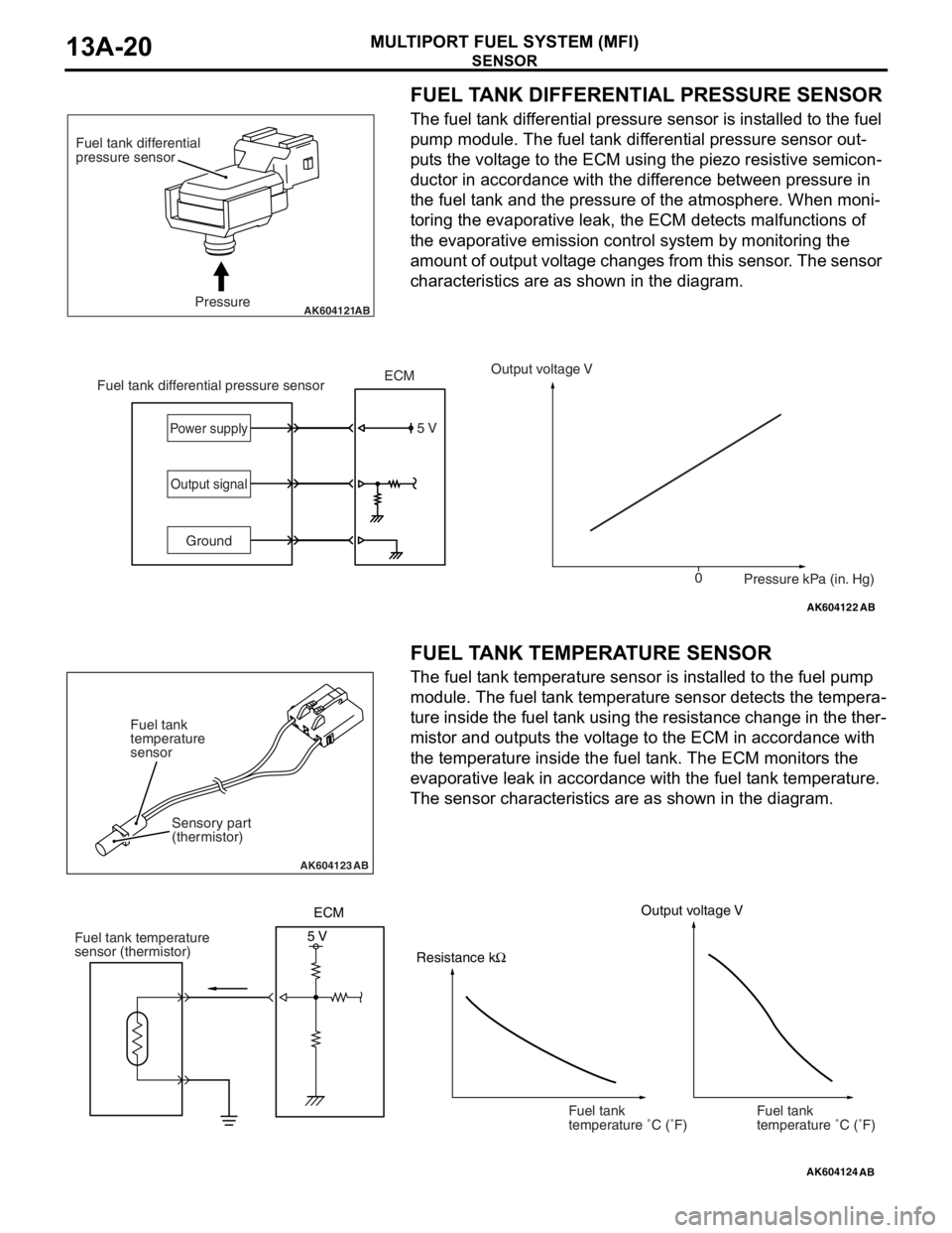
FUEL TANK DIFFERENTIAL PRESSURE SENSOR
The fuel tank differential pressure sensor is installed to the fuel
pump module. The fuel tank differential pressure sensor out
-
puts the voltage to the ECM using the piezo resistive semicon-
ductor in accordance with the difference between pressure in
the fuel tank and the pressure of the atmosphere. When moni
-
toring the evaporative leak, the ECM detects malfunctions of
the evaporative emission control system by monitoring the
amount of output voltage changes from this sensor. The sensor
characteristics are as shown in the diagram.
.
FUEL TANK TEMPERATURE SENSOR
The fuel tank temperature sensor is installed to the fuel pump
module. The fuel tank temperature sensor detects the tempera
-
ture inside the fuel tank using the resistance change in the ther-
mistor and outputs the voltage to the ECM in accordance with
the temperature inside the fuel tank. The ECM monitors the
evaporative leak in accordance with the fuel tank temperature.
The sensor characteristics are as shown in the diagram.
AK604121Pressure Fuel tank differential
pressure sensorAB
AK604122
5 V
0 GroundOutput voltage V
Pressure kPa (in. Hg) Fuel tank differential pressure sensorECMPower supply
Output signal
AB
AK604123AB
Sensory part
(thermistor) Fuel tank
temperature
sensor
AK604124
ECM
Resistance kΩOutput voltage V
5 V
AB
Fuel tank temperature
sensor (thermistor)
Fuel tank
temperature �C (�F)Fuel tank
temperature �C (�F)
Page 212 of 241

GENERAL INFORMATION
FOUR-WHEEL ANTI-LOCK BRAKE SYSTEM (4ABS)35B-3
MAIN COMPONENTS AND FUNCTIONS
.
Parts nameNo.Functional description
SensorWheel speed sensor1Outputs the frequency signal in proportion to the
rotation speed of each wheel to ABS-ECU.
Magnetic encoder for
wheel speed detection2The wheel speed sensor is a pulse generator. When
the magnetic encoder for wheel speed detection (a
plate on which north and south pole sides of the
magnets are arranged alternately) rotates, it outputs
frequency pulse signal in proportion to each wheel
speed.
Stop light switch3Outputs the signal indicating whether the brake pedal
is depressed or not through ETACS-ECU to ABS-ECU
via the CAN line.
ActuatorHydraulic unit4Drives the solenoid valve using the signal from
ABS-ECU, and controls the brake fluid pressure for
each wheel.
ABS warning light5Informs the driver of the system status by illuminating,
flashing, or turning off the warning light according to
the signal from ABS-ECU.
Brake warning light6Used as the warning light for the parking brake, brake
fluid level, and EBD control. Informs the driver of the
system status by illuminating or turning off the warning
light according to the signal from ABS-ECU, ETACS or
combination meter.
Data link connector7Establishes the communication with scan tool.
ABS control unit (ABS-ECU)8Controls the actuators (described above) based on the
signals coming from each sensors.
Controls the self-diagnostic functions and fail-safe
functions.
Controls diagnostic function (Compatible with scan
tool).
Page 216 of 241
CONSTRUCTION DESCRIPTION
FOUR-WHEEL ANTI-LOCK BRAKE SYSTEM (4ABS)35B-7
ABS-ECUM2351003000520
•By integrating ABS-ECU into the hydraulic unit,
no wiring harness for sending drive signal of the
solenoid valve and pump motor is required,
assuring higher reliability.
•Self-diagnostic and memory functions are inte-
grated into ABS-ECU. If any malfunction is
detected by the self-diagnostic function,
ABS-ECU activates a fail-safe function and illumi
-
nates the ABS warning light and brake warning
light
*.
NOTE: *: The brake warning light is used as the
EBD control warning light.
•ABS-ECU detects vehicle speed from the signals
of the wheel speed sensor and its recognizes the
wheel rotation status, estimates the wheel slip
condition based on the preprogrammed algo
-
rithm, and then controls the solenoid valve in the
hydraulic unit so that the wheels do not lock.
ABS hydraulic pressure control
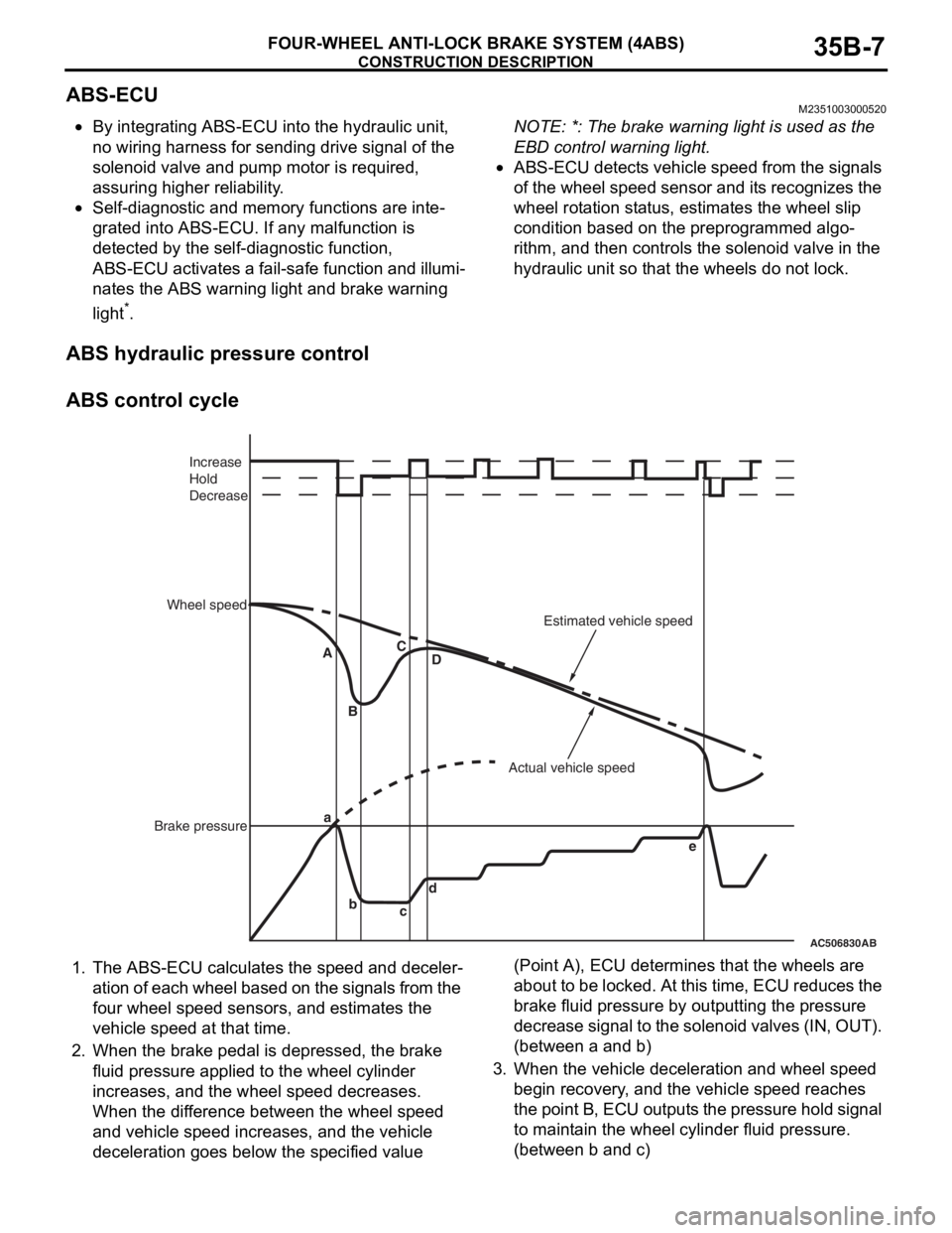
ABS control cycle
1. The ABS-ECU calculates the speed and deceler-
ation of each wheel based on the signals from the
four wheel speed sensors, and estimates the
vehicle speed at that time.
2. When the brake pedal is depressed, the brake
fluid pressure applied to the wheel cylinder
increases, and the wheel speed decreases.
When the difference between the wheel speed
and vehicle speed increases, and the vehicle
deceleration goes below the specified value (Point A), ECU determines that the wheels are
about to be locked. At this time, ECU reduces the
brake fluid pressure by outputting the pressure
decrease signal to the solenoid valves (IN, OUT).
(between a and b)
3. When the vehicle deceleration and wheel speed
begin recovery, and the vehicle speed reaches
the point B, ECU outputs the pressure hold signal
to maintain the wheel cylinder fluid pressure.
(between b and c)
AC506830AB
a
b
cd A
BC
D
e Increase
Hold
Decrease
Wheel speed
Brake pressureActual vehicle speedEstimated vehicle speed
Page 217 of 241
CONSTRUCTION DESCRIPTION
FOUR-WHEEL ANTI-LOCK BRAKE SYSTEM (4ABS)35B-8
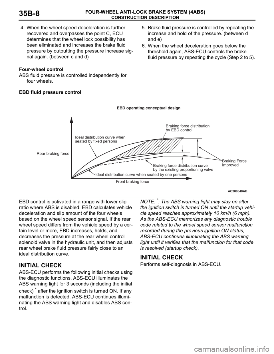
4. When the wheel speed deceleration is further
recovered and overpasses the point C, ECU
determines that the wheel lock possibility has
been eliminated and increases the brake fluid
pressure by outputting the pressure increase sig
-
nal again. (between c and d)
5. Brake fluid pressure is controlled by repeating the
increase and hold of the pressure. (between d
and e)
6. When the wheel deceleration goes below the
threshold again, ABS-ECU controls the brake
fluid pressure by repeating the cycle (Step 2 to 5).
Four-wheel control
ABS fluid pressure is controlled independently for
four wheels.
EBD fluid pressure control
EBD control is activated in a range with lower slip
ratio where ABS is disabled. EBD calculates vehicle
deceleration and slip amount of the four wheels
based on the wheel speed sensor signal. If the rear
wheel speed differs from the vehicle speed by a cer
-
tain level or more, EBD increases, holds, and
decreases the pressure at the rear wheel control
solenoid valve in the hydraulic unit, and then adjusts
rear wheel brake fluid pressure fairly close to an
ideal distribution curve.
INITIAL CHECK
ABS-ECU performs the following initial checks using
the diagnostic functions. ABS-ECU illuminates the
ABS warning light for 3 seconds (including the initial
check)
* after the ignition switch is turned ON. If any
malfunction is detected, ABS-ECU continues illumi
-
nating the ABS warning light and disables ABS con-
trol.
NOTE: *: The ABS warning light may stay on after
the ignition switch is turned ON until the startup vehi
-
cle speed reaches approximately 10 km/h (6 mph).
As the ABS-ECU memorizes any diagnostic trouble
code related to the wheel speed sensor malfunction
recorded during the previous ignition ON status,
ABS-ECU continues illuminating the ABS warning
light until it verifies that the malfunction for that code
is resolved (startup check).
.
INITIAL CHECK
Performs self-diagnosis in ABS-ECU.
AC208548AB
Ideal distribution curve when
seated by fixed personsEBD operating conceptual design
Rear braking force
Ideal distribution curve when seated by one personsBraking force distribution curve
by the existing proportioning valveBraking force distribution
by EBD control
Front braking forceBraking Force
Improved