abs MITSUBISHI LANCER EVOLUTION X 2008 Owner's Manual
[x] Cancel search | Manufacturer: MITSUBISHI, Model Year: 2008, Model line: LANCER EVOLUTION X, Model: MITSUBISHI LANCER EVOLUTION X 2008Pages: 241, PDF Size: 8.26 MB
Page 160 of 241
TRIMS
INTERIOR52A-11
DOOR TRIMM2520012300594
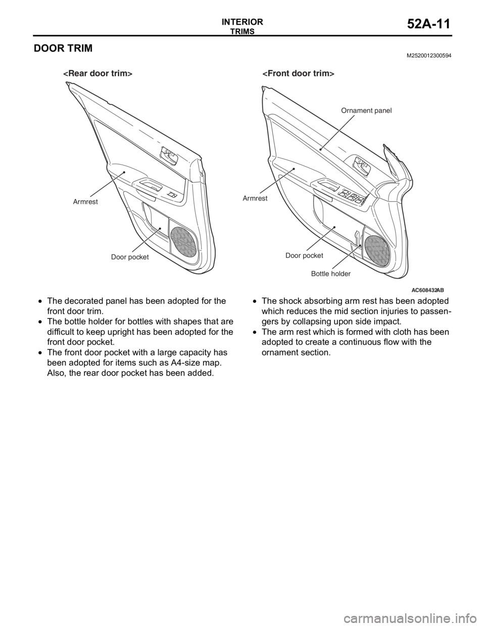
•The decorated panel has been adopted for the
front door trim.
•The bottle holder for bottles with shapes that are
difficult to keep upright has been adopted for the
front door pocket.
•The front door pocket with a large capacity has
been adopted for items such as A4-size map.
Also, the rear door pocket has been added.
•The shock absorbing arm rest has been adopted
which reduces the mid section injuries to passen
-
gers by collapsing upon side impact.
•The arm rest which is formed with cloth has been
adopted to create a continuous flow with the
ornament section.
AC608432
Door pocketDoor pocket
Armrest
Bottle holder
Armrest
Ornament panel
AB
Page 161 of 241
HEADLINING
INTERIOR52A-12
HEADLININGM2520014000306
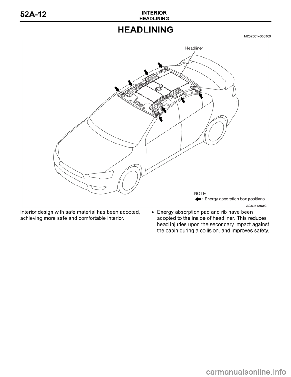
Interior design with safe material has been adopted,
achieving more safe and comfortable interior.•Energy absorption pad and rib have been
adopted to the inside of headliner. This reduces
head injuries upon the secondary impact against
the cabin during a collision, and improves safety.
AC608128AC
NOTE
: Energy absorption box positions
Headliner
Page 174 of 241
DOOR TRIM
TSB Revision
INTERIOR52A-13
DOOR TRIM
REMOVAL AND INSTALLATIONM1521006400752
Required Special Tool:
•MB990784: Ornament Remover
AC611164
15
7
12 6
2
8
9
10 11
3
4
A
Section A – A
Note
: Clip positions
A
Clip
Front door trim
assembly
AB
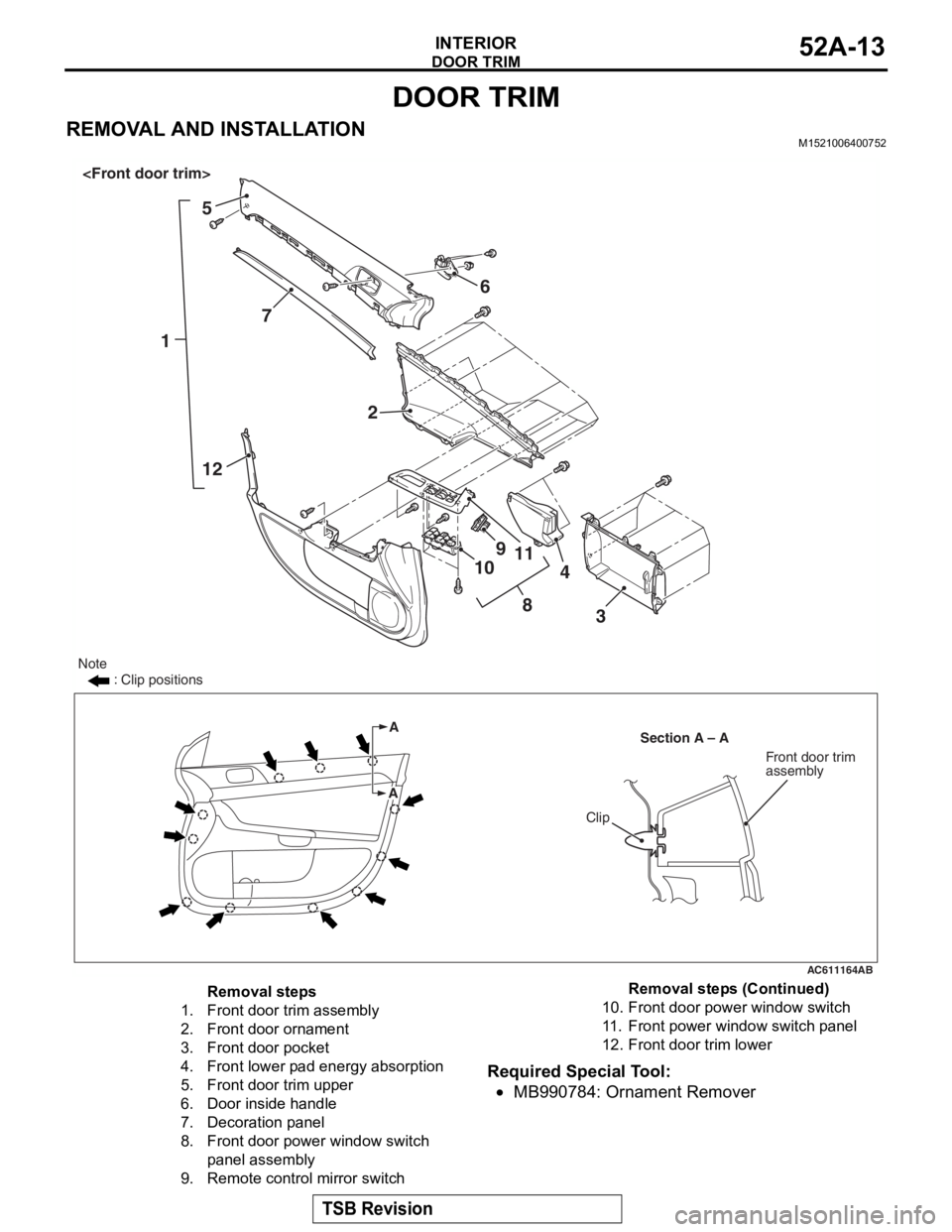
Removal steps
1.Front door trim assembly
2.Front door ornament
3.Front door pocket
4.Front lower pad energy absorption
5.Front door trim upper
6.Door inside handle
7.Decoration panel
8.Front door power window switch
panel assembly
9.Remote control mirror switch
10.Front door power window switch
11 .Front power window switch panel
12.Front door trim lower
Removal steps (Continued)
Page 175 of 241
DOOR TRIM
TSB Revision
INTERIOR52A-14
Required Special Tool:
•MB990784: Ornament Remover
AC611175
A
ASection A – A
Clip
Rear door trim
assembly
16
11 2
3
8
10
9 5
4
NOTE : Clip positions
AB
7
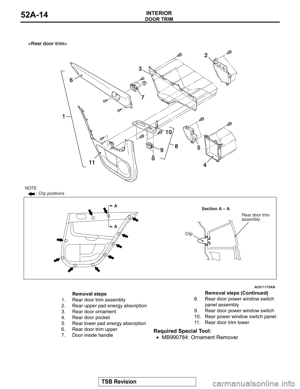
Removal steps
1.Rear door trim assembly
2.Rear upper pad energy absorption
3.Rear door ornament
4.Rear door pocket
5.Rear lower pad energy absorption
6.Rear door trim upper
7.Door inside handle
8.Rear door powe r window switch
panel assembly
9.Rear door powe r window switch
10.Rear power window switch panel
11 .Rear door trim lower
Removal steps (Continued)
Page 177 of 241

HEADLINING
TSB Revision
INTERIOR52A-16
Required Special Tool:
•MB990784: Ornament Remover
REMOVAL SERVICE POINTS
.
<> SUN VISOR HOLDER REMOVAL
Insert the special tool MB990784 into side claws of the sun
visor holder through the both sides of the sun visor holder to
remove the hinges.
.
<> HEADLINING ASSEMBLY REMOVAL
To remove the clip, insert a vinyl cord into a clearance between
the clip and the headlining, and pass it around the clip. Then,
pull out the clip downwards while pulling the vinyl cord.
Removal steps
1.Assist grip
2.Rear dome light assembly
3.Front dome light
4.Sun visor assembly
<>5.Sun visor holder
6.Sunroof lid inner weather strip rear
<>7.Headlining
8.Assist grip bracket
9.Front side roof energy absorption box
10.Rear side roof energy absorption box
Removal steps (Continued)
AC005512
MB990784
MB990784
Sun visor holder
AF
AC600751AD
Clip
Headlining Vinyl cord
Page 195 of 241

GENERAL INFORMATION
FRONT AXLE26-2
GENERAL INFORMATIONM2260000100819
For the front axle, a double-row angular contact ball
bearing with an integral oil seal is adopted as a
wheel bearing, and EBJ-ETJ type constant velocity
joint as a driveshaft.
It has the following features:
•The driveshaft incorporates lightweight and com-
pact EBJ-ETJ type constant velocity joints.
•Lead-free grease for the constant velocity joint is
adopted.
•Hexavalent chromium is eliminated from the dust
cover material.
•The number of parts is reduced by integrating the
magnetic encoder for ABS wheel speed detection
into the wheel bearing.
NOTE: .
ETJ (High Efficiency Compact Tripod Joint): the
lighter and smaller constant velocity joint com
-
pared with the conventional TJ has been
installed.
EBJ (High Efficiency Compact Birfield Joint): the
lighter and smaller constant velocity joint com
-
pared with the conventional BJ has been
achieved by adopting the eight small balls.
SPECIFICATIONS
NOTE: *: Indicates the distance between each joint
center.
ItemSpecification
Wheel bearingBearing typeUnit bearing (double-row angular contact ball
bearing)
Bearing (Outer diameter x inside
diameter) mm (in)80 × 43 (3.15 × 1.69)
DriveshaftJoint typeOutsideEBJ
InsideETJ
Shaft length* x shaft
diameter mm (in)M/T-LH380.5 × 24.5 (15.0 × 1.0)
M/T-RH715 × 28 (28.1 × 1.1)
CVT-LH399.5 × 24.5 (15.7 × 1.0)
CVT-RH715.0 × 28 (28.1 × 1.1)
Page 201 of 241

GENERAL
BASIC BRAKE SYSTEM35A-2
GENERALM2350000100956
Brake systems with higher reliability and durability
have achieved distinguished braking performance.
FEATURES
.
IMPROVEMENT OF BRAKING PERFOR-
MANCE
•A 10-inch single brake booster with the variable
boost ratio mechanism has been used to assure
maximum braking force with less pedal pressure
in case of emergency.
•In addition to the 10-inch single brake booster, a
small and long stroke-type master cylinder has
been adopted to achieve downsizing and secure
assist force.
•15-inch or 16-inch ventilated disc brakes have
been adopted for the front.
•8-inch leading trailing-type drum brake, 14-inch
or 16-inch solid disc brake has been adopted for
the rear.
.
IMPROVEMENT IN SAFETY
•The 4-wheel anti-lock brake system (4ABS) has
been installed to prevent slippage resulting from
the wheel lock and assure stable vehicle posture
and driveability.
•A rear wheel early lock-prevention proportioning
valve has been used.
•Electronic control braking force distribution sys-
tem (EBD) has been adopted to assure the maxi-
mum braking force independently of the
passenger's position in the vehicle.
•X-type piping of brake lines have been adopted
for the front and rear wheels.
•Audible wear indicators are used on the front and
rear brake pads to warn the driver of wear limit.
.
SERVICE QUALITY IMPROVEMENTS
•Diagnostic function has been adopted to ABS for
easier inspection.
•Brake fluid reservoir, master cylinder, and brake
booster have been integrated for downsizing and
better serviceability.
Page 202 of 241
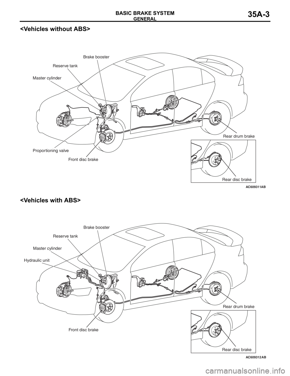
GENERAL
BASIC BRAKE SYSTEM35A-3
AC609311AB
Brake booster
Master cylinder
Proportioning valve
Front disc brake
Reserve tank
Rear drum brake
Rear disc brake
AC609312AB
Brake booster
Master cylinder
Hydraulic unit
Front disc brake
Rear drum brake
Rear disc brake
Reserve tank
Page 203 of 241

GENERAL
BASIC BRAKE SYSTEM35A-4
SPECIFICATIONS
ItemSpecifications
Master cylinderTy p eTandem type
I.D. mm (in)20.6 (0.81)
Brake boosterTy p eVacuum type, single
Effective dia. of power cylinder mm (in)254 (10.0)
Boost ratioVehicles without ABS6.5 (Pedal pressure: 188N)
Vehicles with ABS6.5 (Pedal pressure: 92N)
8.5 (Pedal pressure: 156N)
Rear wheel hydraulic control typeVehicles without ABSProportioning valves
Vehicles with ABSElectronic control braking force
distribution system (EBD)
Front disc brakeTy p eVehicles with 16-inch wheelFloating caliper 1 piston
ventilated disc (V5-S57)
Vehicles with 18-inch wheelFloating caliper 1 piston
ventilated disc (V6-S57)
Disc effective dia ×
thickness mm (in)Vehicles with 16-inch wheel222 × 26 (8.7 × 1.02)
Vehicles with 18-inch wheel241.6 × 26 (9.5 × 1.02)
Cylinder I.D. mm (in)57.1 (2.25)
Pad thickness mm (in)10.0 (0.39)
Clearance adjustmentAutomatic adjustment
Rear drum brakeTy p eLeading trailing drum
Drum I.D. mm (in)203 (8.0)
Wheel cylinder I.D. mm (in)19.0 (0.75)
Lining thickness mm (in)4 (0.157)
Clearance adjustmentAutomatic
Rear disc brakeTy p eVehicles with 16-inch wheelFloating caliper 1 piston solid disc
(S4-S35)
Vehicles with 18-inch wheelFloating caliper 1 piston solid disc
(S6-S35)
Disc effective dia ×
thickness mm (in)Vehicles with 16-inch wheel226 × 10 (8.9 × 0.39)
Vehicles with 18-inch wheel258 × 10 (10.2 × 0.39)
Cylinder I.D. mm (in)34.9 (1.37)
Pad thickness mm (in)10.0 (0.39)
Clearance adjustmentAutomatic adjustment
Page 209 of 241
CONSTRUCTION DESCRIPTION
BASIC BRAKE SYSTEM35A-10
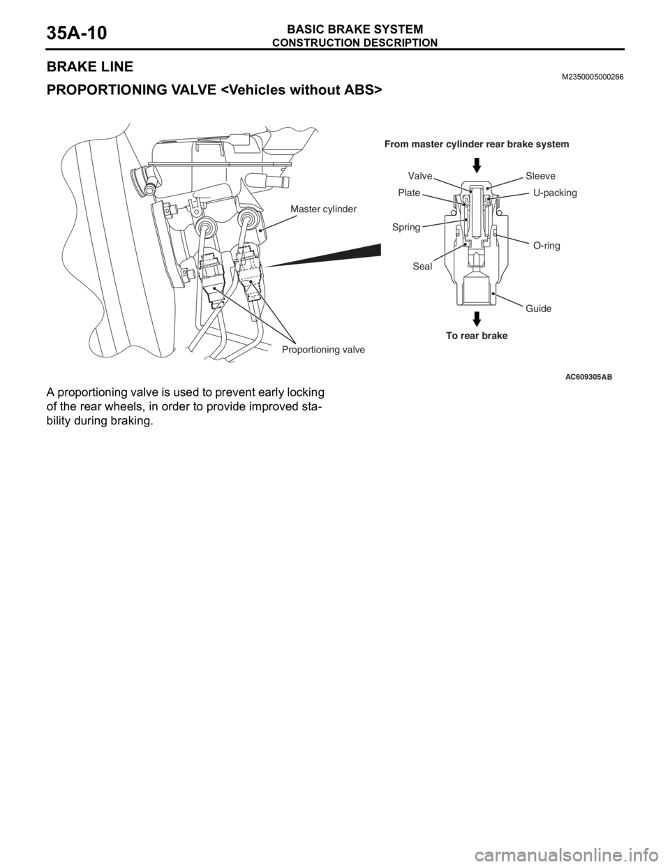
BRAKE LINEM2350005000266
PROPORTIONING VALVE
A proportioning valve is used to prevent early locking
of the rear wheels, in order to provide improved sta
-
bility during braking.
AC609305
From master cylinder rear brake system
To rear brakeO-ring U-packing Sleeve
Guide Seal
Proportioning valveMaster cylinder
SpringPlateValve
AB