sensor MITSUBISHI LANCER IX 2006 Service Manual
[x] Cancel search | Manufacturer: MITSUBISHI, Model Year: 2006, Model line: LANCER IX, Model: MITSUBISHI LANCER IX 2006Pages: 800, PDF Size: 45.03 MB
Page 20 of 800

TROUBLESHOOTING
ENGINE COOLING14-6
INSPECTION PROCEDURE FOR
TROUBLE SYMPTOMS
INSPECTION PROCEDURE 1: Cooling Fan (L.H.) and Cooling Fan (R.H.) <4G1 (Vehicles with A/C)> or
A/C Condenser Fan <4G6> do not Operate
Wire colour code
B : Black LG : Light green
G : Green L : Blue
W : White Y : Yellow
SB : Sky blue BR : Brown
O : Orange GR : Gray
R : Red P : Pink V : Violet
FAN CONTROL
RELAY
A-09XENGINE CONTROL
RELAY
B-16X
AC303577
A-18-1
COOLING FAN
MOTOR (L.H.)
COOLING FAN
MOTOR (R.H.)
<4G1 (VEHICLES
WITH A/C>
OR
A/C CONDENSER
FAN MOTOR <4G6> A-18-2
A-18
COOLING FAN
MOTOR DRIVE
CONTROL UNIT 1 A-13
12 C-111
ENGINE-ECU
ENGINE-A/T-ECU
21 C-123
18 C-122
615 121179
810234
(MU802322)
(MU801824)
C-123
(MU803784)C-122
(MU802611)A-13
C-111 L
L 2
22 11
1B
L
2
3
4
B-W
FUSIBLE
LINK No.2
B3
1
R-Y
R-Y
8 A-13
11 C-111
615 121179
810234
(MU802611)
J/C (6)
C-12
C-134
R-Y
3328
A-13
C-111
Cooling Fan (L.H.) and Cooling Fan (R.H.) or A/C Condenser Fan Drive Circut
AB
CIRCUIT OPERA T ION
•The cooling fan motor drive contro l unit is pow-
ered from fusible link (2).
•The engine-ECU
water t
e mpe r ature sensor unit and the vehicle
speed sensor
senso
r to control the speed of the coo ling
fan
moto r (L.H.) and the cooling fa n mot o r (R.H.)
<4G1 (V
ehicles wit h A/C)> or A/C co ndenser fan
motor <4G6>.
Page 21 of 800
TROUBLESHOOTING
ENGINE COOLING14-7
•The engine-ECU
controls the cooling fan motor drive control
unit to activate the cooling fan motor (L.H.) and
the cooling fan motor (R.H.) <4G1 (Vehicles with
A/C)> or A/C condenser fan motor <4G6>.
TECHNICAL DESCRIPTION
•The cause could be a malfunction of the cooling
fan motor drive control unit power supply or earth
circuit.
•If the communication line wiring harness between
the cooling fan motor drive control unit and the
engine-ECU
short-circuited to earth, the cooling fan motor
(L.H.) and the cooling fan motor (R.H.) <4G1
(Vehicles with A/C)> or the A/C condenser fan
motor <4G6> will not rotate.
•The cause could also be a malfunction of the
cooling fan motor (L.H.).
•The cause could also be a malfunction of imput
signal from the A/C switch, the water temperature
sensor unit and the vehicle speed sensor
or the output shaft speed sensor to the
engine-ECU
•The cause could also be a malfunction of the
cooling fan motor drive control unit or the
engine-ECU
TROUBLESHOOTING HINTS
•Malfunction of fusible link (2)
•Malfunction of fan control relay
•Malfunction of cooling fan motor (L.H.)
•Malfunction of cooling fan motor drive control unit
•Malfunction of engine-ECU
engine-A/T-ECU
•Damaged wiring harness or connector
DIAGNOSIS
STEP 1. Check the cooling fan motor (L.H.).
Refer to P.14-24.
Q: Is the cooling fan motor (L.H.) in good condition?
YES : Go to Step 2 .
NO : Replace the cooling fan motor (L.H.) (Refer
to
P.14-33) <4G1> (Refer to P.14-35)
<4G6>. Then go to Step 24 .
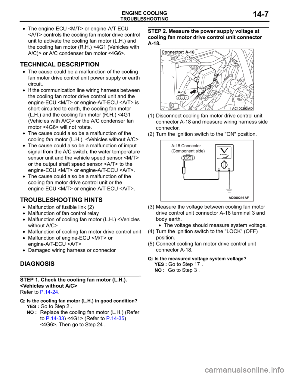
STEP 2. Measure the power supply voltage at
cooling fan motor drive control unit connector
A-18.
AC100293
A-18
321
Connector: A-18
AD
(1)D isconn ect cooling f an motor drive contro l unit
conne ctor A-18 a nd measure wirin g har ness side
connector .
(2)T urn t he ig nition switch t o the "ON" positio n.
AC000246AF
A-18 Connector
(Component side)
(3)M easu r e the volt age between cooling fan motor
drive control unit con nect o r A-18 te rmin al 3 a nd
bod y ea rth.
•The voltage shou ld measu r e syste m volt age.
(4)T urn t he ig nition switch t o the "L OCK" (OF F )
position.
(5)C onne ct cooling fa n mot o r drive control unit
connector A-18.
Q:Is t h e mea s ure d volt a g e sy ste m v o lt ag e?
YES : Go to S t ep 1 7 .
NO : Go to S t ep 3 .
Page 30 of 800
TROUBLESHOOTING
ENGINE COOLING14-16
INSPECTION PROCEDURE 2: Cooling Fan (L.H.) and Cooling Fan (R.H.) <4G1 (Vehicles with A/C)> or
A/C Condenser Fan <4G6> do not Change Speed or Stop
COOLING FAN (L.H.) AND COOLING FAN
(R.H.) OR A/C CONDENSER FAN DRIVE
CIRCUIT
Refer to P.14-6.
CIRCUIT OPERATION
Refer to P.14-6.
TECHNICAL DESCRIPTION
•If the communication line wiring harness between
the cooling fan motor drive control unit and the
engine-ECU
is open, the cooling fan motor (L.H.) and
the cooling fan motor (R.H.) <4G1 (Vehicles with
A/C)>, or the A/C condenser fan motor <4G6>
rotate to prevent the engine from overheating.
•If the system voltage is continuously supplied to
the cooling fan motor drive control unit by a fan
motor relay malfunction and a short circuit on the
cooling fan motor drive control unit power supply
wiring harness, the cooling fan motor (L.H.) and
the cooling fan motor (R.H.) <4G1 (Vehicles with
A/C)>, or the A/C condenser fan motor <4G6>
rotate.
•The cause could also be a malfunction of the
cooling fan motor (L.H.).
•The cause could also be a malfunction of input
signal from the A/C switch, the water temperature
sensor unit and the vehicle speed sensor
or the output shaft speed sensor to the
engine-ECU
•The cause could also be a malfunction of the
cooling fan motor drive control unit or the
engine-ECU
TROUBLESHOOTING HINTS
•Malfunction of fan control relay
•Malfunction of cooling fan motor (L.H.)
•Malfunction of cooling fan motor drive control unit
•Malfunction of engine-ECU
engine-A/T-ECU
•Damaged wiring harness or connector
DIAGNOSIS
STEP 1. Check the fan control relay.
Refer to P.14-23.
Q: Is the fan control relay in good condition?
YES : Go to Step 2 .
NO : Replace the fan control relay. Then go to
Step 8
.
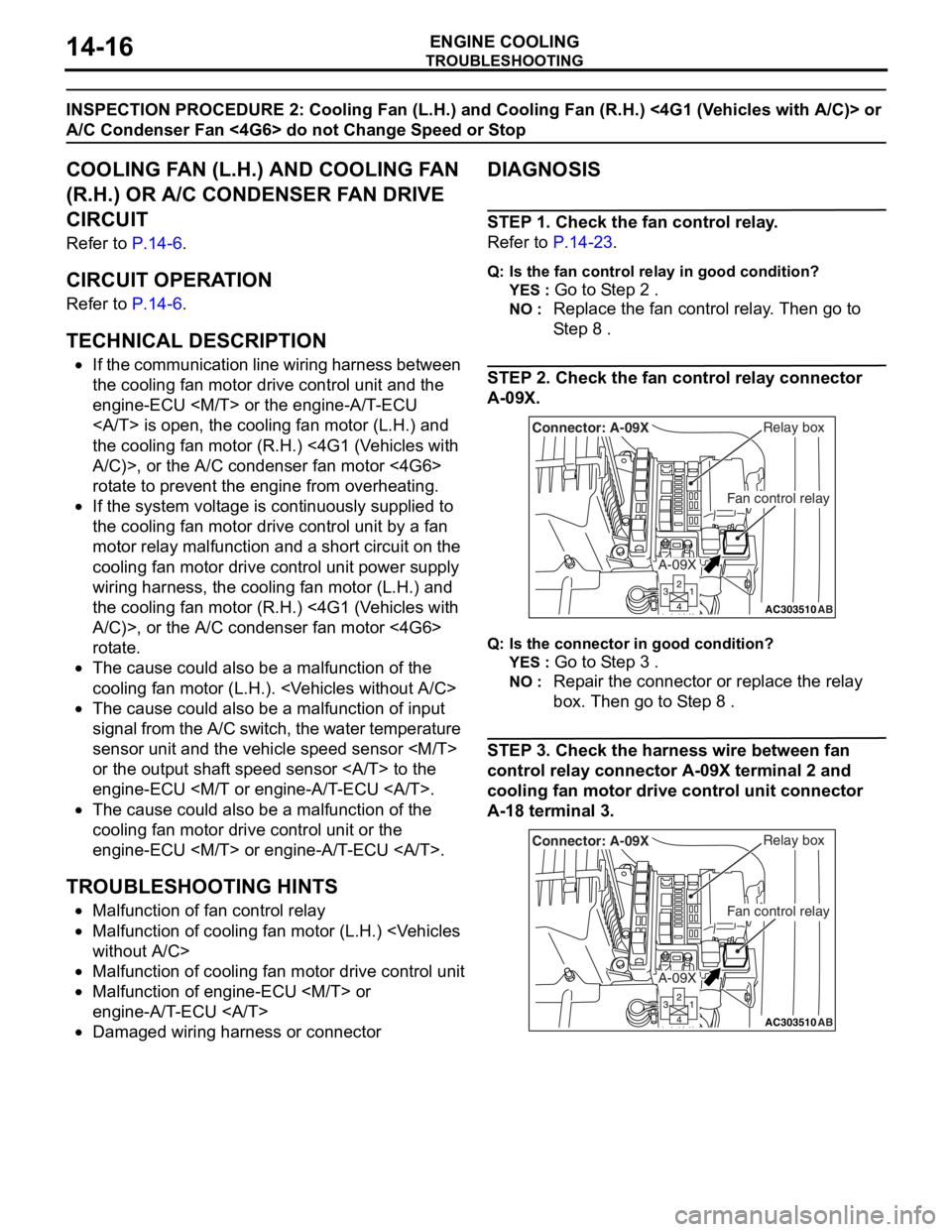
STEP 2. Check the fan control relay connector
A-09X.
AC303510AB
Fan control relay
Relay boxConnector: A-09X
A-09X
Q:Is t h e con n ec tor in goo d c ond it io n?
YES : Go to S t ep 3 .
NO : Repa ir th e con nect o r or rep l ace the re lay
box. Then
go to S t ep 8
.
STEP 3 . Check the harness wire be twee n fan
control relay
connec tor A-0 9 X terminal 2 and
cooling f
an motor drive control uni t connec tor
A-1
8 terminal 3.
AC303510AB
Fan control relay
Relay boxConnector: A-09X
A-09X
Page 39 of 800
AC301429
1
2 36
7
13 ± 2 N·m
AD
5
<4G6>
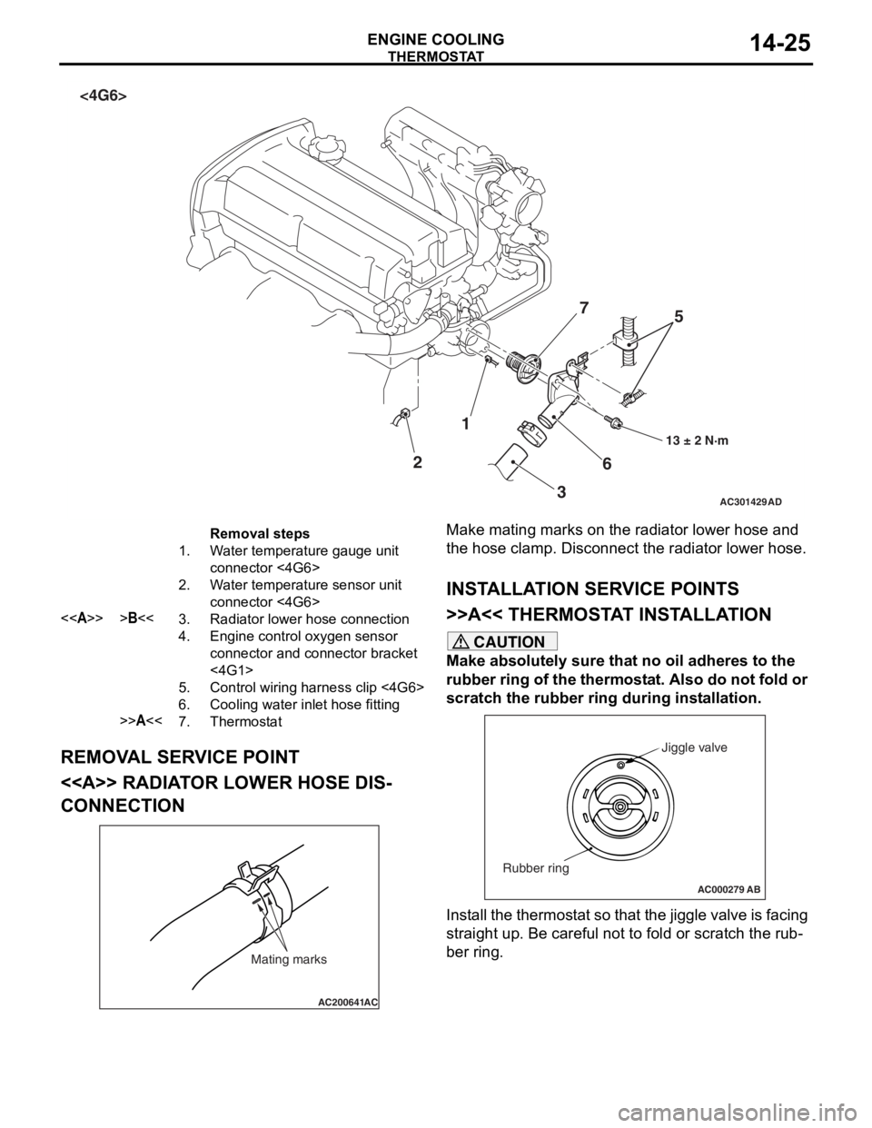
Removal steps
1.Water temperature gauge unit
connector <4G6>
2.Water temperature sensor unit
connector <4G6>
<>>B<<3.Radiator lower hose connection
4.Engine control oxygen sensor
connector and connector bracket
<4G1>
5.Control wiring harness clip <4G6>
6.Cooling water inlet hose fitting
>>A<<7.Thermostat
THERMOST
A T
ENGINE COOLING14-25
REMOV A L SER V ICE POINT
<> RADIAT OR LOW E R HOSE DIS-
CONNECTION
AC200641AC
Mating marks
Make mating marks on the rad i ator lower ho se an d
the hose clamp. Disconn
ect t he radiator lower hose.
INSTALLA T ION SER VICE POINTS
>>A<< THERMOSTA T INST ALLA TION
CAUTION
Make absolutely sure that no oil adheres to the
rubber ring of the thermostat. Also do not fold or
scratch the rubber ring during installation.
AC000279
Jiggle valve
Rubber ring
AB
Install the thermostat so that the jiggle valve is facing
straight up. Be careful not to fold or scratch the rub
-
ber ring.
Page 43 of 800
WATER HOSE AND WATER PIPE
ENGINE COOLING14-29
WATER HOSE AND WATER PIPE
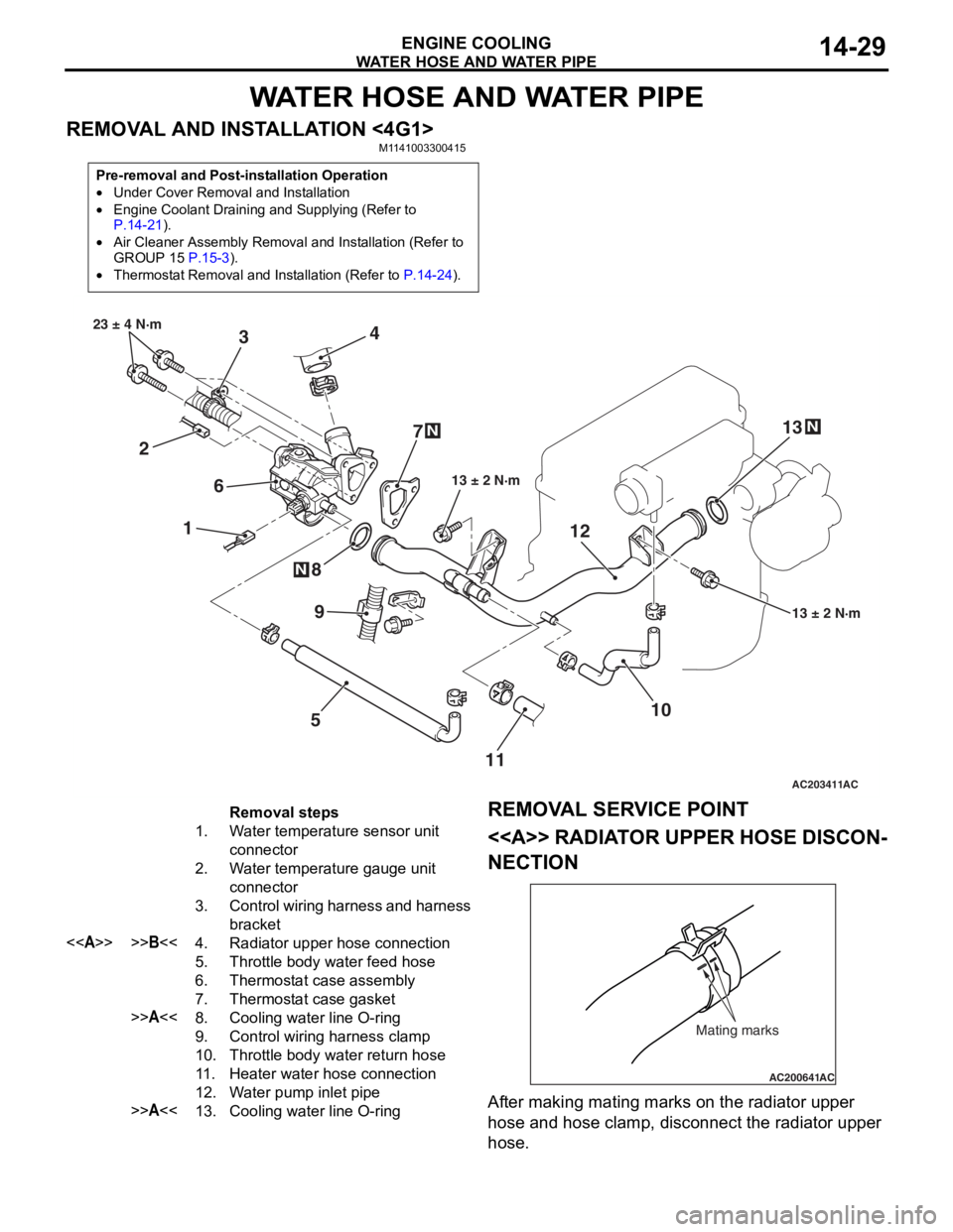
REMOVAL AND INSTALLATION <4G1>M1141003300415
Pre-removal and Post-installation Operation
•Under Cover Removal and Installation
•Engine Coolant Draining and Supplying (Refer to P.14-21).
•Air Cleaner Assembly Removal and Installation (Refer to
GROUP 15 P.15-3).
•Thermostat Removal and Installation (Refer to P.14-24).
AC203411
1
2 3
4
5
6
7
8
10
9
13 ± 2 N·m
23 ± 4 N·m
13 ± 2 N·m
N
N
AC
1112
13
N
Removal steps
1.Water temperature sensor unit
connector
2.Water temperature gauge unit
connector
3.Control wiring harness and harness
bracket
<>>>B<<4.Radiator upper hose connection
5.Throttle body water feed hose
6.Thermostat case assembly
7.Thermostat case gasket
>>A<<8.Cooling water line O-ring
9.Control wiring harness clamp
10.Throttle body water return hose
11 .Heater water hose connection
12.Water pump inlet pipe
>>A<<13.Cooling water line O-ring
REMOV
A L SER VICE POINT
<> RADIAT OR UPPER HOSE DISCON-
NECTION
AC200641AC
Mating marks
After making matin g ma rks on the radia t or upp er
hose
and h o se clamp, disconnect the radia t or upp er
hose
.
Page 52 of 800
GENERAL INFORMATION
INTAKE AND EXHAUST15-2
GENERAL INFORMATION
M1151000100402
The exhaust pipe is divided into three parts.
SERVICE SPECIFICATION
M1151000300428
ItemStandard valueLimit
Manifold distortion of the installation surface mm0.15 or less0.20
SPECIAL TOOL
M1151000600399
ToolNumberNameUse
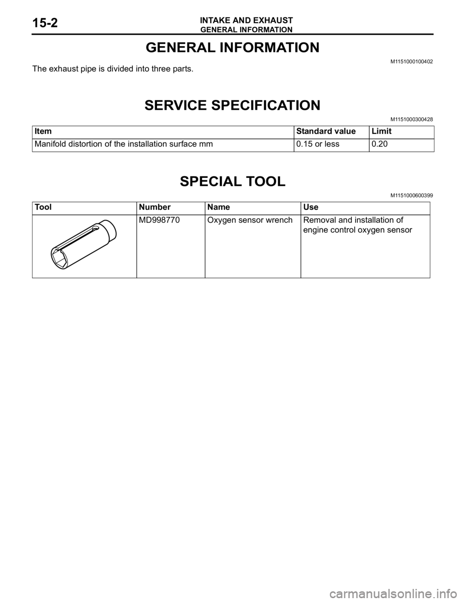
MD998770Oxygen sensor wrenchRemoval and installation of
engine control oxygen sensor
Page 54 of 800
AC303619
4.0 ± 1.0 N·m
4.0 ± 1.0 N·m10*
9* 4
1* 5
11
12 ± 1 N·m 9.0 ± 1.0 N·m
9.0 ± 1.0 N·m
AB
12 ± 1 N·m
Clamp
8*
3*
<4G6>
6
7
N
2
8.8 ± 1.0 N·m
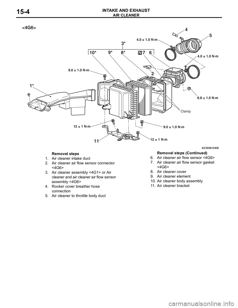
Removal steps
1.Air cleaner intake duct
2.Air cleaner air flow sensor connector
<4G6>
3.Air cleaner assembly <4G1> or Air
cleaner and air cleaner air flow sensor
assembly <4G6>
4.Rocker cover breather hose
connection
5.Air cleaner to throttle body duct
6.Air cleaner air flow sensor <4G6>
7.Air cleaner air flow sensor gasket
<4G6>
8.Air cleaner cover
9.Air cleaner element
10.Air cleaner body assembly
11 .Air cleaner bracket
AIR CLEA NER
INTAKE AN D EXHAU ST15-4
Removal steps (Continued)
Page 55 of 800
INLET MANIFOLD
INTAKE AND EXHAUST15-5
INLET MANIFOLD
REMOVAL AND INSTALLATION <4G1>M1151003000749
Pre-removal Operation
•Fuel Line Pressure Reduction (Refer to GROUP 13A -
On-vehicle Service
P.13A-372).
•Engine Coolant Draining (Refer to GROUP 14 - On-vehi-
cle Service P.14-21).
•Strut Tower Bar Removal (Refer to GROUP 42 P.42-9).
•Throttle Body Assembly Re moval (Refer to GROUP 13A
P.13A-383).
•Fuel Delivery Pipe and Fuel Injector Assembly Removal
(Refer to GROUP 13A
P.13A-381).
Post-installation Operation
•Fuel Delivery Pipe and Fuel Injector Assembly Installation
(Refer to GROUP 13A
P.13A-381).
•Throttle Body Assembly Inst allation (Refer to GROUP
13A
P.13A-383).
•Strut Tower Bar Installati on (Refer to GROUP 42 P.42-9).
•Engine Coolant Supplying (Refer to GROUP 14 - On-vehi-
cle Service P.14-21).
•Accelerator Cable Adjustment (Refer to GROUP 17 -
On-vehicle Service
P.17-2).
•Fuel Leak Check
AC303642AB
15
36
5
4 12
10
7
1
2
11
9 13
14
21 ± 4 N·m
9.0 ± 1.0 N·m
9.0 ± 1.0 N·m
18 ± 2 N·m
18 ± 2 N·m 18 ± 2 N·m
5.0 ± 1.0 N·m
31 ± 3 N·m
49 ± 9 N·m
N
N
N
8
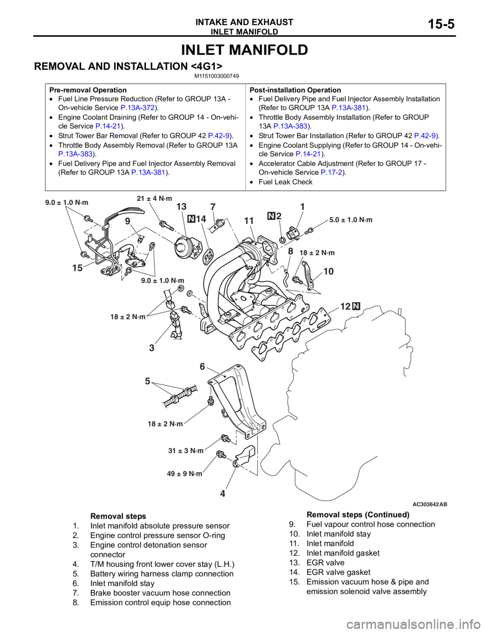
Removal steps
1.Inlet manifold absolute pressure sensor
2.Engine control pressure sensor O-ring
3.Engine control detonation sensor
connector
4.T/M housing front lower cover stay (L.H.)
5.Battery wiring harness clamp connection
6.Inlet manifold stay
7.Brake booster vacuum hose connection
8.Emission control equip hose connection
9.Fuel vapour control hose connection
10.Inlet manifold stay
11 .Inlet manifold
12.Inlet manifold gasket
13.EGR valve
14.EGR valve gasket
15.Emission vacuum hose & pipe and
emission solenoid valve assembly
Removal steps (Continued)
Page 56 of 800
INLET MANIFOLD
INTAKE AND EXHAUST15-6
REMOVAL AND INSTALLATION <4G6>
M1151003001236
Pre-removal Operation
•Fuel Line Pressure Reduction (Refer to GROUP 13A -
On-vehicle Service P.13B-325).
•Engine Coolant Draining (Refer to GROUP 14 - On-vehi-cle Service P.14-21).
•Strut Tower Bar Removal (Refer to GROUP 42 P.42-9).
•Throttle Body Assembly Re moval (Refer to GROUP 13B
P.13B-335).
•Fuel Delivery Pipe and Fuel Injector Assembly Removal
(Refer to GROUP 13B
P.13B-333).
Post-installation Operation
•Fuel Delivery Pipe and Fuel Injector Assembly Installation
(Refer to GROUP 13B P.13B-333).
•Throttle Body Assembly Inst allation (Refer to GROUP
13B P.13B-335).
•Strut Tower Bar Installati on (Refer to GROUP 42 P.42-9).
•Engine Coolant Supplying (Refer to GROUP 14 - On-vehi-
cle Service P.14-21).
•Accelerator Cable Adjustment (Refer to GROUP 17 -
On-vehicle Service
P.17-2).
•Fuel Leak Check
AC303657
9.0 ± 1.0 N·m11 ± 1 N·m
20 ± 2 N·m 31 ± 3 N·m
36 ± 6 N·m
20 ± 2 N·m
20 ± 2 N·m
36 ± 6 N·m
20 ± 2 N·m
11
9
10
2
12
N14
13N
AB
5.0 ± 1.0 N·m
3
1
11 ± 1 N·m
4
N
13 ± 1 N·m
5
6
(Engine oil)
7
8
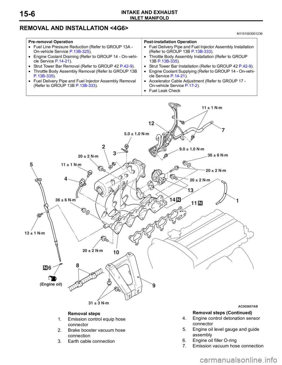
Removal steps
1.Emission control equip hose
connector
2.Brake booster vacuum hose
connection
3.Earth cable connection
4.Engine control detonation sensor
connector
5.Engine oil level gauge and guide
assembly
6.Engine oil filler O-ring
7.Emission vacuum hose connection
Removal steps (Continued)
Page 58 of 800
Removal steps
1.Front exhaust pipe connection
2.Exhaust pipe gasket
<>>>A<<3.Engine control oxygen sensor (front)
4.Engine oil level gauge and guide
assembly
5.Engine oil filler O-ring
6.Exhaust manifold cover
7.Exhaust manifold bracket
8.Exhaust manifold
9.Exhaust manifold gasket
EXHAUST MANIFOLD
INTAKE AND EXHAUST15-8
REMOVAL SERVICE POINT
<> ENGINE CONTROL OXYGEN SEN-
SOR (FRONT) REMOVAL
AC212566AC
MD998770
Engine control
oxygen sensor
(front)
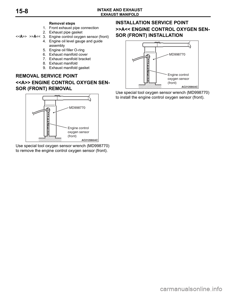
Use spe c ia l tool oxyg en sen s or wrench (MD9987 70)
to remove t
he eng ine contro l oxygen sen s or (fro nt).
INSTALLA T ION SER VICE POINT
>>A<< ENGINE CONT ROL OXYGEN SEN-
SOR (FRONT) INSTALLA TION
AC212566AC
MD998770
Engine control
oxygen sensor
(front)
Use spe c ia l tool oxyg en sen s or wrench (MD9987 70)
to inst
all the eng ine contro l oxyge n sen s or (f ront).