check engine MITSUBISHI MONTERO 1987 1.G User Guide
[x] Cancel search | Manufacturer: MITSUBISHI, Model Year: 1987, Model line: MONTERO, Model: MITSUBISHI MONTERO 1987 1.GPages: 284, PDF Size: 14.74 MB
Page 132 of 284
8-112 IGNITION SYSTEM - Service Adjustment Procedures
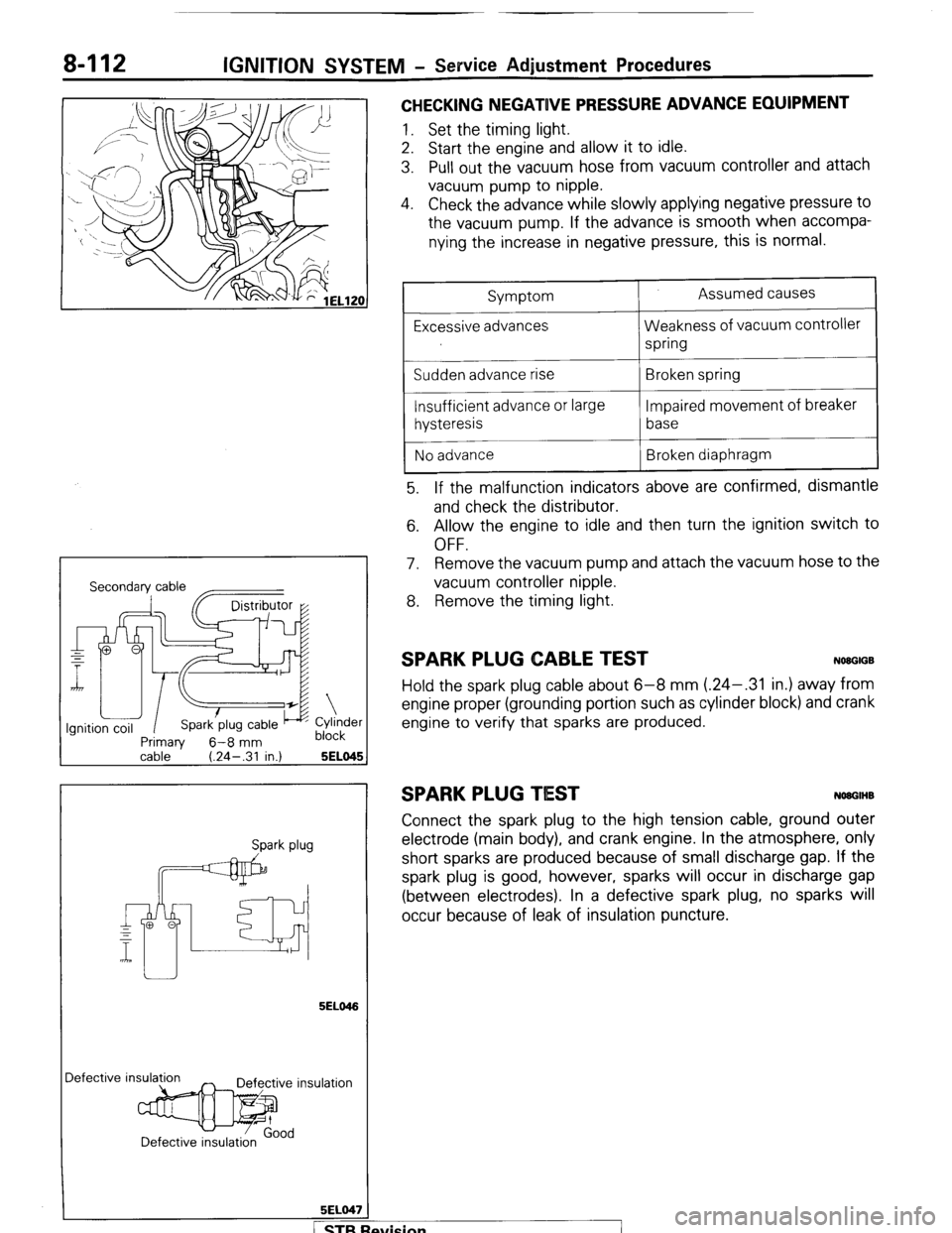
CHECKING NEGATIVE PRESSURE ADVANCE EQUIPMENT
1. Set the timing light.
2. Start the engine and allow it to idle.
3. Pull out the vacuum hose from vacuum controller and attach
vacuum pump to nipple.
4. Check the advance while slowly applying negative pressure to
the vacuum pump. If the advance is smooth when accompa-
nying the increase in negative pressure, this is normal.
Secondary cable
~~
Primaw 6-8 mm
Cylinder
block
cable ’ (.24-.31 in.) 5ELO45 1
Spark plug
5ELO46
Iefective insula
5ELO47
/
Symptom
Excessive advances
Sudden advance rise
Insufficient advance or large
hysteresis
No advance Assumed causes
Weakness of vacuum controller
spring
Broken spring
Impaired movement of breaker
base
Broken diaphragm
5. If the malfunction indicators above are confirmed, dismantle
and check the distributor.
6. Allow the engine to idle and then turn the ignition switch to
OFF.
7. Remove the vacuum pump and attach the vacuum hose to the
vacuum controller nipple.
8. Remove the timing light.
SPARK PLUG CABLE TEST NWGIGB
Hold the spark plug cable about 6-8 mm (.24-.31 in.) away from
engine proper (grounding portion such as cylinder block) and crank
engine to verify that sparks are produced.
SPARK PLUG TIEST NOUGIHB
Connect the spark plug to the high tension cable, ground outer
electrode (main body), and crank engine. In the atmosphere, only
short sparks are produced because of small discharge gap. If the
spark plug is good, however, sparks will occur in discharge gap
(between electrodes). In a defective spark plug, no sparks will
occur because of leak of insulation puncture.
fvision
I
Page 133 of 284
IGNITION SYSTEM-Service Adjustment Procedures 8-113
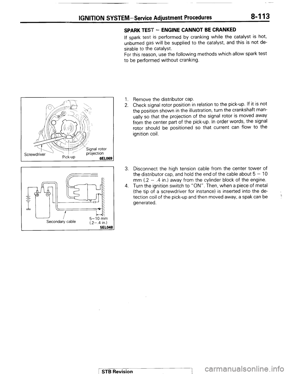
SPARK TEST - ENGINE CANNOT BE CRANKED
If spark test is performed by cranking while the catalyst is hot,
unburned gas will be supplied to the catalyst, and this is not de-
sirable to the catalyst.
For this reason, use the following methods which allow spark test
to be performed without cranking.
1. Remove the distributor cap.
2. Check signal rotor position in relation to the pick-up. If it is not
the position shown in the illustration, turn the crankshaft man-
ually so that the projection of the signal rotor is moved away
from the center part of the pick-up. In order words, the signal
rotor should be positioned so that current can flow to the
ignition coil.
3. Disconnect the high tension cable from the center tower of
the distributor cap, and hold the end of the cable about 5 - 10
mm (.2 - .4 in.) away from the cylinder block of the engine.
4. Turn the ignition switch to “ON”. Then, when a piece of metal
(the tip of a screwdriver for instance) is inserted into the de-
tection coil of the pick-up and then moved away, a spak can be
generated.
+
!:’
Secondary cable 5-10 km
(.2-.4 in.)
5EL0
1 STB Revision
Page 135 of 284
IGNITION SYSTEM - Ignition Svstem 8-115
Good No good
721017
72T06t
16W947
SERVICE POINTS OF REMOVAL
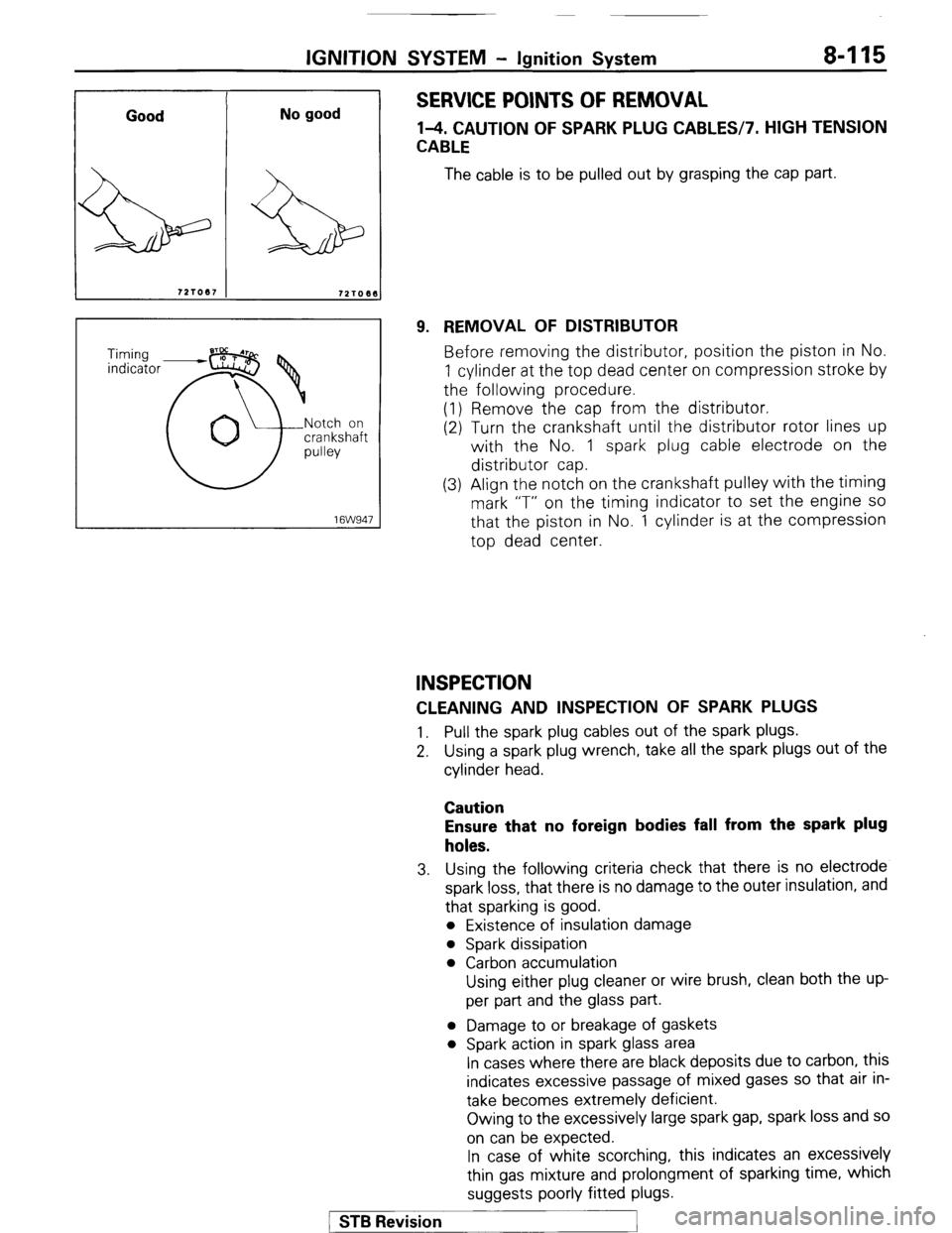
l-4. CAUTION OF SPARK PLUG CABLES17. HIGH TENSION
CABLE
The cable is to be pulled out by grasping the cap part.
9. REMOVAL OF DISTRIBUTOR
Before removing the distributor, position the piston in No.
1 cylinder at the top dead center on compression stroke by
the following procedure.
(1) Remove the cap from the distributor.
(2) Turn the crankshaft until the distributor rotor lines up
with the No. 1 spark plug cable electrode on the
distributor cap.
(3) Align the notch on the crankshaft pulley with the timing
mark “T” on the timing indicator to set the engine
SO
that the piston in No. 1 cylinder is at the compression
top dead center.
INSPECTION
CLEANING AND INSPECTION OF SPARK PLUGS
1. Pull the spark plug cables out of the spark plugs.
2. Using a spark plug wrench, take all the spark plugs out of the
cylinder head.
Caution
Ensure that no foreign bodies fall from the spark plug
holes.
3. Using the following criteria check that there is no electrode
spark loss, that there is no damage to the outer insulation, and
that sparking is good.
l Existence of insulation damage
l Spark dissipation
l Carbon accumulation
Using either plug cleaner or wire brush, clean both the up-
per part and the glass part.
l Damage to or breakage of gaskets
l Spark action in spark glass area
In cases where there are black deposits due to carbon, this
indicates excessive passage of mixed gases so that air in-
take becomes extremely deficient.
Owing to the excessively large spark gap, spark loss and so
on can be expected.
In case of white scorching, this indicates an excessively
thin gas mixture and prolongment of sparking time, which
suggests poorly fitted plugs.
/ STB Revision
1
Page 151 of 284
METERS AND GAUGES - Service Adiustment Procedures 8-131
r
(harness side) 16W834
Stopper (upper)
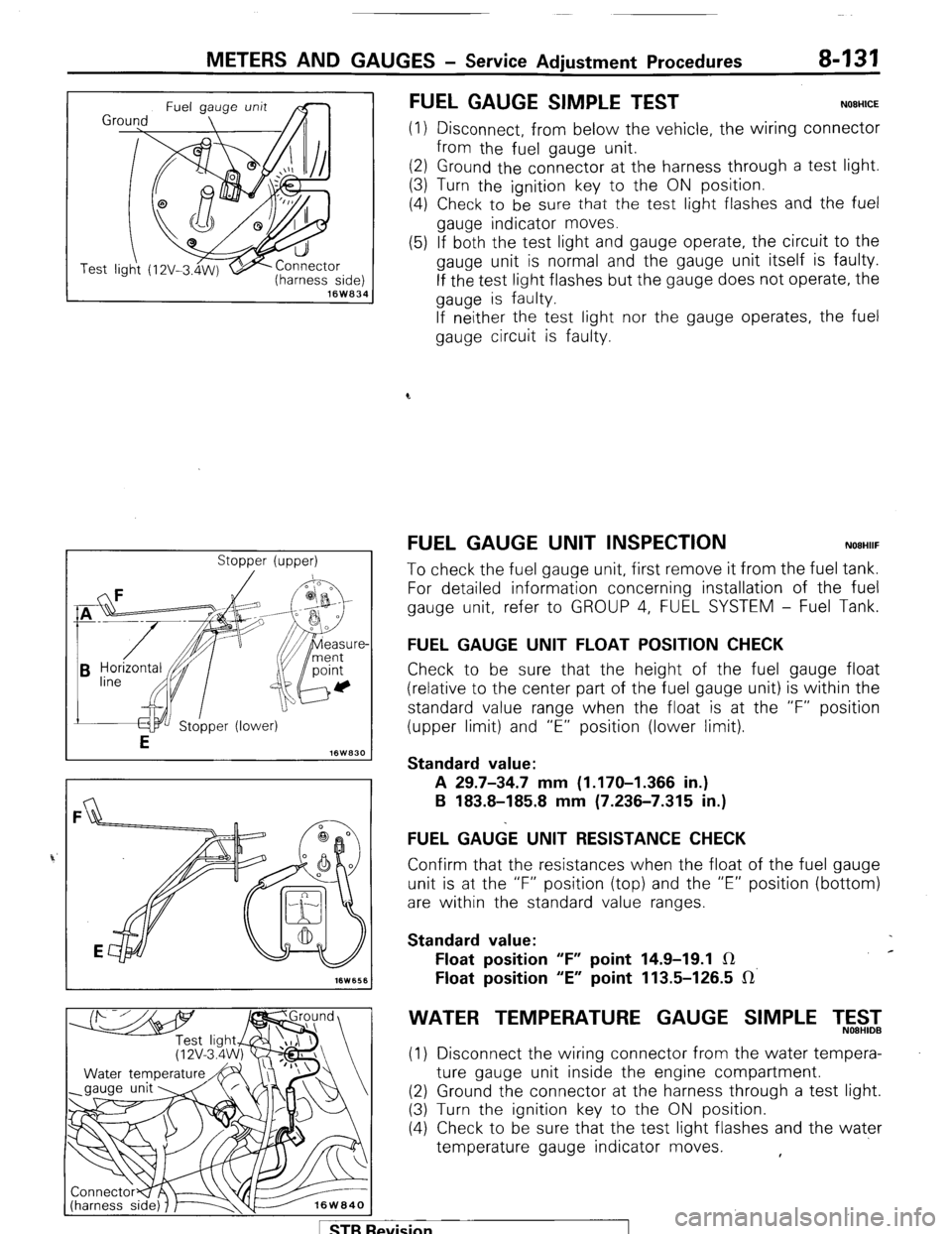
FUEL GAUGE SIMPLE TEST NOEHICE
(1) Disconnect, from below the vehicle, the wiring connector
from the fuel gauge unit.
(2) Ground the connector at the harness through a test light.
(3) Turn the ignition key to the ON position.
(4) Check to be
sure that the test light flashes and the fuel
gauge indicator moves.
(5) If both the test light and gauge operate, the circuit to the
gauge unit is normal and the gauge unit itself is faulty.
If the test light flashes but the gauge does not operate, the
gauge is faulty.
If neither the test light nor the gauge operates, the fuel
gauge circuit is faulty.
FUEL GAUGE UNIT INSPECTION NOEHIIF
To check the fuel gauge unit, first remove it from the fuel tank.
For detailed information concerning installation of the fuel
gauge unit, refer to GROUP 4, FUEL SYSTEM - Fuel Tank.
FUEL GAUGE UNIT FLOAT POSITION CHECK
Check to be sure that the height of the fuel gauge float
(relative to the center part of the fuel gauge unit) is within the
standard value range when the float is at the “F” position
(upper limit) and “E” position (lower limit).
Standard value:
A 29.7-34.7 mm (1.170-I .366 in.)
B 183.8-185.8 mm (7.236-7.315 in.)
FUEL GA&E UNIT RESISTANCE CHECK
Confirm that the resistances when the float of the fuel gauge
unit is at the “F” position (top) and the “E” position (bottom)
are within the standard value ranges.
Standard value:
Float position “F” point 14.9-19.1 IR c
Float position “E” point 113.5-126.5 IR’
WATER TEMPERATURE GAUGE SIMPLE T,5$2
(1) Disconnect the wiring connector from the water tempera-
ture gauge unit inside the engine compartment.
(2) Ground the connector at the harness through a test light.
(3) Turn the ignition key to the ON position.
(4) Check to be sure that the test light flashes and the water
temperature gauge indicator moves. ,
1 STB Revision
Page 152 of 284
8-132 METERS AND GAUGES - Service Adjustment Procedures
(5) If both the test light and gauge operate, the circuit to the
gauge unit is normal and the gauge unit itself is faulty.
If the test light flashes but the gauge does not operate, the
gauge is faulty.
If 1 neither the test light nor the gauge operates, the water
temperature gauge circuit is faulty.
Se
VVATER TEMPERATURE GAUGE UNIT ONSPEC-
TION
NOBHIKD
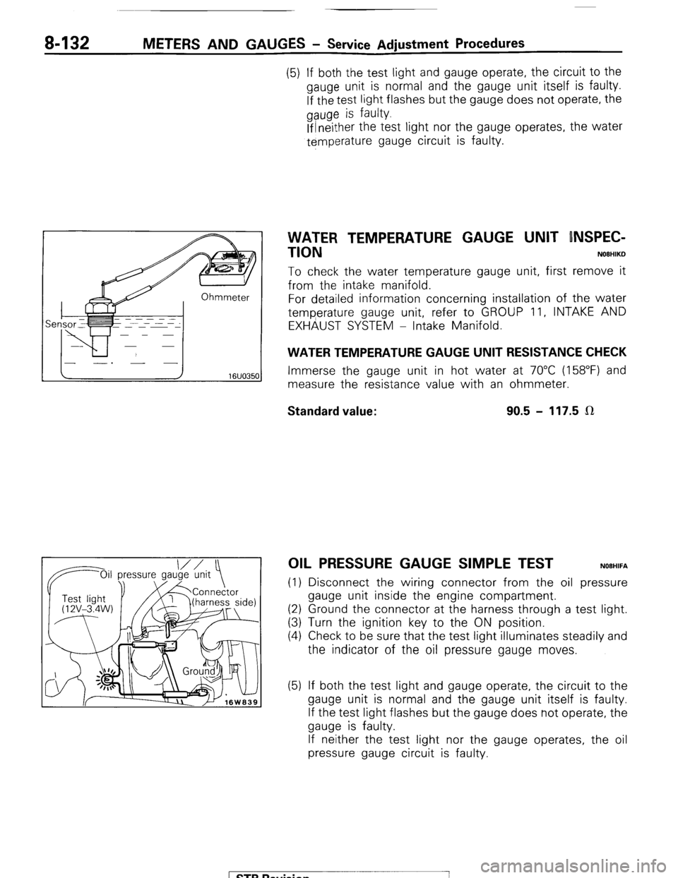
To check the water temperature gauge unit, first remove it
from the intake manifold.
For detailed information concerning installation of the water
temperature gauge unit, refer to GROUP 11, INTAKE AND
EXHAUST SYSTEM - Intake Manifold.
WATER TEMPERATURE GAUGE UNIT RESISTANCE CHECK
Immerse the gauge unit in hot water at 70°C (158°F) and
measure the resistance value with an ohmmeter.
Standard value: 90.5 - 117.5 LR
OIL PRESSURE GAUGE SIMPLE TEST NOEHIFA
(1) Disconnect the wiring connector from the oil pressure
gauge unit inside the engine compartment.
(2) Ground the connector at the harness through a test light.
(3) Turn the ignition key to the ON position.
(4) Check to be sure that the test light illuminates steadily and
the indicator of the oil pressure gauge moves.
(5) If both the test light and gauge operate, the circuit to the
gauge unit is normal and the gauge unit itself is faulty.
If the test light flashes but the gauge does not operate, the
gauge is faulty.
If neither the test light nor the gauge operates, the oil
pressure gauge circuit is faulty.
1 STB Revision
-7
Page 153 of 284
METERS AND GAUGES - Service Adjustment Procedures 8-133
IOil p Oil pressure ressure
gauge unit
1 I Test light
‘@‘(12V - 3.4 I
W)
16W1576
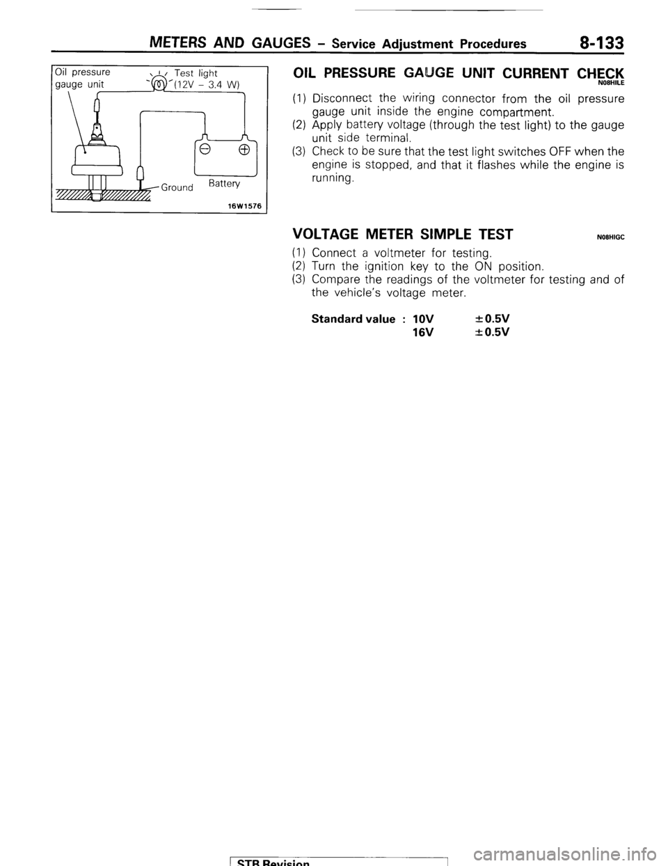
OIL PRESSURE GA GE UNIT CURRENT CHEC,‘l<,
(1) Disconnect the wiring connector from the oil pressure
gauge unit inside the engine compartment.
(2) Apply battery voltage (through the test light) to the gauge
unit side terminal.
(3) Check to be sure that the test light switches OFF when the
engine is stopped, and that it flashes while the engine is
running.
VOLTAGE METER SIMPLE TEST NOEHIGC
(1) Connect a voltmeter for testing.
(2) Turn the ignition key to the ON position.
(3) Compare the readings of the voltmeter for testing and of
the vehicle’s voltage meter. Standard value : 1OV
16V + 0.5v
+ 0.5v
1 STB Revision
Page 161 of 284
METERS AND GAUGES - Indicators and Warning Lights 8-141
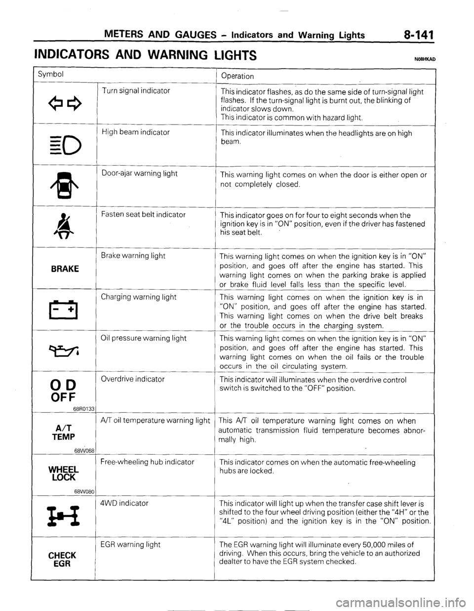
INDICATORS AND WARNING
LIGHTS
Symbol
Operation
Turn signal indicator
+e3 This indicator flashes, as do the same side of turn-signal light
flashes. If the turn-signal light is burnt out, the blinking of
indicator slows down.
This indicator is common with hazard light.
0
High beam indicator
- This indicator illuminates when the headlights are on high
= beam.
=
* Door-ajar warning light
This warning light comes on when the door is either open or
not completely closed.
4 Fasten seat belt indicator
This indicator goes on for four to eight seconds when the
ignition key is in “ON” position, even if the driver has fastened
his seat belt.
BRAKE
Brake warning light
This warning light comes on when the ignition key is in “ON”
position, and goes off after the engine has started. This
warning light comes on when the parking brake is applied
or brake fluid level falls less than the specific level.
III Charging warning light This warning light comes on when the ignition key is in
- + “ON” position, and goes off after the engine has started.
This warning light comes on when the drive belt breaks
or the trouble occurs in the charging system.
Oil pressure warning light This warning light comes on when the ignition key is in “ON”
P position, and goes off after the engine has started. This
warning light comes on when the oil fails or the trouble
occurs in the oil circulating system.
00
Overdrive indicator
This indicator will illuminates when the overdrive control
OFF
switch is switched to the “OFF” position.
68R0133
A/T
A/T oil temperature warning light This A/T oil temperature warning light comes on when
TEMP automatic transmission fluid temperature becomes abnor-
mally high.
68WO68
Free-wheeling hub indicator
YEL This indicator comes on when the automatic free-wheeling
hubs are locked.
68WO80
z4 4WD indicator This indicator will light up when the transfer case shift lever is
shifted to the four wheel driving position (either the “4H” or the
“4L” position) and the ignition key is in the “ON” position.
CHECK
EGR
EGR warning light The EGR warning light will illuminate every 50,000 miles of
driving. When this occurs, bring the vehicle to an authorized
dealter to have the EGR system checked.
) STB Revision
Page 162 of 284
8-142 METERS AND GAUGES - EGR Warning System
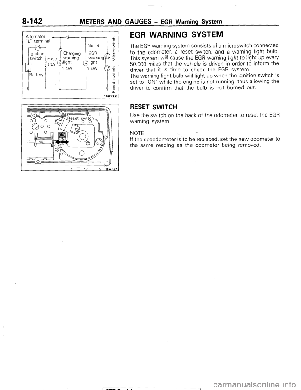
EGR WARNING SYSTEM
The EGR warning system consists of a microswitch connected
to the odometer, a reset switch, and a warning light bulb.
This system will cause the EGR warning light to light up every
50,000 miles that the vehicle is driven in order to inform the
driver that it is time to check the EGR system.
The warning light bulb will light up when the ignition switch is
set to “ON” while the engine is not running, thus allowing the
driver to confirm that the bulb is not burned out.
RESET SWITCH
Use the switch on the back of the odometer to reset the EGR
warning system.
NOTE
If the speedometer is to be replaced, set the new odometer to
the same reading as the odometer being, removed.
1 STB Revision
Page 260 of 284
AIR-CONDITIONING-Service Adjustment Procedures
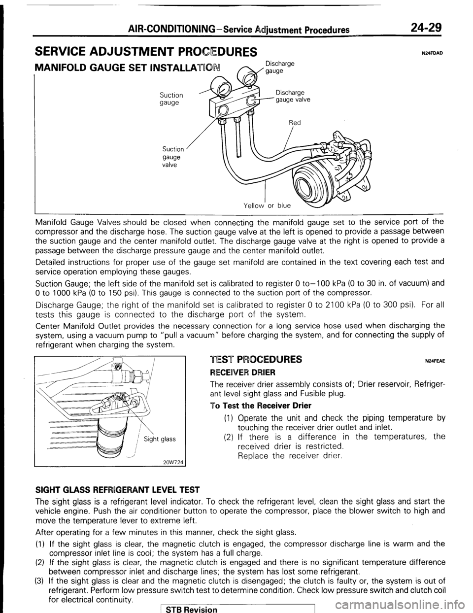
SERVICE ADJUSTMENT PROCQDURES 24-29 N24FDAD
MANIFOLD GAUGE SET INSTALLATUON Discharge
W gauge
Suction
gauge
Suction
gauge
valve Manifold Gauge Valves should be closed
when connecting the manifold gauge set to the service port of the
compressor and the discharge hose. The suction gauge valve at the left is opened to provide a passage between
the suction gauge and the center manifold outlet. The discharge gauge valve at the right is opened to provide a
passage between the discharge pressure gauge and the center manifold outlet.
Detailed instructions for proper use of the gauge set manifold are contained in the text covering each test and
service operation employing these gauges.
Suction Gauge; the left side of the manifold set is calibrated to register 0 to-100 kPa (0 to 30 in. of vacuum) and
0 to 1000 kPa (0 to 150 psi). This gauge is connected to the suction port of the compressor.
Discharge Gauge; the right of the manifold set is calibrated to register 0 to 2100 kPa (0 to 300 psi). For all
tests this gauge is connected to the discharge port of the system.
Center Manifold Outlet provides the necessary connection for a long service hose used when discharging the
system, using a vacuum pump to “pull a vacuum” before charging the system, and for connecting the supply of
refrigerant when charging the system
glass -
2OW724 N24FEAE The receiver drier assembly consists of; Drier reservoir, Refriger-
ant level sight glass and Fusible plug.
To Test the Receiver Drier (1) Operate the unit and check the piping temperature by
touching the receiver drier outlet and inlet.
(2) If there is a difference in the temperatures, the
received drier is restricted.
Replace the receiver drier.
SIGHT GLASS REFRlGERANT LEVEL TEST The sight glass is a refrigerant level indicator. To check the refrigerant level, clean the sight glass and start the
vehicle engine. Push the air conditioner button to operate the compressor, place the blower switch to high and
move the temperature lever to extreme left.
After operating for a few minutes in this manner, check the sight glass.
(1) If the sight glass is clear, the magnetic clutch is engaged, the compressor discharge line is warm and the
compressor inlet line is cool; the system has a full charge.
(2) If the sight glass is clear, the magnetic clutch is engaged and there is no significant temperature difference
between compressor inlet and discharge lines; the system has lost some refrigerant.
(3) If the sight glass is clear and the magnetic clutch is disengaged; the clutch is faulty or, the system is out of
refrigerant. Perform low pressure switch test to determine condition. Check low pressure switch and clutch coil
for electrical continuity.
1 STB Revision
Page 265 of 284
AIR-CONDITIONING-Service Adjustment Procedures
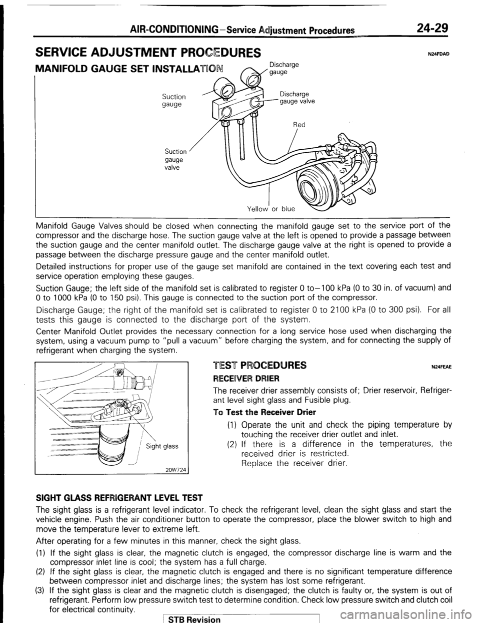
SERVICE ADJUSTMENT PROCQDURES 24-29 N24FDAD
MANIFOLD GAUGE SET INSTALLATUON Discharge
W gauge
Suction
gauge
Suction
gauge
valve Manifold Gauge Valves should be closed
when connecting the manifold gauge set to the service port of the
compressor and the discharge hose. The suction gauge valve at the left is opened to provide a passage between
the suction gauge and the center manifold outlet. The discharge gauge valve at the right is opened to provide a
passage between the discharge pressure gauge and the center manifold outlet.
Detailed instructions for proper use of the gauge set manifold are contained in the text covering each test and
service operation employing these gauges.
Suction Gauge; the left side of the manifold set is calibrated to register 0 to-100 kPa (0 to 30 in. of vacuum) and
0 to 1000 kPa (0 to 150 psi). This gauge is connected to the suction port of the compressor.
Discharge Gauge; the right of the manifold set is calibrated to register 0 to 2100 kPa (0 to 300 psi). For all
tests this gauge is connected to the discharge port of the system.
Center Manifold Outlet provides the necessary connection for a long service hose used when discharging the
system, using a vacuum pump to “pull a vacuum” before charging the system, and for connecting the supply of
refrigerant when charging the system
glass -
2OW724 N24FEAE The receiver drier assembly consists of; Drier reservoir, Refriger-
ant level sight glass and Fusible plug.
To Test the Receiver Drier (1) Operate the unit and check the piping temperature by
touching the receiver drier outlet and inlet.
(2) If there is a difference in the temperatures, the
received drier is restricted.
Replace the receiver drier.
SIGHT GLASS REFRlGERANT LEVEL TEST The sight glass is a refrigerant level indicator. To check the refrigerant level, clean the sight glass and start the
vehicle engine. Push the air conditioner button to operate the compressor, place the blower switch to high and
move the temperature lever to extreme left.
After operating for a few minutes in this manner, check the sight glass.
(1) If the sight glass is clear, the magnetic clutch is engaged, the compressor discharge line is warm and the
compressor inlet line is cool; the system has a full charge.
(2) If the sight glass is clear, the magnetic clutch is engaged and there is no significant temperature difference
between compressor inlet and discharge lines; the system has lost some refrigerant.
(3) If the sight glass is clear and the magnetic clutch is disengaged; the clutch is faulty or, the system is out of
refrigerant. Perform low pressure switch test to determine condition. Check low pressure switch and clutch coil
for electrical continuity.
1 STB Revision