MITSUBISHI MONTERO 2000 Service Owner's Guide
Manufacturer: MITSUBISHI, Model Year: 2000, Model line: MONTERO, Model: MITSUBISHI MONTERO 2000Pages: 1839, PDF Size: 29.19 MB
Page 31 of 1839

Page 32 of 1839

Page 33 of 1839

GENERAL -Precautions Before Service00-32
Other precautions:
DAvoid prolonged and repeated contact with oils,
particularly used engine oils.
DWear protective clothing, including impervious gloves
where practicable.
DAvoid contaminating clothes, particularly underpants, with
oil.
DDo not put oily rags in pockets, the use of overalls without
pockets will avoid this.
DDo not wear heavily soiled clothing and oil-impregnated
foot-wear. Overalls must be cleaned regularly and kept
separately from personal clothing.
DWhere there is a risk of eye contact, eye protection should
be worn, for example, chemical goggles or face shields;
in addition an eye wash facility should be provided.
DObtain First Aid treatment immediately for open cuts and
wounds.
DWash regularly with soap and water to ensure all oil is
removed, especially before meals (skin cleansers and
nail brushes will help). After cleaning, the application of
preparations containing lanolin to replace the natural skin
oils is advised.
DDo not use petrol, kerosine, diesel fuel, gas oil, thinners
or solvents for cleaning skin.
DUse barrier creams, applying them before each work
period, to help the removal of oil from the skin after work.
DIf skin disorders develop, obtain medical advice without
delay.
www.WorkshopManuals.co.uk
Purchased from www.WorkshopManuals.co.uk
Page 34 of 1839

S
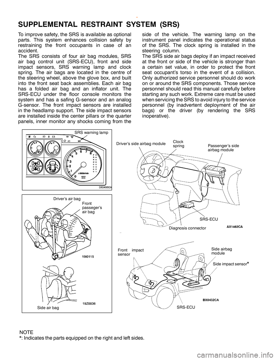
U PPLE M EN TA L RESTR AIN T SYSTE M (S R S)
T o im pro ve sa fe ty , th e SR S is ava ila ble as optio nal
p arts . This syste m enhance s co llis io n sa fe ty by
r e str a in in g th e fr o nt occu pants in ca se of an
a ccid ent.
T he SR S co nsis ts of fo ur air bag module s, SR S
a ir bag co ntr o l unit (S R S-E C U), fr o nt and sid e
i m pact se nso rs , SR S warn in g la m p and clo ck
s p rin g. The air bags are lo ca te d in th e ce ntr e of
t h e ste erin g wheel, above th e glo ve box, and built
i n to th e fr o nt se at back asse m blie s. E ach air bag
h as a fo ld ed air bag and an in fla to r unit . The
S R S-E C U under th e flo or co nso le monit o rs th e
s yste m and has a sa fin g G-s e nso r and an analo g
G -s e nso r. The fr o nt im pact se nso rs are in sta lle d
i n th e headla m p su pport. T he sid e im pact se nso rs
a re in sta lle d in sid e th e ce nte r pilla rs or th e quarte r
p anels , in ner m onit o r any sh ocks co m in g fr o m th e s
id e of th e ve hic le . The warn in g la m p on th e
i n str u m ent panel in dic a te s th e opera tio nal sta tu s
o f th e SR S. The clo ck sp rin g is in sta lle d in th e
s te erin g co lu m n.
T he SR S sid e air bags deplo y if a n im pact re ce iv e d
a t th e fr o nt or sid e of th e ve hic le is str o nger th an
a ce rta in se t va lu e, in ord er to pro te ct th e fr o nt
s e at occu pant’s to rs o in th e eve nt of a co llis io n.
O nly auth oriz e d se rv ic e pers o nnelsh ould do work
o n or aro und th e SR S co m ponents . T hose se rv ic e
p ers o nnelsh ould re ad th is m anualca re fu lly befo re
s ta rtin g any su ch work . E xtr e m eca re m ust b e use d
w hen se rv ic in g th e SR S to avo id in ju ry to th e se rv ic e
p ers o nnel (b y in adve rte nt deplo ym ent of th e air
b ags) or th e driv e r (b y re nderin g th e SR S
i n opera tiv e ). F
ro nt
p asse ger’s
a ir bag
N O TE
* : In dic a te s th e parts equip ped on th e rig hta nd le ft sid es. S
R S-E C U D
ia gnosis co nnecto r D
riv e r’s sid e air b ag m odule P
asse nger’s sid e
a ir b ag m odule C
lo ck
s p rin g S
id e air b ag
m odule S
id e im pacts e nso r
* F
ro nt im pact
s e nso r
Page 35 of 1839

S
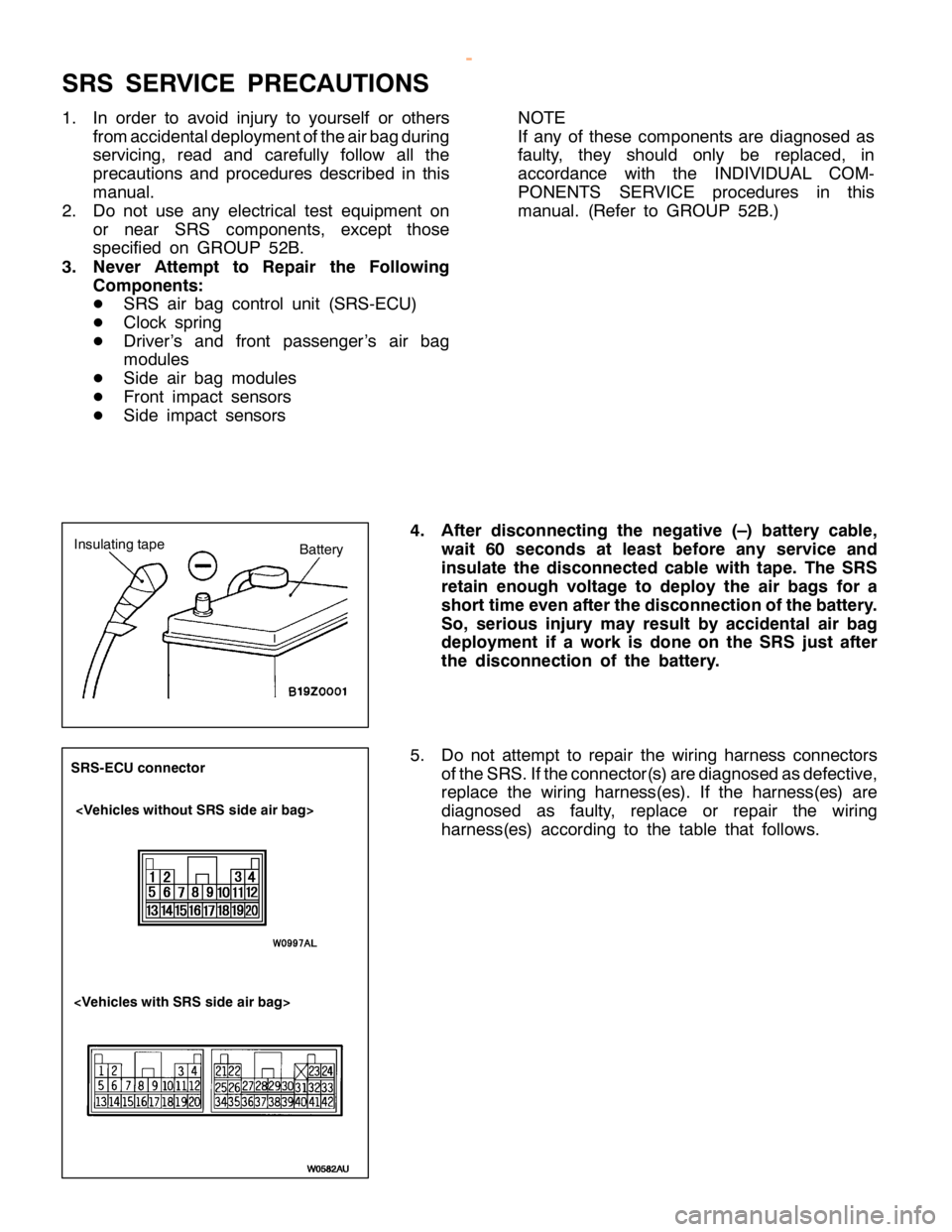
R S SER VIC E PR EC AUTIO NS
1 . In ord er to avo id in ju ry to yo urs e lf or oth ers
f r o m accid enta ld eplo ym ento fth e air b ag durin g
s e rv ic in g, re ad and ca re fu lly fo llo w all th e
p re ca utio ns and pro ce dure s describ ed in th is
m anual.
2 . Do not use any ele ctr ic a l te st equip m ent on
o r near SR S co m ponents , exce pt th ose
s p ecif ie d on GRO UP 52B .
3 . Never Atte m pt to Rep air th e Follo w in g
C om ponen ts :
D SR S air bag co ntr o l unit (S R S-E C U)
D Clo ck sp rin g
D Driv e r’s and fr o nt passe nger’s air bag
m odule s
D Sid e air bag module s
D Fro nt im pact se nso rs
D Sid e im pact se nso rs N
O TE
I f any of th ese co m ponents are dia gnose d as
f a ult y , th ey sh ould only be re pla ce d, in
a cco rd ance wit h th e IN DIV ID UAL CO M -
P O NEN TS SER VIC E pro ce dure s in th is
m anual. (R efe r to GRO UP 52B .)
4 . Afte r dis co nnectin g th e neg ativ e (– ) batte ry cab le ,
w ait 60 seco nds at le ast befo re an y serv ic e an d
i n su la te th e dis co nnecte d cab le wit h ta p e. The SR S
r e ta in en ough vo lt a g e to dep lo y th e air bag s fo r a
s h ort tim eeven afte r th e dis co nnectio n ofth e batte ry .
S o, serio us in ju ry may re su lt by accid en ta l air bag
d ep lo ym en t if a work is done on th e SR S ju st afte r
t h e dis co nnectio n of th e batte ry .
5 . Do not atte m pt to re pair th e wir in g harn ess co nnecto rs
o fth e SR S.If th e co nnecto r(s ) a re dia gnose d as defe ctiv e ,
r e pla ce th e wir in g harn ess(e s). If th e harn ess(e s) are
d ia gnose d as fa ult y , re pla ce or re pair th e wir in g
h arn ess(e s) acco rd in g to th e ta ble th at fo llo w s. S
R S-E C U co nnecto r <
V eh ic le s wit h SR S sid e air bag >
w
ww.W ork sh opM an uals .c o .u k
P urc h ased f r o m w ww.W ork sh opM an uals .c o .u k
Page 36 of 1839

GENERAL -Supplemental Restraint System (SRS)00-35
SRS-ECU
Terminal No.Destination of harnessCorrective action
1, 2, 3, 4Instrument panel wiring harness®Front wiring harness®Front
impact sensorRepair or replace each wiring
harness
7Instrument panel wiring harness®EarthRepair or replace Instrument
8Instrument panel wiring harness®Combination meter
(SRS warning lamp)
panel wiring harness
9, 10Instrument panel wiring harness®Front passenger’s air bag
module
11 , 1 2Instrument panel wiring harness®Clock spring®Driver’s air bag
module)Repair or replace the Instrument
panel wiring harness. Replace
clock spring.
13Instrument panel wiring harness®Junction block (fuse No.8)Repair or replace Instrument
16Instrument panel wiring harness®Junction block (fuse No.6)
panel wiring harness.
20Instrument panel wiring harness®Diagnosis connector
21, 22Side air bag wiring harness®Side air bag module (L.H.)Repair or replace side air bag
23, 24Side air bag wiring harness®Side air bag module (R.H.)
wiring harness.
34, 35, 36Side air bag wiring harness®Floor wiring harness®Side impact
sensor (L.H.)Repair or each wiring harness.
40, 41, 42Side air bag wiring harness®Floor wiring harness®Side impact
sensor (R.H.)
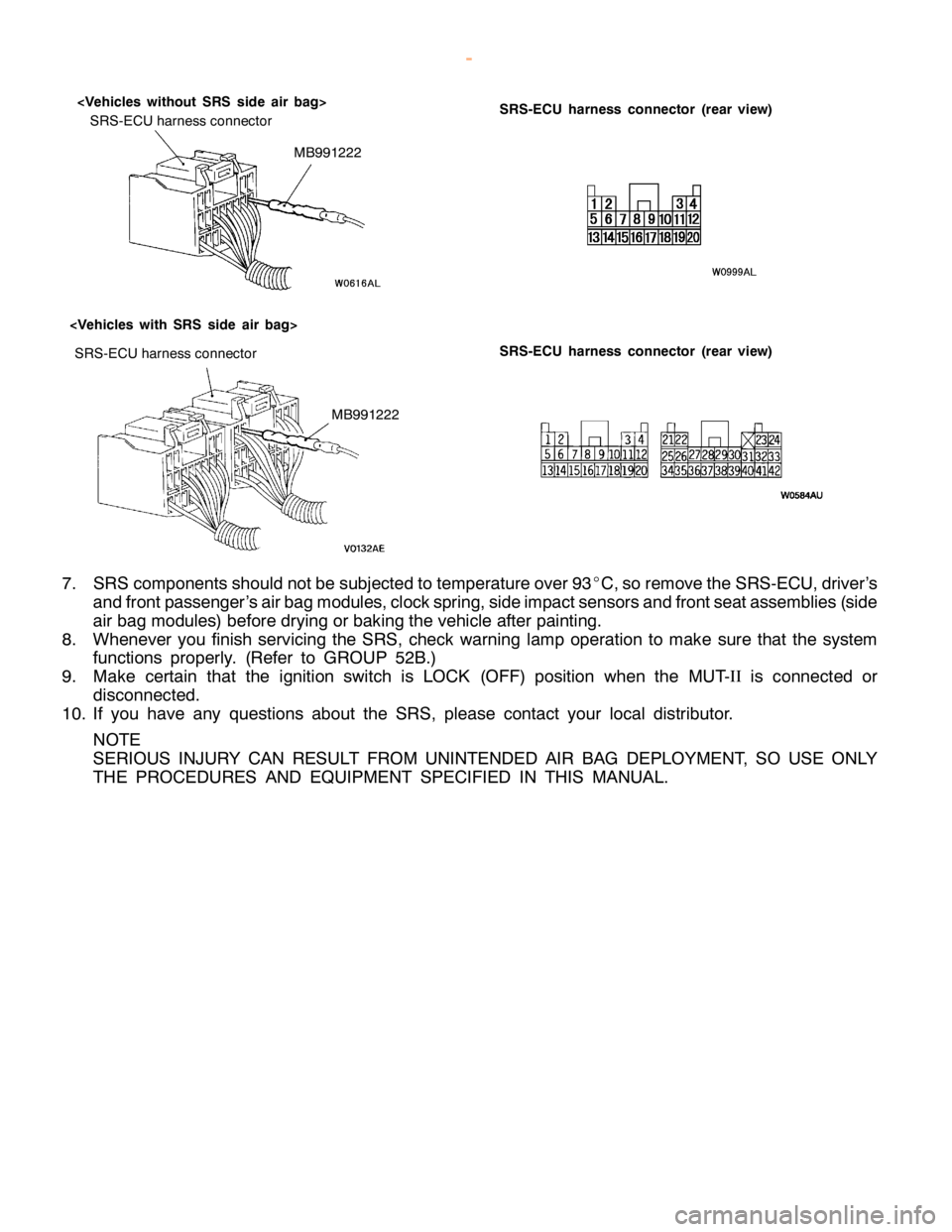
6. Inspection of the SRS-ECU harness connector should be carried out by the following procedure.
Insert the special tool (probe, MB991222, in the harness set) into the connector from harness side
(rear side), and connect the tester to this probe. If any tool than specified is used, damage to the
harness and other components will result. Furthermore, measurement should not be carried out by
touching the probe directly against the terminals from the front of the connector. The terminals are
plated to increase their conductivity, so that if they are touched directly by the probe, the plating
may break, which will cause drops in reliability.
www.WorkshopManuals.co.uk
Purchased from www.WorkshopManuals.co.uk
Page 37 of 1839

S
R S-E C U harn ess co nnecto r S
R S-E C U harn ess co nnecto r (r e ar vie w )
< V eh ic le s wit h SR S sid e air bag >
<
V eh ic le s wit h out SR S sid e air bag >
SR S-E C U harn ess co nnecto r (r e ar vie w ) M
B991222
7 . SR S co m ponents sh ould notb e su bje cte d to te m pera tu re ove r 93 _
C ,so re m ove th e SR S-E C U,d riv e r’s
a nd fr o ntp asse nger’s air b ag m odule s,c lo ck sp rin g,sid e im pact se nso rs and fr o nts e ata sse m blie s (s id e
a ir bag module s) befo re dry in g or bakin g th e ve hic le afte r pain tin g.
8 . Wheneve r yo u fin is h se rv ic in g th e SR S,ch eck warn in g la m p opera tio n to make su re th at th e syste m
f u nctio ns pro perly . (R efe r to GRO UP 52B .)
9 . Make ce rta in th at th e ig nit io n sw it c h is LO CK (O FF) posit io n when th e MUT-I
I
is co nnecte d or
d is co nnecte d.
1 0. If yo u have any questio ns about th e SR S, ple ase co nta ct yo ur lo ca l dis tr ib uto r.
N O TE
S ER IO US IN JU RY CAN RESU LT FR O M UNIN TE N DED AIR BAG DEPLO YM EN T, SO USE ONLY
T H E PR O CED URES AN D EQ UIP M EN T SPEC IF IE D IN TH IS MAN UAL.
w
ww.W ork sh opM an uals .c o .u k
P urc h ased f r o m w ww.W ork sh opM an uals .c o .u k
Page 38 of 1839

S
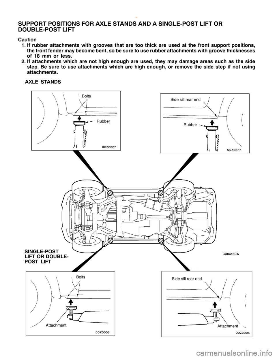
U PPO RT LO CATIO NS FO R LIF TIN G AND JA CKIN G
C au tio n
D o not su pport th e veh ic le s at lo catio ns oth er th an sp ecif ie d su pportin g poin ts . If do so , th is
w ill cau se dam ag e, etc .
S U PPO RT PO SIT IO NS FO R AGARAG E JA CK
C au tio n
N ever su pport an y poin t oth er th an th e sp ecif ie d one, or it will be defo rm ed .
Page 39 of 1839

S
id e sill re ar end S
IN G LE -P O ST
L IF T OR DO UBLE -
P O ST LIF T R
ubber B
olt s B
olt s A
tta ch m ent A
tta ch m ent
w
ww.W ork sh opM an uals .c o .u k
P urc h ased f r o m w ww.W ork sh opM an uals .c o .u k
Page 40 of 1839

GENERAL -Standard Part/Tightening-Torque Table00-39
STANDARD PART/TIGHTENING-TORQUE TABLE
Each torque value in the table is a standard value
for tightening under the following conditions.
(1) Bolts, nuts and washers are all made of steel
and plated with zinc.
(2) The threads and bearing surface of bolts and
nuts are all in dry condition.The values in the table are not applicable:
(1) If toothed washers are inserted.
(2) If plastic parts are fastened.
(3) If bolts are tightened to plastic or die-cast
inserted nuts.
(4) If self-tapping screws or self-locking nuts are
used.
Standard bolt and nut tightening torque
Thread sizeTorque N×
m
Bolt nominal
diameter (mm)Pitch (mm)Head mark “4”Head mark “7”Head mark “8”
M50.82.5±
0.55.0±
1.06.0±
1.0
M61.05.0±
1.09.0±
2.010±
2
M81.2512±
222±
425±
4
M101.2524±
444±
1053±
7
M121.2541±
883±
1298±
12
M141.573±
12140±
20155±
25
M161.511 0±
20210±
30235±
35
M181.5165±
25300±
40340±
50
M201.5225±
35410±
60480±
70
M221.5300±
40555±
85645±
95
M241.5395±
55735±
105855±
125
Flange bolt and nut tightening torque
Thread sizeTorque N×
m
Bolt nominal
diameter (mm)Pitch (mm)Head mark “4”Head mark “7”Head mark “8”
M61.05.0±
1.010±
212±
2
M81.2513±
224±
427±
5
M101.2526±
449±
958±
7
M101.524±
445±
855±
10
M121.2546±
895±
15105±
15
M121.7543±
883±
1298±
12
NOTE
1. Be sure to use only the specified bolts and nuts, and always tighten them to the specified torques.
2. Bolts marked with indications such as 4T or 7T are reinforced bolts. The larger the number, the
greater the bolt strength.
www.WorkshopManuals.co.uk
Purchased from www.WorkshopManuals.co.uk