MITSUBISHI MONTERO 2000 Service User Guide
Manufacturer: MITSUBISHI, Model Year: 2000, Model line: MONTERO, Model: MITSUBISHI MONTERO 2000Pages: 1839, PDF Size: 29.19 MB
Page 11 of 1839

GENERAL -How to Use Troubleshooting/Inspection Service Points00-10
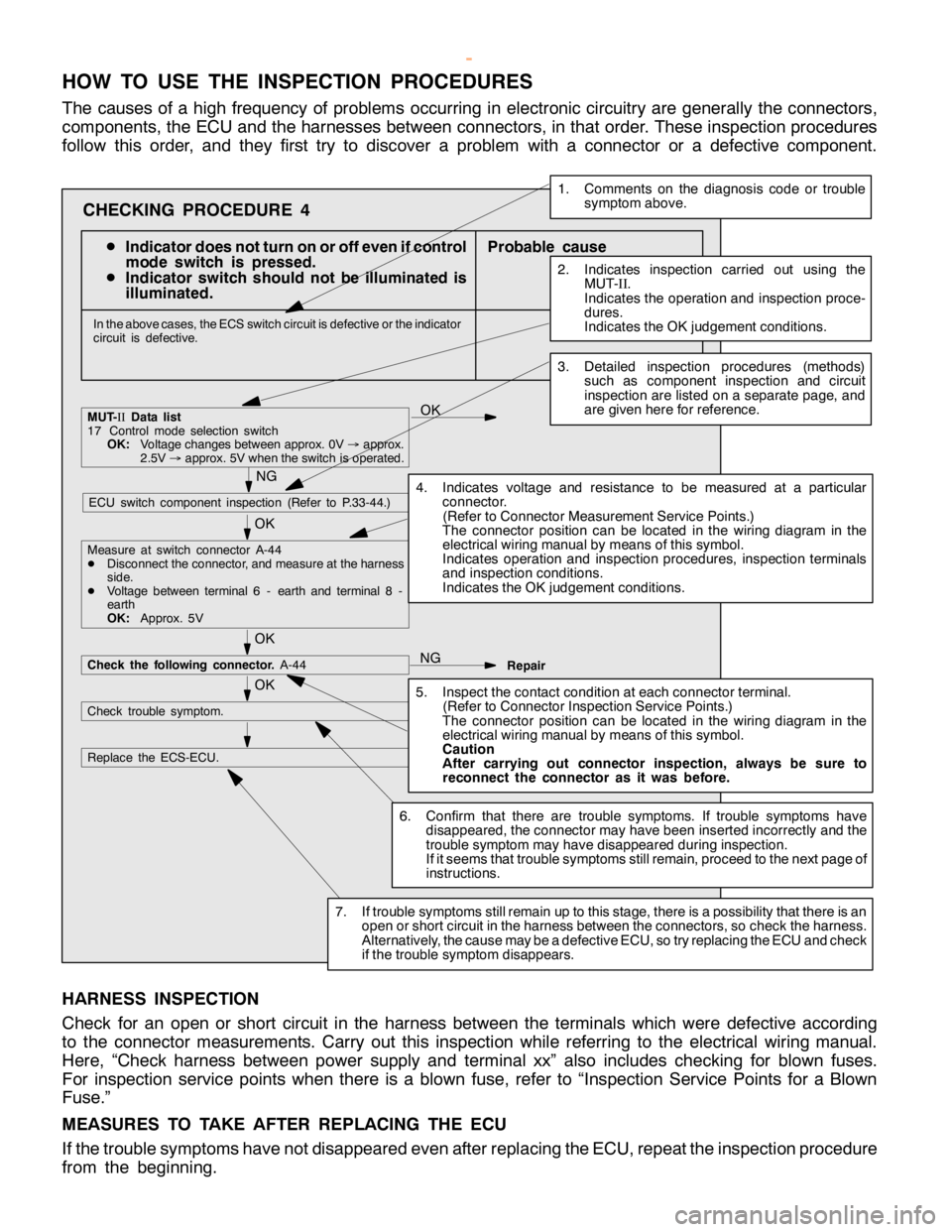
HOW TO USE THE INSPECTION PROCEDURES
The causes of a high frequency of problems occurring in electronic circuitry are generally the connectors,
components, the ECU and the harnesses between connectors, in that order. These inspection procedures
follow this order, and they first try to discover a problem with a connector or a defective component.
D
Indicator does not turn on or off even if control
mode switch is pressed.
D
Indicator switch should not be illuminated is
illuminated.Probable cause
OK
OK
OK
Measure at switch connector A-44
DDisconnect the connector, and measure at the harness
side.
DVoltage between terminal 6 - earth and terminal 8 -
earth
OK:Approx. 5V
OK
NG
Check the following connector.A-44
Repair
OK
Check trouble symptom.
Replace the ECS-ECU.
In the above cases, the ECS switch circuit is defective or the indicator
circuit is defective.
CHECKING PROCEDURE 4
2. Indicates inspection carried out using the
MUT-
II.
Indicates the operation and inspection proce-
dures.
Indicates the OK judgement conditions.
3. Detailed inspection procedures (methods)
such as component inspection andcircuit
inspection are listed on a separate page, and
are given here for reference.
5. Inspect the contact condition at each connectorterminal.
(Refer to Connector Inspection Service Points.)
The connector position can be located in the wiring diagram in the
electrical wiring manual bymeans ofthis symbol.
Caution
After carrying out connector inspection, always be sure to
reconnect the connector as it was before.
6. Confirm that there are trouble symptoms. If trouble symptomshave
disappeared, the connector may have been inserted incorrectly and the
trouble symptom mayhave disappeared during inspection.
If it seemsthat trouble symptoms still remain, proceed to the nextpage of
instructions.
7. If trouble symptoms still remain up to this stage, there is a possibility that there is an
open orshort circuit in the harness between the connectors, socheck the harness.
Alternatively, the cause may be a defectiveECU, so try replacing the ECU andcheck
if the trouble symptom disappears.
NGECU switch component inspection (Refer to P.33-44.)
NG
1. Comments on the diagnosis code ortrouble
symptom above.
MUT-II
Data list
17 Control mode selectionswitch
OK:Voltage changes between approx. 0V
®approx.
2.5V
®approx. 5V when the switch is operated.
4. Indicates voltage and resistance to be measured at a particular
connector.
(Refer to Connector Measurement Service Points.)
The connector position can be located in the wiring diagram in the
electrical wiring manual bymeans ofthis symbol.
Indicates operation and inspection procedures, inspection terminals
and inspection conditions.
Indicates the OK judgement conditions.
HARNESS INSPECTION
Check for an open or short circuit in the harness between the terminals which were defective according
to the connector measurements. Carry out this inspection while referring to the electrical wiring manual.
Here, “Check harness between power supply and terminal xx” also includes checking for blown fuses.
For inspection service points when there is a blown fuse, refer to “Inspection Service Points for a Blown
Fuse.”
MEASURES TO TAKE AFTER REPLACING THE ECU
If the trouble symptoms have not disappeared even after replacing the ECU, repeat the inspection procedure
from the beginning.
www.WorkshopManuals.co.uk
Purchased from www.WorkshopManuals.co.uk
Page 12 of 1839

E
xtr a -th in pro be
T e st bar
C onnecto r I
n sp ectio n harn ess
f o r co nnecto r pin
c o nta ct p re ssu re
Page 13 of 1839

M
B991219
Page 14 of 1839

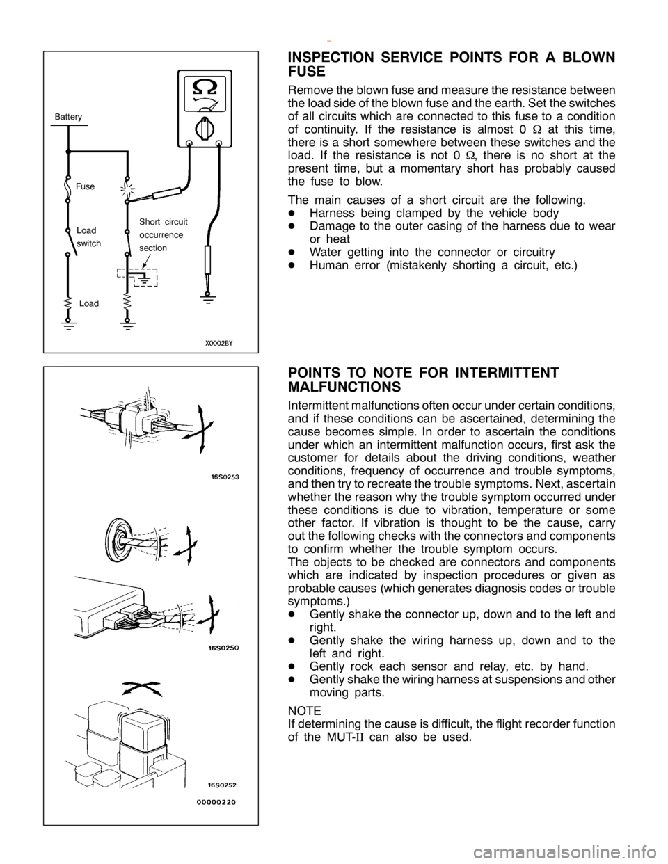
B
atte ry
L o ad
s w it c h L
o ad S
ho rt cir c u it
o ccu rre n ce
s e ctio n
Page 15 of 1839

T
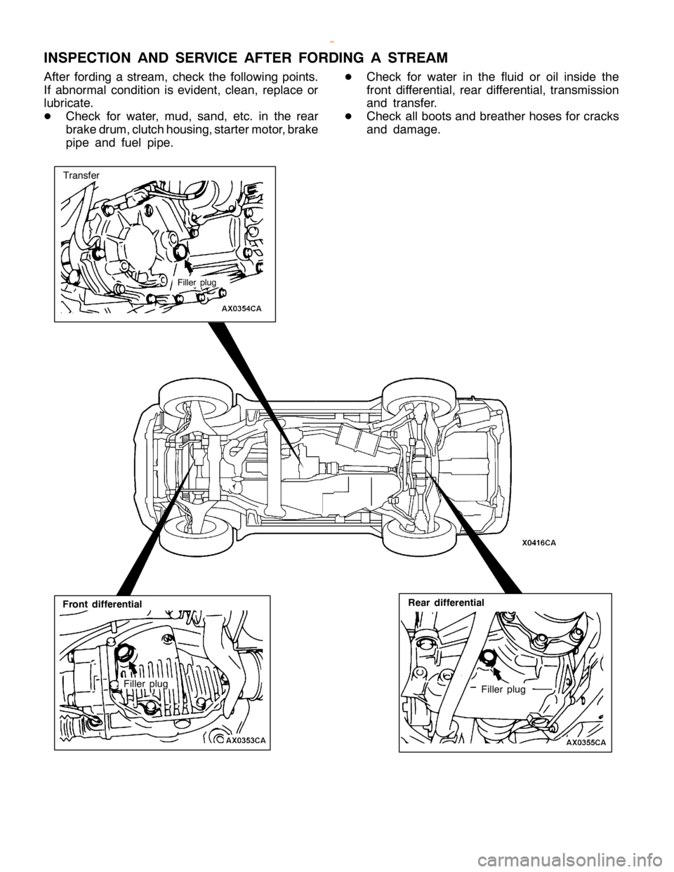
R EATM EN T BEFO RE/A FTE R FO RDIN G ASTR EA M
I N SPEC TIO N AND SER VIC E BEFO RE FO RDIN G ASTR EA M
D Vehic le s whic h are driv e n th ro ugh wate r, or
w hic h may possib ly be driv e n th ro ugh wate r,
s h ould be su bje cte d to th e fo llo w in g in sp ectio ns
a nd main te nance pro ce dure s in adva nce . D
In sp ect th e dust boot and bre ath er hose fo r
c ra cks or dam age, and re pla ce th em if cra cks
o r dam age are fo und.
Page 16 of 1839

Page 17 of 1839

V
EH IC LE ID EN TIF IC ATIO N
V EH IC LE IN FO RM ATIO N CO DE PLA TE
L O CATIO N
V ehic le in fo rm atio n co de pla te is riv e te d on th e to eboard
i n sid e th e engin e co m partm ent.
C O DE PLA TE DESC RIP TIO N
T he pla te sh ow s model co de, engin e model, tr a nsm is sio n
m odel, and body co lo ur co de.
N o. I
te m C
onte nts 1 M
ODEL V
65W V
65W :V ehic le model M
YH CL6 M
YH CL6: M odelse rie s 2 E
N G IN E 6
G 74G DI E
ngin e model 3 E
XT S
74B E
xte rio r co de 4 T
R AN S
A XLE V
5A 51 T
ra nsm is sio n co de 5 C
O LO R S
74 15Q Z06 S
74: B ody co lo ur co de I
N T OPT 1
5Q :In te rio r co de Z
06: E quip m ent co de E
ngin e model T
ra nsm is sio n m odel F
uels u pply syste m V
64W M
NDFL6 4
D 56 In te rc o ole r Turb o V
5M T1 <5M /T > I
n ye ctio n M
NHFL6 (
2 ,4 77 mL) V
5M 31 <5M /T > M
NHFR 6 M
NXFL6 M
NXFR 6
Page 18 of 1839

GENERAL -Vehicle Identification00-17
Model codeFuel supply system Transmission model Engine model
V68WMNDFL64M41-DOHC Intercool-V5M31<5M/T>Electronically-con-
MNHFL6
er Turbo (3,200 mL)trolled high pressure
fuel distribution
MYHFL6V5A51 <5A/T>
MNXFL6V5M31<5M/T>
MNXFR6
MYXFL6V5A51 <5A/T>
MYXFR6
V65WMNHCL66G74GDI (3,496 mL)V5M31<5M/T>GDI
MNHCR6
MYHCL6V5A51 <5A/T>
MYHCR6
MNXCL6V5M31<5M/T>
MNXCR6
MYXCL6V5A51 <5A/T>
MYXCR6
Model codeEngine modelTransmission modelFuel supply system
V74WLNDFL64D56 Intercooler TurboV5MT1 <5M/T>Inyection
LNHFL6
(2,477 mL)
V5M31<5M/T>
LNXFL6
V78WLNDFL64M41-DOHC Intercool-V5M31<5M/T>Electronically-con-
LNHFL6
er Turbo (3,200 mL)trolled high pressure
fuel distribution
LNHFR6
LYHFL6V5A51 <5A/T>
LYHFR6
LNXFL6V5M31<5M/T>
LNXFR6
LYXFL6V5A51 <5A/T>
LYXFR6
www.WorkshopManuals.co.uk
Purchased from www.WorkshopManuals.co.uk
Page 19 of 1839

V
75W L
N HCL6 6
G 74G DI(3 ,4 96 mL) V
5M 31 <5M /T > G
DI L
N HCR6 L
Y H CL6 V
5A 51 <5A /T > L
Y H CR6 L
N XC L6 V
5M 31 <5M /T > L
N XC R6 L
Y XC L6 V
5A 51 <5A /T > L
Y XC R6 I
te m s C
onte nts 1 D
eve lo pm ent V
: MIT S U BIS H IP A JE R O 2 w
heelb ase 6
: Short w heelb ase 2 w
heelb ase 6
: Short w heelb ase
7 : Long wheelb ase 3 E
ngin e ty p e 4
: 2,4 77 mL die se le ngin e 3 E
ngin e ty p e 4
: 2,4 77 mL die se le ngin e
5 : 3,4 96 mL petr o le ngin e 8
: 3,2 00 mL die se le ngin e 4 S
ort W
: Wagon 5 B
ody sty le M
: 3-d oor 5 B
ody sty le M
: 3-d oor
L : 5-d oor 6 T
ra nsm is sio n ty p e N
: 5-s p eed manual
t r a nsm is sio n
Y : 5-s p eed auto m atic
t r a nsm is sio n 7 T
rim le ve l D
: GL 7 T
rim le ve l D
: GL
H : GLX X
: GLS 8 S
pecif ic a tio n engin e
f e atu re C
: GDI
F : In te rc o ole r Turb och arg er 9 S
te erin g wheello ca tio n L
: Left hand
R : Rig ht hand 1
0 D
estin atio n 6
: For E uro pe
Page 20 of 1839

I
te m s C
onte nts 1 F
ix e d fig ure J A
sia 2 D
is tr ib utio n ch annel M J
a pan ch annel 3 D
estin atio n A F
or E uro pe, rig hth and driv e B F
or E uro pe, le ft hand driv e 4 B
ody sty le M 3
-d oor L 5
-d oor 5 T
ra nsm is sio n ty p e N 5
-s p eed manualtr a nsm is sio n Y 5
-s p eed auto m atic tr a nsm is sio n 6 D
eve lo pm ent ord er V
6 M
IT S U BIS H IP A JE R O sh ort w heelb ase V
7 M
IT S U BIS H IP A JE R O lo ng wheelb ase 7 E
ngin e 4 4
D 56: 2,4 77 mL die se le ngin e 5 6
G 74: 3,4 96 mL petr o le ngin e 8 4
M 41:3 ,2 00 mL die se le ngin e 8 S
ort W S
ta tio n wagon 9 M
odelye ar 1 2
001 1
0 P
la nt J N
agoya -3 1
1 S
eria ln um ber - -