speed sensor MITSUBISHI MONTERO 2000 Service Manual Online
[x] Cancel search | Manufacturer: MITSUBISHI, Model Year: 2000, Model line: MONTERO, Model: MITSUBISHI MONTERO 2000Pages: 1839, PDF Size: 29.19 MB
Page 620 of 1839
DIESEL FUEL <4D5-stepIII>-Troubleshooting13E-10
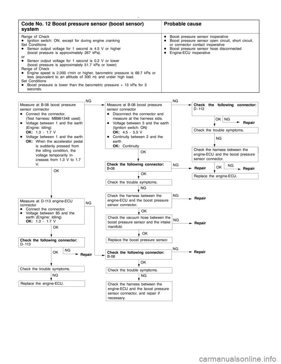
Code No. 12 Boost pressure sensor (boost sensor)
systemProbable cause
Range of Check
DIgnition switch: ON, except for during engine cranking
Set Conditions
DSensor output voltage for 1 second is 4.5 V or higher
(boost pressure is approximately 267 kPa).
or
DSensor output voltage for 1 second is 0.2 V or lower
(boost pressure is approximately 51.7 kPa or lower)
Range of Check
DEngine speed is 2,000 r/min or higher, barometric pressure is 69.7 kPa or
less (equivalent to an altitude of 300 m) and under high load.
Set Conditions
DBoost pressure is lower than the barometric pressure + 13 kPa for 3
seconds.DBoost pressure sensor inoperative
DBoost pressure sensor open circuit, short circuit,
or connector contact inoperative
DBoost pressure sensor hose disconnected
DEngine-ECU inoperative
NG
Check the trouble symptoms.
Replace the engine-ECU.
Check the following connector:
D-113
NGOK
NG
Repair
RepairOK
NG
Check the trouble symptoms.
OKOK
OK
Check the following connector:
B-08NG
Check the trouble symptoms. NG
Repair
NG
NG
Check the vacuum hose between the
boost pressure sensor and the intake
manifold.
Replace the boost pressure sensor.
OK OK OK
Repair
NG
Repair
Check the trouble symptoms.
Check the harness between the
engine-ECU and the boost pressure
sensor connector, and repair if
necessary.
NG OK
NG
RepairCheck the following connector:
B-08NG
Measure at B-08 boost pressure
sensor connector
DConnect the connector.
(Test harness: MB991348 used)
DVoltage between 1 and the earth
(Engine: Idling)
OK:1.3 - 1.7 V
DVoltage between 1 and the earth
OK:When the accelerator pedal
is suddenly pressed from
the idling condition, the
voltage temporarily in-
creases from 1.3 V to 1.7
V.
Measure at D-113 engine-ECU
connector
DConnect the connector.
DVoltage between 85 and the
earth (Engine: Idling)
OK:1.3 - 1.7 V
Check the harness between the
engine-ECU and the boost pressure
sensor connector.
Measure at B-08 boost pressure
sensor connector
DDisconnect the connector and
measure at the harness side.
DVoltage between 3 and the earth
(Ignition switch: ON)
OK:4.5 - 5.5 V
DContinuity between 2 and the
earth
OK:Continuity
Replace the engine-ECU.NGCheck the harness between the
engine-ECU and the boost pressure
sensor connector.
Replace the engine-ECU.OK
NG
Repair
Check the following connector:
D-112
www.WorkshopManuals.co.uk
Purchased from www.WorkshopManuals.co.uk
Page 623 of 1839
DIESEL FUEL <4D5-stepIII>-Troubleshooting13E-13
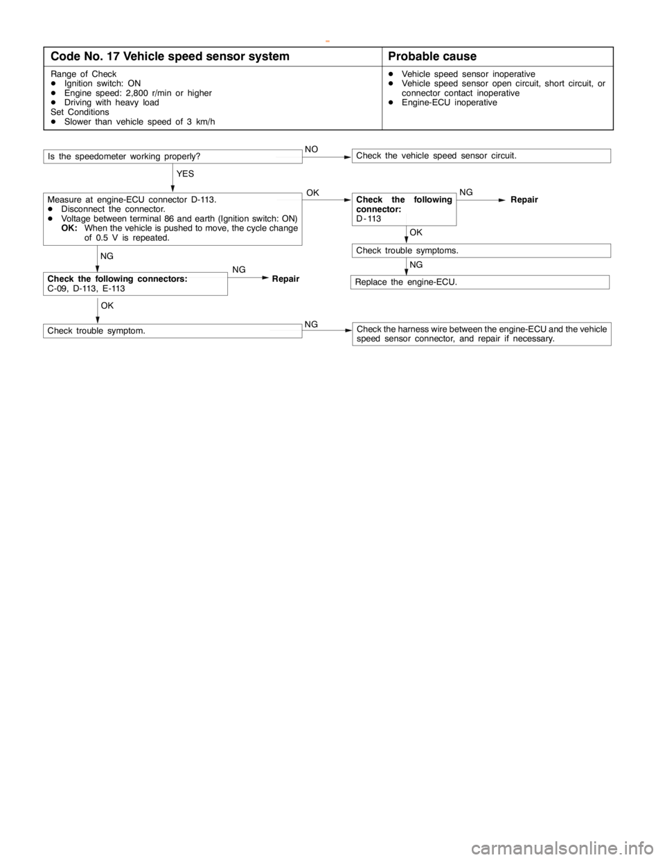
Code No. 17 Vehicle speed sensor systemProbable cause
Range of Check
DIgnition switch: ON
DEngine speed: 2,800 r/min or higher
DDriving with heavy load
Set Conditions
DSlower than vehicle speed of 3 km/hDVehicle speed sensor inoperative
DVehicle speed sensor open circuit, short circuit, or
connector contact inoperative
DEngine-ECU inoperative
Replace the engine-ECU.
NG
OK
Check trouble symptoms.
NG
OK
Check trouble symptom.
NG
Check the following connectors:
C-09, D-113, E-113NG
Repair
YES
Measure at engine-ECU connector D-113.
DDisconnect the connector.
DVoltage between terminal 86 and earth (Ignition switch: ON)
OK:When the vehicle is pushed to move, the cycle change
of 0.5 V is repeated.Check the following
connector:
D-113NG
Repair
Is the speedometer working properly?NO
Check the harness wire between the engine-ECU and the vehicle
speed sensor connector, and repair if necessary.
Check the vehicle speed sensor circuit.
OK
www.WorkshopManuals.co.uk
Purchased from www.WorkshopManuals.co.uk
Page 624 of 1839
DIESEL FUEL <4D5-stepIII>-Troubleshooting13E-14
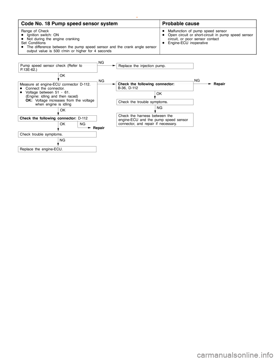
Code No. 18 Pump speed sensor systemProbable cause
Range of Check
DIgnition switch: ON
DNot during the engine cranking
Set Conditions
DThe difference between the pump speed sensor and the crank angle sensor
output value is 500 r/min or higher for 4 secondsDMalfunction of pump speed sensor
DOpen circuit or short-circuit in pump speed sensor
circuit, or poor sensor contact
DEngine-ECU inoperative
NG
Replace the engine-ECU.OK
Check trouble symptoms.NG
Repair
NG
Check the harness between the
engine-ECU and the pump speed sensor
connector, and repair if necessary.
OK
Replace the injection pump.
OK
Measure at engine-ECU connector D-112.
DConnect the connector.
DVoltage between 51 - 61.
(Engine: idling and then raced)
OK:Voltage increases from the voltage
when engine is idlingNGCheck the following connector:
B-36, D-112NG
Repair
OK
NGPump speed sensor check (Refer to
P.13E-62.)
Check the following connector:D-112
Check the trouble symptoms.
www.WorkshopManuals.co.uk
Purchased from www.WorkshopManuals.co.uk
Page 625 of 1839
DIESEL FUEL <4D5-stepIII>-Troubleshooting13E-15
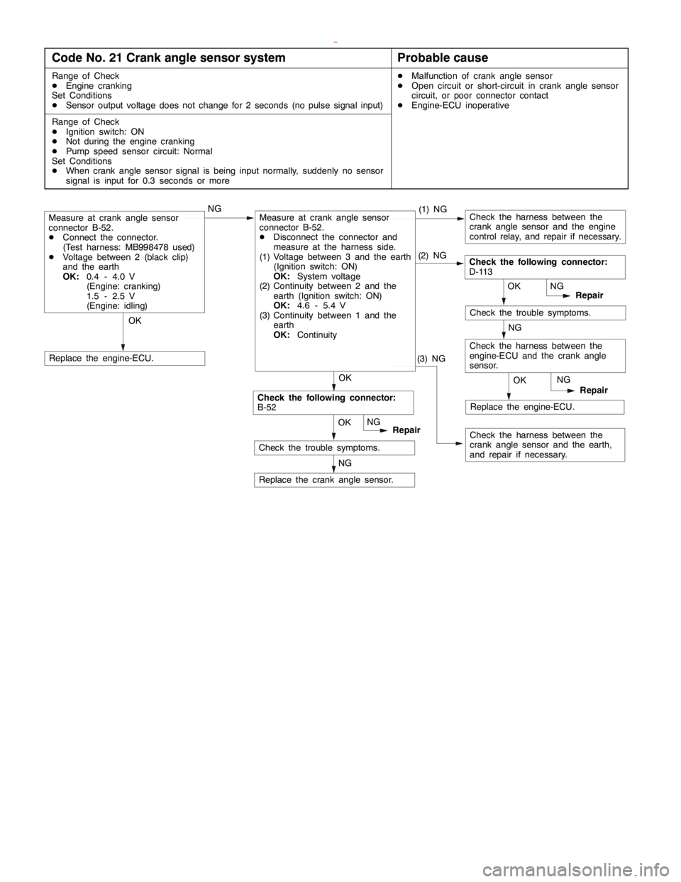
Code No. 21 Crank angle sensor systemProbable cause
Range of Check
DEngine cranking
Set Conditions
DSensor output voltage does not change for 2 seconds (no pulse signal input)DMalfunction of crank angle sensor
DOpen circuit or short-circuit in crank angle sensor
circuit, or poor connector contact
DEngine-ECU inoperative
Range of Check
DIgnition switch: ON
DNot during the engine cranking
DPump speed sensor circuit: Normal
Set Conditions
DWhen crank angle sensor signal is being input normally, suddenly no sensor
signal is input for 0.3 seconds or more
OK
Check the harness between the
crank angle sensor and the engine
control relay, and repair if necessary.
OKNG(1) NGMeasure at crank angle sensor
connector B-52.
DConnect the connector.
(Test harness: MB998478 used)
DVoltage between 2 (black clip)
and the earth
OK:0.4 - 4.0 V
(Engine: cranking)
1.5 - 2.5 V
(Engine: idling)
NG
Replace the crank angle sensor.
Replace the engine-ECU.
OKRepair
Check the following connector:
D-113
NG
OK
Repair NG
Check the harness between the
engine-ECU and the crank angle
sensor.NG
Check the trouble symptoms.
Replace the engine-ECU.
Check the harness between the
crank angle sensor and the earth,
and repair if necessary. OKRepair NG
Check the following connector:
B-52
Check the trouble symptoms.
Measure at crank angle sensor
connector B-52.
DDisconnect the connector and
measure at the harness side.
(1) Voltage between 3 and the earth
(Ignition switch: ON)
OK:System voltage
(2) Continuity between 2 and the
earth (Ignition switch: ON)
OK:4.6 - 5.4 V
(3) Continuity between 1 and the
earth
OK:Continuity(2) NG
(3) NG
www.WorkshopManuals.co.uk
Purchased from www.WorkshopManuals.co.uk
Page 651 of 1839

DIESEL FUEL <4D5-stepIII>-Troubleshooting13E-41
Item
No.Reference
page Code No.
or inspec-
tion proce-
dure No. Value to be
determined
as normal Inspection conditions Check item
06Vehicle
speed
sensorWhen drivingCompare the engine
speed displayed in the
speed meter with that
in MUT-IIMatchedCode No.
1713E-13
07Pump
speedEngine: CrankingCompare the engine
speed displayed in theMatchedCode No.
1813E-14
speed
sensorEngine: Idling
speeddisplayedinthe
tachometer with that in
MUT-II
18
08Crank angle
sensorEngine: CrankingCompare the engine
speed displayed in theMatchedCode No.
2113E-15
sensor
Engine: Idling
speeddisplayedinthe
tachometer with that in
MUT-II
21
09Accelerator
pedal posi-
tionsensor
Ignition switch: ONAccelerator pedal:
Idling position1,015 - 1,055
mVCode No.
1113E-9
tion sensor
(main)Accelerator pedal:
Fully opened position4,035 - 4,500
mV or higher
10Accelerator
pedal posi-
ti
Ignition switch: ONAccelerator pedal:
Idling position0%Code No.
1113E-9
pp
tion sensor
(main)Accelerator pedal:
Fully opened position99 - 100 %
11System volt-
ageIgnition switch: ONSystem volt-
ageProcedure
No. 2013E-37
13Timing
tl
Engine: After warming
thi
Idling70 - 90 %Code No.
25N
13E-17g
control
valve*1
gg
up the engineWhen engine is
suddenly racedChanges25 or No.
4313E-21
14EGR com-
dl
Engine: After warming
thi
Idling0 - 100 %*2–-
mand value
gg
up the engineWhen engine is
suddenly racedMomentarily
decreases
17Control
sleeve posi-Engine: After warming
up the engineIdling2.1 - 2.5 VCode No.
2613E-18
sleeveposi
tion (target
value)
uptheengine
2,500 r/min (no load)1.8 - 2.2 V
26
18Actual injec-
titi i
Engine: After warming
thi
Idling0.7 - 1.2 V––j
tion timing
gg
up the engineWhen engine is
suddenly racedIncreases
19Injection
ti i
Engine: After warming
thi
Idling0.7 - 1.2 V––j
timing com-
mand value
gg
up the engineWhen engine is
suddenly racedIncreases
21GE actuatorEngine: After warming
uptheengine
Idling0%Code No.
26orNo
13E-18
13E 23upthe engine2,500 r/min18 - 38 %26orNo.
4813E-23
23Control
sleeve posi-Engine: After warming
up the engineIdling2.1 - 2.5 VCode No.
2613E-18
sleeveposi
tion (actual
l)
uptheengine
2,500 r/min (no load)1.8 - 2.2 V
26
(
value)2,500r/min(noload)1.82.2V
24Accelerator
pedal posi-
ti
Ignition switch: ONAccelerator pedal:
Idling position1,015 - 1,055
mVCode No.
2713E-19
pp
tion sensor
(sub)Accelerator pedal:
Fully opened position4,035 - 4,500
mV or higher
www.WorkshopManuals.co.uk
Purchased from www.WorkshopManuals.co.uk
Page 654 of 1839

DIESEL FUEL <4D5-stepIII>-Troubleshooting13E-44
ACTUATOR TEST TABLE
Item
No.Check itemDrive Con-
tentsInspection
conditionsValue to be determined
as normalCode No.
or inspec-
tion proce-
dure No.Reference
page
02Glow plug relayTurning the
relayfrom
Ignition switch:
ON
Battery charge is
energizedtotheglow
Procedure
No24
13E-39
relayfrom
OFF to ON or
fromONto
ONenergizedtotheglow
plug when the glow
plugrelayisON
No.24
fromONto
OFFplug relayisON.
03A/C compressor
relay
Turning the
relayfrom
Ignition switch:
ON
The A/C compressor
clutchmakesan
Procedure
No25
13E-39
relayrelayfrom
OFF to ON or
fromONto
ONclutchmakes an
audible sound.No.25
fromONto
OFF
11Timing control
valveTurn the
timing control
valve to ONDIgnition
switch: ON
DEngine:
Idlin
g
Makes an audible
soundCode No.
4313E-21
12Turn the
timing control
valve to OFF
Idling
DTimer piston
position
sensor:
Normal
15Glow lampTurn the glow
lamp on or offIgnition switch:
ONThe glow lamp turns
on.––
16Warning lampTurn the
warning lamp
on or offIgnition switch:
ONThe warning lamp
turns on.Procedure
No. 3, 413E-30
22Condenser fan
relayTurning the
relay from
OFF to ON or
from ON to
OFFIgnition switch:
ONThe condenser fan
rotates.Procedure
No. 1913E-36
23Throttle solenoid
valveTurn the
solenoid
valve from
OFF to ON or
from ON to
OFFDIgnition
switch: ON
DVehicle
speed:
0 km/h
DEngine
speed:
1,000 r/min
or lowerMakes an audible
soundCode No.
4113E-20
25GE actuatorTurn the GE
actuator to
ONDIgnition
switch: ON
DEngine
speed:
0 r/min orMeasure the wave
pattern between
engine-ECU connec-
tor terminals No. 1
and No. 15 using anCode No.
4813E-23
26Turn the GE
actuator to
OFF
0r/minor
lower
DControl
sleeve posi-
tion sensor:
Normal
andNo.15usingan
analyzer and check
the change in the duty
ratio.
www.WorkshopManuals.co.uk
Purchased from www.WorkshopManuals.co.uk
Page 657 of 1839

DIESEL FUEL <4D5-stepIII>-Troubleshooting13E-47
Terminal
No.Normal condition: Inspection conditions (engine status) Check item
21A/C relayA/C switch: OFF→ONSystem voltage→0-1
V
31Idle switchIgnition switch: ONRelease the foot from the
accelerator pedal.0-1V
Step on the accelerator
pedal slightly3 V or higher
32A/C switchA/C in operation (compressor in operation)System voltage
36Selector switch
between A/T and M/TIgnition switch: ONSystem voltage (M/T)
46Control relayIgnition switch: ON0-1V
Ignition switch: ON→OFF (in about 8 seconds)System voltage
51Pump speed sensorEngine: Idling (Use a digital voltage meter to check.)0V↔5V
(repeat the change)
55Accelerator pedal
position sensor (sub)Ignition switch: ONAccelerator pedal: Idling
position0.9 - 1.1 V
Accelerator pedal: Fully
opened position3.7 V or higher
60Sensor power supplyIgnition switch: ON4.6 - 5.4 V
71Ignition switch-STEngine: Cranking8 V or higher
80Back-up power supplyIgnition switch: OFFSystem voltage
81Power supply to accel-
erator pedal position
sensor (main)Ignition switch: ON4.6 - 5.4 V
82Ignition switch-IGIgnition switch: ONSystem voltage
83Engine coolant tem-
perature sensorIgnition switch: ONEngine coolant
temperature: 0_C3.7 - 4.3 V
Engine coolant
temperature: 20_C2.8 - 3.4 V
Engine coolant
temperature: 40_C1.9 - 2.5 V
Engine coolant
temperature: 80_C0.6 - 1.2 V
84Accelerator pedal posi-
tion sensor (main)Ignition switch: ONAccelerator pedal: Idling
position0.9 - 1.1 V
Accelerator pedal: Fully
opened position3.7 V or higher
85Boost pressure sensorIgnition switch: ON (101 kPa)1.0 - 1.4 V
86Vehicle speed sensorDIgnition switch: ON
DMove the vehicle forward slowly0V↔8 - 12 V
(repeat the change)
87Fuel temperature sen-
sor
Ignition switch: ONFuel temperature: 0_C3.2 - 3.6 V
sorFuel temperature: 20_C2.3 - 2.7 V
Fuel temperature: 40_C1.5 - 1.9 V
Fuel temperature: 80_C0.4 - 0.8 V
www.WorkshopManuals.co.uk
Purchased from www.WorkshopManuals.co.uk
Page 735 of 1839

INTAKE AND EXHAUST -General Information/Service Specifications/Sealant15-3
At starting and driving at low speed, the duty control
value of the variable geometry solenoid valve is
increased to apply the vacuum pressure of the
vacuum pump to the variable geometry actuator.
Applying the vacuum pressure to the variable
geometry actuator pulls the actuator rod so that
it can move towards the direction of closing the
variable nozzle of the variable geometry
turbocharger. As closing the nozzle reduces the
exhaust gas mass, the speed of exhaust gas flow
will be increased and efficiency will be improved.
Since the characteristic of boost pressure becomes
a low speed type, boost pressure will suddenly
rise from low speed.
At driving at high speed, the duty control value
of the variable geometry solenoid valve is
decreased to reduce the vacuum pressure from
the vacuum pump so that the actuator rod can
return to the deactivated status and move towards
the direction of opening the nozzle of the variable
geometry turbocharger.Opening the nozzle allows the characteristic of
boost pressure to become a high speed type so
that the appropriate boost pressure can be
maintained.
Therefore, boost pressure can be controlled by
appropriate duty control of the variable geometry
solenoid valve. The engine-ECU calculates the
correct boost pressure based on the engine speed
and fuel injection amount. Furthermore, the duty
control of the variable geometry solenoid valve is
given feedback of the signals from the variable
geometry control pressure sensor and the boost
pressure sensor so that the variable nozzle opening
angle of the variable geometry turbocharger can
be quickly adjusted to obtain the desired boost
pressure.
SERVICE SPECIFICATIONS
ItemsStandard value
Variable geometry actuator activation vacuum
(Approximately 1 mm stroke) kPaApproximately 10.5 - 12.5
Variable geometry solenoid valve coil resistance
(at 20°C)Ω29 - 35
SEALANT
ItemSpecified sealantRemarks
Thread of the intake manifold mounting
bolts3M Stud Locking No.4170 or equivalentAnaerobic sealant
www.WorkshopManuals.co.uk
Purchased from www.WorkshopManuals.co.uk
Page 804 of 1839

17-2
EVAPORATIVE EMISSION CONTROL
SYSTEM 36..............................
General Information 36......................
System Diagram 36.........................
Component Location 36......................
Purge Control System Check 37..............
Purge Port Vacuum Check 37................
Purge Control Solenoid Valve Check 38.......
EXHAUST GAS RECIRCULATION (EGR)
SYSTEM 39..............................
General Information 39......................
Operation 39................................
System Diagram 39.........................
Component Location 39......................
Exhaust Gas Recirculation (EGR) Control
System Check 40...........................
EGR Valve (Stepper Motor) Check 40........
EGR VALVE 42...........................
CANISTER 43............................
CATALYTIC CONVERTER 44..............
General Information 44......................
EMISSION CONTROL SYSTEM
<4D5> 45.............................
GENERAL INFORMATION 45..............
SERVICE SPECIFICATIONS 45............
SEALANT 45.............................
SPECIAL TOOL 45.......................
EXHAUST GAS RECIRCULATION (EGR)
SYSTEM 46..............................
General Information 46......................
System Diagram 46.........................
Component Location 46......................
Function Check 47..........................
EGR Solenoid Valve Operation Check 47.....
EGR Solenoid Valve Resistance Check 48....
Lever Position Sensor (LPS) Adjustment 48...
Engine Speed Sensor Check 49..............
Engine Coolant Temperature Sensor
Check 49...................................
CHECK AT THE GLOW & EGR CONTROL
UNIT 51..................................
EMISSION CONTROL SYSTEM
<4M4-VEHICLES WITH EGR> 52........
GENERAL INFORMATION 52..............
SERVICE SPECIFICATIONS 52............
EXHAUST GAS RECIRCULATION (EGR)
SYSTEM 53..............................
General Information 53......................
System Diagram 53.........................
Component Location 53......................
Function Check 54..........................
EGR Solenoid Valve Operation Check 54.....
EGR Solenoid Valve Resistance Check 55....
Accelerator Pedal Position Sensor (APS),
Engine Coolant Temperature Sensor, Intake
Air Temperature Sensor, Fuel Temperature
Sensor Check 55............................
Check at Engine-ECU 55....................
CATALYTIC CONVERTER 55..............
General Information 55......................
www.WorkshopManuals.co.uk
Purchased from www.WorkshopManuals.co.uk
Page 814 of 1839
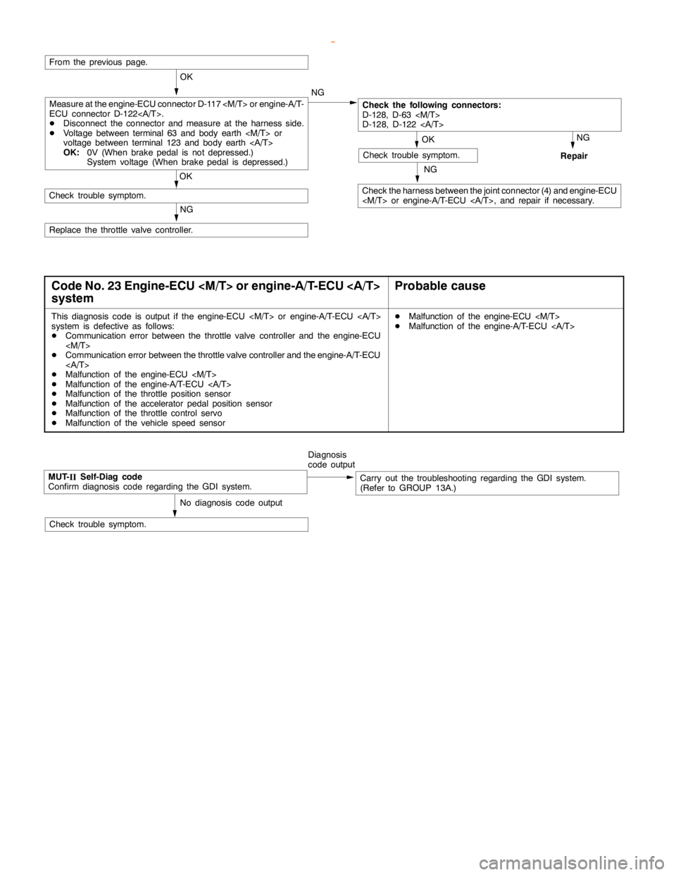
ENGINE AND EMISSION CONTROL -Auto-cruise Control System17-12
NG
Check the harness between the joint connector (4) and engine-ECU
NG
Repair
OK
Check trouble symptom.
From the previous page.
OK
Check the following connectors:
D-128, D-63
D-128, D-122
OK
Check trouble symptom.
NG
Replace the throttle valve controller.NG
Measure at the engine-ECU connector D-117
ECU connector D-122.
DDisconnect the connector and measure at the harness side.
DVoltage between terminal 63 and body earth
voltage between terminal 123 and body earth
OK:0V (When brakepedal is not depressed.)
System voltage (When brakepedal is depressed.)
Code No. 23 Engine-ECU
systemProbable cause
This diagnosis code is output if the engine-ECU
system is defective as follows:
DCommunication error between the throttle valve controller and the engine-ECU
DCommunication error between the throttle valve controller and the engine-A/T-ECU
DMalfunction of the engine-ECU
DMalfunction of the engine-A/T-ECU
DMalfunction of the throttle position sensor
DMalfunction of the accelerator pedal positionsensor
DMalfunction of the throttle control servo
DMalfunction of the vehicle speed sensorDMalfunction of the engine-ECU
DMalfunction of the engine-A/T-ECU
MUT-
IISelf-Diag code
Confirm diagnosis code regarding the GDI system.Diagnosis
code outputCarry out the troubleshooting regarding the GDI system.
(Refer to GROUP 13A.)
No diagnosis code output
Check trouble symptom.
www.WorkshopManuals.co.uk
Purchased from www.WorkshopManuals.co.uk