speed sensor MITSUBISHI MONTERO 2000 Service Repair Manual
[x] Cancel search | Manufacturer: MITSUBISHI, Model Year: 2000, Model line: MONTERO, Model: MITSUBISHI MONTERO 2000Pages: 1839, PDF Size: 29.19 MB
Page 1624 of 1839

CHASSIS ELECTRICAL -Clock or Center Display54A-54
BEFORE REMOVING THE BATTERY
The Center display has a large amount of data unique to the vehicle in its memory. When the battery
cable is disconnected, that memory is affected as shown in the table below. Accordingly, it is necessary
to make sure that you take notes of important information before disconnecting the battery cable.
FunctionInput function/memoryWhen battery cable is disconnected
Clock set on displayCurrent timeRetains data for approx. 1 hour
Vehicle model setShort (3-door models)/long (5-door
models)Retains data for approx. 1 hour
Brightness set for displayPosition set on displayRetains data for approx. 1 hour
Unit set for trip computerkm or mile, L/100km or mpg or km/L
Average vehicle speed after resetRetains data for approx. 1 hour
Average vehicle speed on displayAverage vehicle speed after resetRetains data for approx. 1 hour
Average fuel consumption on displayAverage fuel consumption after resetRetains data for approx. 1 hour
Cruising range on displayCruising range, fuel economyRetains data for approx. 1 hour
Outside temperature on displayOutside temperature after the ignition
switch is turned to the OFF(LOCK)
position.Retains data for approx. 1 hour
* The outside temperature sensor
is located near the engine.
Therefore, incorrectly high
temperature may be displayed
when the battery cable is
reconnected within one hour.
DIAGNOSIS FUNCTION FOR CENTER DISPLAY
Center display has the following diagnosis function:
FunctionContents
Service functionThere are the following 4 diagnosis modes available
1. Check of vehicle informationThe vehicle, short (3-door models)/long (5-door models) set
2. Check of LCD segmentsThe LCD segments for display available to light on or not
3. Check of sensorsOutside temperature, voltage of fuel gauge unit, system voltage, fuel amount
remains, fuel economy calculated after supply of fuel
4. Check of units connected into
the center displayThe units connected on display
Voltage (%) on terminal for MUT-II
Vehicle speed signal sent by engine-ECU
Oscillating signal
www.WorkshopManuals.co.uk
Purchased from www.WorkshopManuals.co.uk
Page 1632 of 1839

CHASSIS ELECTRICAL -Clock or Center Display54A-62
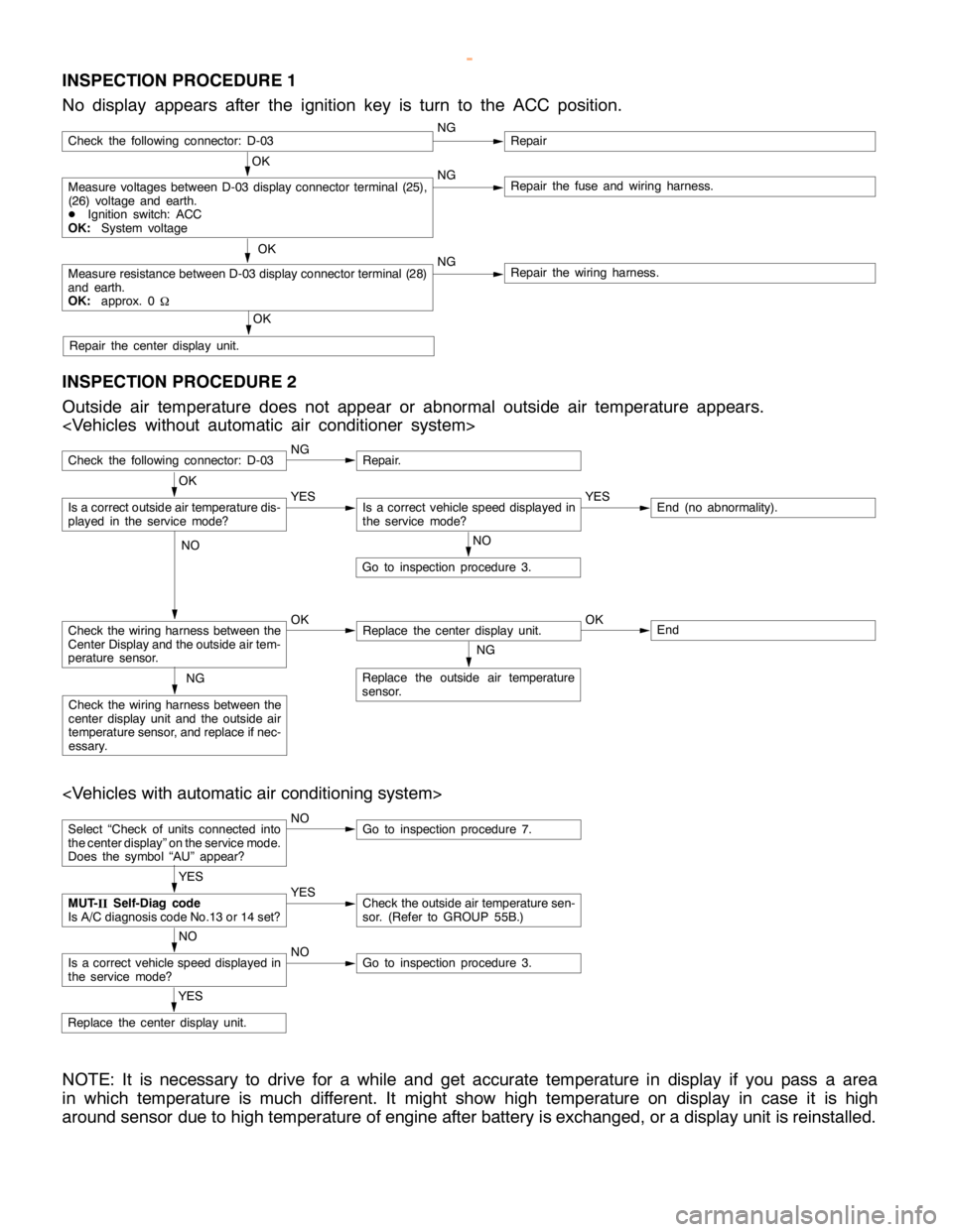
INSPECTION PROCEDURE 1
No display appears after the ignition key is turn to the ACC position.
OK
Measure voltages between D-03 display connector terminal (25),
(26) voltage and earth.
DIgnition switch: ACC
OK:System voltageNGRepair the fuse and wiring harness.
OK
Measure resistance between D-03 display connector terminal (28)
and earth.
OK:approx. 0
WNGRepair the wiring harness.
OK
Repair the center display unit.
Check the following connector: D-03NGRepair
INSPECTION PROCEDURE 2
Outside air temperature does not appear or abnormal outside air temperature appears.
Check the following connector: D-03NGRepair.
NO
Go to inspection procedure 3.
Check the wiring harness between the
Center Display and the outside air tem-
perature sensor.OKReplace the center display unit.OKEnd
NG
Replace the outside air temperature
sensor.NG
Check the wiring harness between the
center display unit and the outside air
temperature sensor, and replace if nec-
essary.
OK
Is a correct outside air temperature dis-
played in the servicemode?YESIs a correct vehicle speed displayed in
the servicemode?YESEnd (no abnormality).
NO
Select “Check of units connected into
the center display” on the service mode.
Does the symbol “AU” appear?NOGo to inspection procedure 7.
YES
Replace the center display unit.
YES
MUT-
IISelf-Diag code
Is A/C diagnosis code No.13 or 14 set?YESCheck the outside air temperature sen-
sor. (Refer to GROUP 55B.)
NO
Is a correct vehicle speed displayed in
the servicemode?NOGo to inspection procedure 3.
NOTE: It is necessary to drive for a while and get accurate temperature in display if you pass a area
in which temperature is much different. It might show high temperature on display in case it is high
around sensor due to high temperature of engine after battery is exchanged, or a display unit is reinstalled.
www.WorkshopManuals.co.uk
Purchased from www.WorkshopManuals.co.uk
Page 1633 of 1839

CHASSIS ELECTRICAL -Clock or Center Display54A-63
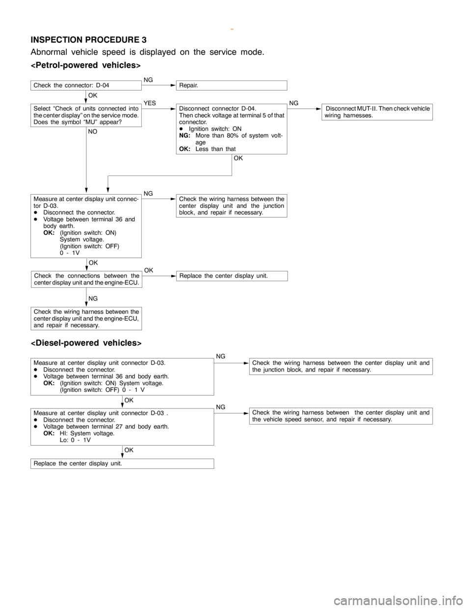
INSPECTION PROCEDURE 3
Abnormal vehicle speed is displayed on the service mode.
OK
NGRepair.
Measure at center display unit connec-
tor D-03.
DDisconnect the connector.
DVoltage between terminal 36 and
body earth.
OK:(Ignition switch: ON)
System voltage.
(Ignition switch: OFF)
0-1VNGCheck the wiring harness between the
center display unit and the junction
block, and repair if necessary.
NG
Check the wiring harness between the
center display unit and the engine-ECU,
and repair if necessary.
Select “Check of units connected into
the center display” on the service mode.
Does the symbol “MU” appear?YES NGDisconnect MUT-
II. Then check vehicle
wiring harnesses.Disconnect connector D-04.
Then check voltage at terminal 5 of that
connector.
DIgnition switch: ON
NG:More than 80% of system volt-
age
OK:Less than that
OK NO
OK
Check the connections between the
center display unit and the engine-ECU.OKReplace the center display unit.
Check the connector: D-04
Measure at center display unit connector D-03.
DDisconnect the connector.
DVoltage between terminal 36 and body earth.
OK:(Ignition switch: ON) System voltage.
(Ignition switch: OFF) 0 - 1 VNGCheck the wiring harness between the center display unit and
the junction block, and repair if necessary.
OK
Measure at center display unit connector D-03 .
DDisconnect the connector.
DVoltage between terminal 27 and body earth.
OK:HI: System voltage.
Lo: 0 - 1VNGCheck the wiring harness between the center display unit and
the vehicle speed sensor, and repair if necessary.
OK
Replace the center display unit.
www.WorkshopManuals.co.uk
Purchased from www.WorkshopManuals.co.uk
Page 1678 of 1839

CHASSIS ELECTRICAL -RV Meter54A-17
Termi-Input/out-
t
Signal sym-
bl
Terminal
lt
Harness problemTrouble symptoms when there is a
hblnal No.
p
put
gy
bolvoltage
(V)Open
circuitshort-cir-
cuit
yp
harness problem
11 - 1 4––––––
15Input/out-
putK (engine
K-LINE
signal)Hi: Sys-
tem volt-
age
Lo:0 - 1ExistsExistsDWiring communication error
DCommunication between the
engine-A/T-ECU
DAbnormal driving information
numerical display
16––––––
17Input/out-
putM-BUSY
(AUDIO)Hi:System
voltage
Lo:0 - 1ExistsExistsDAudio information does not
appear on the screen.
18–SHIELD-
EARTH
(AUDIO)––––
19Input/out-
putM-BUSY
(A/C)Hi:System
voltage
Lo:0 - 1ExistsExistsDAir conditioner information does
not appear on the screen.
DAmbient temperature is not
displayed.
20–SHIELD-
EARTH––––
22 - 21––––––
23InputAmbient
temperature
sensor–ExistsExistsDAmbient temperature is not
displayed.
24InputILL + (Light-
ing switch)Hi:System
voltage
Lo:0 - 1ExistsExistsDoes not illuminate.
25InputACC (ACC
power sup-
l)
System
voltageExists–Screen does not appear. No
operations are possible.
pp
ply)
g
–ExistsBlown multi-purpose fuse
26Input+BSystem
voltageExists–Screen does not appear. No
operations are possible.
g
–ExistsBlown multi-purpose fuse
27InputVSS (Vehicle
speed pulse
signal)Hi:System
voltage
Lo:0 - 1ExistsExistsDAbnormal “Distance km after
replacement” display in mainte-
nance screen
DSwitches which are not
supposed to operate during
driving do operate.
(Example:clock adjustment
screen, maintenance settings,
etc.)
DAmbient temperature display is
abnormally high.
28–Earth–Exists–Screen does not appear.
www.WorkshopManuals.co.uk
Purchased from www.WorkshopManuals.co.uk
Page 1680 of 1839

CHASSIS ELECTRICAL -RV Meter54A-19
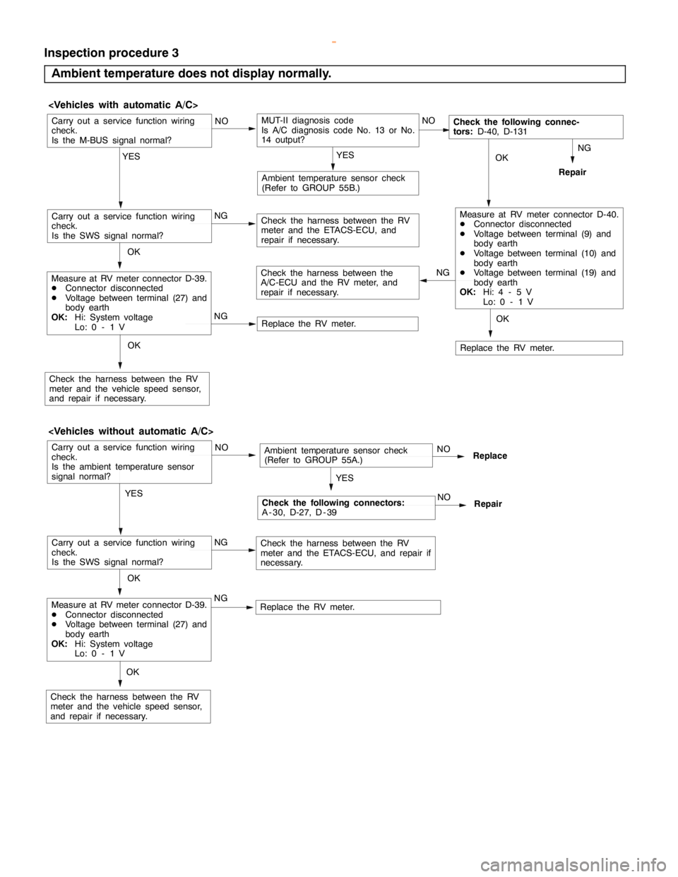
Inspection procedure 3
Ambient temperature does not display normally.
OK
Ambient temperature sensor check
(Refer to GROUP 55B.)
NG
MUT-II diagnosis code
Is A/C diagnosis code No. 13 or No.
14 output?
Repair
Replace the RV meter. NG
Check the harness between the
A/C-ECU and the RV meter, and
repair if necessary.
Carry out a service function wiring
check.
Is the M-BUS signal normal?
YESNO
Replace the RV meter. NGNO
OK
Measure at RV meter connector D-39.
DConnector disconnected
DVoltage between terminal (27) and
body earth
OK:Hi: System voltage
Lo: 0 - 1 V
YES
Check the harness between the RV
meter and the vehicle speed sensor,
and repair if necessary.
Check the following connec-
tors:D-40, D-131
Carry out a service function wiring
check.
Is the SWS signal normal?Check the harness between the RV
meter and the ETACS-ECU, and
repair if necessary.NGMeasure at RV meter connector D-40.
DConnector disconnected
DVoltage between terminal (9) and
body earth
DVoltage between terminal (10) and
body earth
DVoltage between terminal (19) and
body earth
OK:Hi: 4 - 5 V
Lo: 0 - 1 V
OK
OK
Ambient temperature sensor check
(Refer to GROUP 55A.)
NGReplaceCarry out a service function wiring
check.
Is the ambient temperature sensor
signal normal?
YESNO
Replace the RV meter. NGNO
OKMeasure at RV meter connector D-39.
DConnector disconnected
DVoltage between terminal (27) and
body earth
OK:Hi: System voltage
Lo: 0 - 1 V
YES
Check the harness between the RV
meter and the vehicle speed sensor,
and repair if necessary.
Check the following connectors:
A - 30, D-27, D - 39
Carry out a service function wiring
check.
Is the SWS signal normal?Check the harness between the RV
meter and the ETACS-ECU, and repair if
necessary.
OK
NO
Repair
www.WorkshopManuals.co.uk
Purchased from www.WorkshopManuals.co.uk
Page 1820 of 1839

HEATER, AIR CONDITIONER AND VENTILATION -Troubleshooting
DATA LIST REFERENCE TABLE
Item No.Check itemInspection contents
11Inside air temperature sensorIgnition switch: ONInside air temperature and tempera-
ture displayed on the MUT-IIare
identical.
13Outside air temperature sen-
sorIgnition switch: ONOutside air temperature and tem-
perature displayed on the MUT-II
are identical.
15Heater water temperature
sensorIgnition switch: ONHeater core surface temperature
and temperature displayed on the
MUT-IIare identical.
21Air thermo sensorIgnition switch: ONEvaporator outlet temperature and
temperature displayed on the MUT-
IIare identical.
25Photo sensorIgnition switch: ONAmount of incident light is propor-
tional to voltage displayed on the
MUT-II.
31Potentiometer for the air mix
damperIgnition switch: ON
Damper position: MAX HOTOpening angle: Approximately
100%
Ignition switch: ON
Damper position: MAX COOLOpening angle: Approximately 0%
32Potentiometer for the air
outlet changeover damperIgnition switch: ON
Damper position: FACEOpening angle: Approximately 0%
Ignition switch: ON
Damper position:FOOTOpening angle: Approximately 60%
Ignition switch: ON
Damper position: FOOT/DEFOpening angle: Approximately 80%
Ignition switch: ON
Damper position: DEFOpening angle: Approximately
100%
ACTUATOR TEST TABLE
Item No.Check itemDrive Contents
01Blower motorStopped
02Low speed
03Medium speed
04High speed
05Electric motor for the air mix damperOpening angle: Approximately 0%
06Opening angle: Approximately 50%
07Opening angle: Approximately 100%
08Electric motor for the air outlet changeoverFACE
09damperFOOT
10DEF
11Compressor ON/OFFOFF
12ON
13Inside/outside air changeover damper motorOutside air
14Inside air
www.WorkshopManuals.co.uk
Purchased from www.WorkshopManuals.co.uk
Page 1822 of 1839

HEATER, AIR CONDITIONER AND VENTILATION -Troubleshooting
Termi-
nal No.Normal condition Check conditions Check item
15Rear defoggerRear defogger: OFFSystem voltage
Rear defogger: ON1.5 V or less
16Multi center display unit communication
lineIgnition switch: ONHi: 4 - 5 V
Lo: 0 - 1 V
17Multi center display unit communication
lineIgnition switch: ONHi: 4 - 5 V
Lo: 0 - 1 V
18Multi center display unit communication
line shieldAt all times0V
19Diagnosis outputIgnition switch: ONA voltmeter needle
fluctuates between 0
and 12 V.
20Input from A/C compressor relayWhen the A/C is off.0V
When the A/C is in operation
(When compressor is operating)System voltage
21Power supply to potentiometerAt all times5V
22Input from outside air temperature
sensorSensor temperature: 25
_C (1.7 kW)1.9 V
23Input from heater water temperature
sensorSensor temperature: 25
_C(5kW)2.8 V
24Input from potentiometer for air mix
damperWhen the damper flap is moving to the
MAX HOT position.0.7 - 1.3 V
25Power supply to illuminationLighting switch: ONSystem voltage
26Power supply to ignition switch (IG2)Ignition switch: ONSystem voltage
27Power supply to ignition switch (ACC)Ignition switch: ACCSystem voltage
28Backup power supplyAt all timesSystem voltage
29Earth to sensor and potentiometerAt all times0V
30Input from air thermo sensorSensor temperature: 25
_C (1.5 kW)2.2 V
31Photo sensor (+)During 800 kcal/m2-h1V
32Input from potentiometer for the air
outlet changeover damperWhen the damper flap is moving to the
DEF position.0.7 - 1.3 V
33Diagnosis inputIgnition switch: ON0V
34Compressor lock signal (ignition signal)Engine speed: 3 000 r/min0.3 - 3.0
35Illumination earthAt all timesContinuity
36EarthAt all timesContinuity
CHECK AT ENGINE-A/T-ECU OR ENGINE-ECU TERMINALS
Refer to GROUP 13A – Troubleshooting
www.WorkshopManuals.co.uk
Purchased from www.WorkshopManuals.co.uk