clock MITSUBISHI MONTERO 2000 Service Repair Manual
[x] Cancel search | Manufacturer: MITSUBISHI, Model Year: 2000, Model line: MONTERO, Model: MITSUBISHI MONTERO 2000Pages: 1839, PDF Size: 29.19 MB
Page 36 of 1839

GENERAL -Supplemental Restraint System (SRS)00-35
SRS-ECU
Terminal No.Destination of harnessCorrective action
1, 2, 3, 4Instrument panel wiring harness®Front wiring harness®Front
impact sensorRepair or replace each wiring
harness
7Instrument panel wiring harness®EarthRepair or replace Instrument
8Instrument panel wiring harness®Combination meter
(SRS warning lamp)
panel wiring harness
9, 10Instrument panel wiring harness®Front passenger’s air bag
module
11 , 1 2Instrument panel wiring harness®Clock spring®Driver’s air bag
module)Repair or replace the Instrument
panel wiring harness. Replace
clock spring.
13Instrument panel wiring harness®Junction block (fuse No.8)Repair or replace Instrument
16Instrument panel wiring harness®Junction block (fuse No.6)
panel wiring harness.
20Instrument panel wiring harness®Diagnosis connector
21, 22Side air bag wiring harness®Side air bag module (L.H.)Repair or replace side air bag
23, 24Side air bag wiring harness®Side air bag module (R.H.)
wiring harness.
34, 35, 36Side air bag wiring harness®Floor wiring harness®Side impact
sensor (L.H.)Repair or each wiring harness.
40, 41, 42Side air bag wiring harness®Floor wiring harness®Side impact
sensor (R.H.)
6. Inspection of the SRS-ECU harness connector should be carried out by the following procedure.
Insert the special tool (probe, MB991222, in the harness set) into the connector from harness side
(rear side), and connect the tester to this probe. If any tool than specified is used, damage to the
harness and other components will result. Furthermore, measurement should not be carried out by
touching the probe directly against the terminals from the front of the connector. The terminals are
plated to increase their conductivity, so that if they are touched directly by the probe, the plating
may break, which will cause drops in reliability.
www.WorkshopManuals.co.uk
Purchased from www.WorkshopManuals.co.uk
Page 53 of 1839

GENERAL -Precautions Before Service00-5
PRECAUTIONS BEFORE SERVICE
SUPPLEMENTAL RESTRAINT SYSTEM (SRS), SEAT BELT WITH PRE-TENSIONER
1. Items to follow when servicing SRS
(1) Be sure to read GROUP 52B - Supplemental Restraint System (SRS).
For safe operations, please follow the directions and heed all warnings.
(2) Wait at least 60 seconds after disconnecting the battery cable before doing any further work.
The SRS system is designed to retain enough voltage to deploy the air bag even after the battery
has been disconnected. Serious injury may result from unintended air bag deployment if work
is done on the SRS system immediately after the battery cable is disconnected.
(3) Warning labels must be heeded when servicing or handling SRS components and seat belt with
pre-tensioner. Warning labels are located in the following locations.
DHood
DSun visor
DGlove box
DSRS-ECU
DSteering wheel
DSteering gearbox
DAir bag module (driver’s side and front passenger’s side)
DFront impact sensor
DClock spring
DSeat belt with pre-tensioner
DSide air bag module
DSide impact sensor
(4) Always use the designated special tools and test equipment.
(5) Store components removed from the SRS and seat belt with pre-tensioner in a clean and dry
place.
The air bag module and seat belt with pre-tensioner should be stored on a flat surface and
placed so that the pad surface is facing upward.
Do not place anything on top of it.
(6) Never attempt to disassemble or repair the SRS components (SRS-ECU, air bag module, clock
spring and side impact sensor) and seat belt with pre-tensioner.
(7) Whenever you finish servicing the SRS and seat belt with pre-tensioner, check the SRS warning
lamp operation to make sure that the system functions properly.
(8) Be sure to deploy the air bag and seat belt with pre-tensioner before disposing of the air bag
module and seat belt with pre-tensioner or disposing of a vehicle equipped with an air bag and
seat belt with pre-tensioner. (Refer to GROUP 52B - Air Bag Module and Seat Belt with Pre-tensioner
Disposal Procedures.)
2. Observe the following when carrying out operations on places where SRS components and seat
belt with pre-tensioner are installed, including operations not directly related to the SRS air bag and
seat belt with pre-tensioner.
(1) When removing or installing parts do not allow any impact or shock to the SRS components
and seat belt with pre-tensioner.
(2) SRS components and seat belt with pre-tensioner should not be subjected to heat, so remove
the SRS components and seat belt with pre-tensioner before drying or baking the vehicle after
painting.
DSRS-ECU, air bag module, clock spring, front and side impact sensors: 93_C or more
DSeat belt with pre-tensioner: 90_C or more
After re-installing them, check the SRS warning lamp operation to make sure that the system
functions properly.
www.WorkshopManuals.co.uk
Purchased from www.WorkshopManuals.co.uk
Page 383 of 1839
Page 515 of 1839
DIESEL FUEL <4M4> -Troubleshooting13C-24
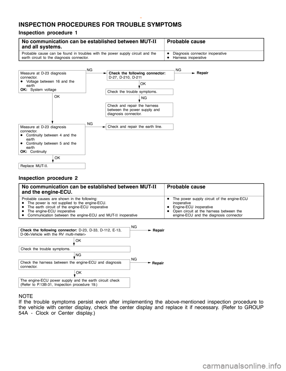
INSPECTION PROCEDURES FOR TROUBLE SYMPTOMS
Inspection procedure 1
No communication can be established between MUT-II
and all systems.
Probable cause
Probable cause can be found in troubles with the power supply circuit and the
earth circuit to the diagnosis connector.DDiagnosis connector inoperative
DHarness inoperative
OK
Check and repair the earth line.
OK
Replace MUT-II.
NG
Check and repair the harness
between the power supply and
diagnosis connector.
OK
Check the trouble symptoms.NG
Repair
NGCheck the following connector:
D-27, D-210, D-211
NGMeasure at D-23 diagnosis
connector.
DVoltage between 16 and the
earth
OK:
System voltage
Measure at D-23 diagnosis
connector.
DContinuity between 4 and the
earth
DContinuity between 5 and the
earth
OK:
Continuity
Inspection procedure 2
No communication can be established between MUT-II
and the engine-ECU.
Probable cause
Probable causes are shown in the following:
DThe power is not supplied to the engine-ECU.
DThe earth circuit of the engine-ECU inoperative
DThe engine-ECU inoperative
DCommunication between the engine-ECU and MUT-IIinoperativeDThe power supply circuit of the engine-ECU
inoperative
DEngine-ECU inoperative
DOpen circuit at the harness between the
engine-ECU and the diagnosis connector
NG
Check the harness between the engine-ECU and diagnosis
connector.NGRepair
OK
Check the trouble symptoms.
Check the following connector:
D-23, D-33, D-112, E-13,
D-06
Repair
OK
The engine-ECU power supply and the earth circuit check
(Refer to P.13B-31, Inspection procedure 19.)
NOTE
If the trouble symptoms persist even after implementing the above-mentioned inspection procedure to
the vehicle with center display, check the center display and replace it if necessary. (Refer to GROUP
54A - Clock or Center display.)
www.WorkshopManuals.co.uk
Purchased from www.WorkshopManuals.co.uk
Page 529 of 1839

DIESEL FUEL <4M4> -Troubleshooting13C-38
Item
No.Reference
page Code No.
or inspec-
tion proce-
dure No. Value to be determined
as normal Inspection
conditions Drive Con-
tents Check item
25GE actuatorTurn the GE
actuator to
ONDIgnition
switch: ON
DEngine
speed:
0 r/min orMakes an audible
soundCode
No.4813C-21
26Turn the GE
actuator to
OFF
0 r/min or
lower
DControl
sleeve posi-
tion sensor:
Normal
27Fuel cut solenoid
valveTurn the
solenoid
valve to ONDIgnition
switch: ON
DVehicle
speed:
0 km/hMakes an audible
sound––
28EGR solenoid
valve No.1Turn the
solenoid
valve to ONDIgnition
switch: ON
DVehicleMakes an audible
sound––
29Turn the
solenoid
valve to ONspeed:
0 km/h
30EGR solenoid
valve No.2Turn the
solenoid
valve from
OFF to ON or
from ON to
OFFDIgnition
switch: ON
DVehicle
speed:
0 km/hMakes an audible
sound––
33PTC heaterSwitch the
PTC heater
relay ON/
OFF.DIgnition
switch: ONVoltage on the ECU
terminal No.9: 0 - 1V––
34Middle position
of GE actuatorHold the
injection
governor in
its middle
position.DIgnition
switch: ONWhen the crankshaft
is turned clockwise
during the adjustment
of the injection timing,
the injection pipes
spray out fuel.Code
No.4813C-21
www.WorkshopManuals.co.uk
Purchased from www.WorkshopManuals.co.uk
Page 590 of 1839

13E-1
MITSUBISHI STABILITY
CONTROL
(MITSUBISHI SC)
CONTENTS
GENERAL INFORMATION 2................
SERVICE SPECIFICATIONS 4..............
SPECIAL TOOLS 4........................
TROUBLESHOOTING 5....................
ON-VEHICLE SERVICE 18.................
Operation Test of MITSUBISHI SC 18.........Wheel Speed Sensor (FR) Check 18..........
Vehicle Speed Sensor Check 18..............
SC-ECU* 19...............................
G SENSOR 20.............................
WHEEL SPEED SENSOR (FR) 20..........
VEHICLE SPEED SENSOR 20..............
WARNINGS REGARDING SERVICING OF SUPPLEMENTAL RESTRAINT SYSTEM (SRS) EQUIPPED VEHICLES
WARNING!
(1) Improper service or maintenance of any component of the SRS, or any SRS-related component, can lead to personal
injury or death to service personnel (from inadvertent firing of the air bag) or to the driver and passenger (from rendering
the SRS inoperative).
(2) Service or maintenance of any SRS component or SRS-related component must be performed only at an authorized
MITSUBISHI dealer.
(3) MITSUBISHI dealer personnel must thoroughly review this manual, and especially its GROUP 52B - Supplemental
Restraint System (SRS) before beginning any service or maintenance of any component of the SRS or any SRS-related
component.
NOTE
The SRS includes the following components: front impact sensors, SRS-ECU, SRS warning lamp, air bag module, clock spring and
interconnecting wiring. Other SRS-related components (that may have to be removed/installed in connection with SRS service or
maintenance) are indicated in the table of contents by an asterisk (*).
www.WorkshopManuals.co.uk
Purchased from www.WorkshopManuals.co.uk
Page 639 of 1839
DIESEL FUEL <4D5-stepIII>-Troubleshooting13E-29
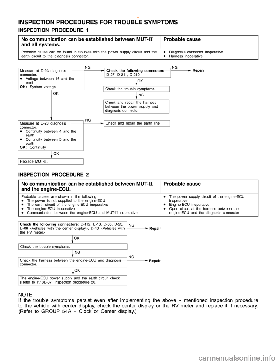
INSPECTION PROCEDURES FOR TROUBLE SYMPTOMS
INSPECTION PROCEDURE 1
No communication can be established between MUT-II
and all systems.
Probable cause
Probable cause can be found in troubles with the power supply circuit and the
earth circuit to the diagnosis connector.DDiagnosis connector inoperative
DHarness inoperative
OK
Check and repair the earth line.
OK
Replace MUT-II.
NG
Check and repair the harness
between the power supply and
diagnosis connector.
OK
Check the trouble symptoms.NG
Repair
NGCheck the following connectors:
D-27, D-211, D-210
NGMeasure at D-23 diagnosis
connector.
DVoltage between 16 and the
earth
OK:System voltage
Measure at D-23 diagnosis
connector.
DContinuity between 4 and the
earth
DContinuity between 5 and the
earth
OK:Continuity
INSPECTION PROCEDURE 2
No communication can be established between MUT-II
and the engine-ECU.
Probable cause
Probable causes are shown in the following:
DThe power is not supplied to the engine-ECU.
DThe earth circuit of the engine-ECU inoperative
DThe engine-ECU inoperative
DCommunication between the engine-ECU and MUT-IIinoperativeDThe power supply circuit of the engine-ECU
inoperative
DEngine-ECU inoperative
DOpen circuit at the harness between the
engine-ECU and the diagnosis connector
NG
Check the harness between the engine-ECU and diagnosis
connector.NGRepair
OK
Check the trouble symptoms.
Check the following connectors:D-112, E-13, D-33, D-23,
D-06
Repair
OK
The engine-ECU power supply and the earth circuit check
(Refer to P.13E-37, Inspection procedure 20.)
NOTE
If the trouble symptoms persist even after implementing the above - mentioned inspection procedure
to the vehicle with center display, check the center display or the RV meter and replace it if necessary.
(Refer to GROUP 54A - Clock or Center display.)
www.WorkshopManuals.co.uk
Purchased from www.WorkshopManuals.co.uk
Page 655 of 1839

DIESEL FUEL <4D5-stepIII>-Troubleshooting13E-45
Item
No.Reference
page Code No.
or inspec-
tion proce-
dure No. Value to be determined
as normal Inspection
conditions Drive Con-
tents Check item
27Fuel cut solenoid
valveTurn the
solenoid
valve from
OFF to ON or
from ON to
OFF.DIgnition
switch: ON
DVehicle
speed:
0 km/hMakes an audible
sound––
34Middle position
of GE actuatorHold the
injection
governor in
its middle
position.DIgnition
switch: ONWhen the crankshaft
is turned clockwise
during the adjustment
of the injection timing,
the injection pipes
spray out fuel.Code No.
4813E-23
35Variable
geometry
solenoid valveTurn the
solenoid
valve to ONIgnition switch:
ONMakes an audible
soundCode No.
4913E-24
36Turn the
solenoid
valve to OFFEngine: IdlingOperating sound and
vibration, which
accompany with the
duty activation, cease.
37EGR control
solenoid valve
No. 1Turn the
solenoid
valve from
OFF to ON
from ON to
OFFIgnition switch:
ONMakes an audible
soundProcedure
No. 2213E-38
38EGR control
solenoid valve
No. 2Turn the
solenoid
valve from
OFF to ON
from ON to
OFFIgnition switch:
ONMakes an audible
soundProcedure
No. 2313E-38
www.WorkshopManuals.co.uk
Purchased from www.WorkshopManuals.co.uk
Page 821 of 1839
ENGINE AND EMISSION CONTROL -Auto-cruise Control System17-19
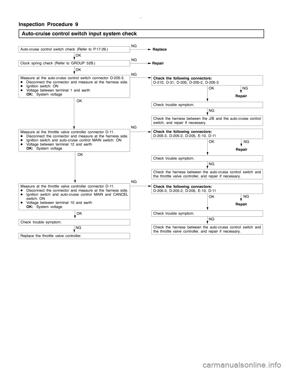
Inspection Procedure 9
Auto-cruise control switch input system check
NG
Check the harness between the auto-cruise control switch and
the throttle valve controller, and repair if necessary.
OK
NG
Repair
OK
Check trouble symptom. NG
OK
Auto-cruise control switch check (Refer to P.17-29.)NG
Replace
NG OKClock spring check (Refer to GROUP 52B.)
Repair
OK
NG
Repair
NG
OK
Check trouble symptom.
NG
Check the harness between the J/B and the auto-cruise control
switch, and repair if necessary.
Check the following connectors:
D-210, D-31, D-205, D-205-2, D-205-3
OK
Check trouble symptom.
NG
Repair
NG
Replace the throttle valve controller.NG
Measure at the throttle valve controller connector D-11.
DDisconnect the connector and measure at the harness side.
DIgnition switch and auto-cruise control MAIN switch: ON
DVoltage between terminal 12 and earth
OK:System voltage
Measure at the auto-cruise control switch connector D-205-3.
DDisconnect the connector and measure at the harness side.
DIgnition switch: ON
DVoltage between terminal 1 and earth
OK:System voltage
NG
Check the harness between the auto-cruise control switch and
the throttle valve controller, and repair if necessary.
OK
Check trouble symptom.
Check the following connectors:
D-205-3, D-205-2, D-205, E-10, D-11
Measure at the throttle valve controller connector D-11.
DDisconnect the connector and measure at the harness side.
DIgnition switch and auto-cruise control MAIN and CANCEL
switch: ON
DVoltage between terminal 10 and earth
OK:System voltageCheck the following connectors:
D-205-3, D-205-2, D-205, E-10, D-11
www.WorkshopManuals.co.uk
Purchased from www.WorkshopManuals.co.uk
Page 826 of 1839
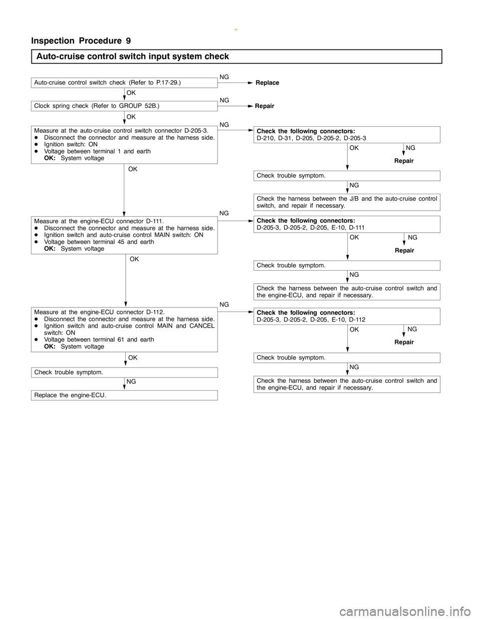
ENGINE AND EMISSION CONTROL -Auto-cruise Control System17-24
Inspection Procedure 9
Auto-cruise control switch input system check
NG
Check the harness between the auto-cruise control switch and
the engine-ECU, and repair if necessary.
OK
NG
Repair
OK
Check trouble symptom. NG
OK
Auto-cruise control switch check (Refer to P.17-29.)NG
Replace
NG OKClock spring check (Refer to GROUP 52B.)
Repair
OK
NG
Repair
NG
OK
Check trouble symptom.
NG
Check the harness between the J/B and the auto-cruise control
switch, and repair if necessary.
Check the following connectors:
D-210, D-31, D-205, D-205-2, D-205-3
OK
Check trouble symptom.
NG
Repair
NG
Replace the engine-ECU.NG
Measure at the engine-ECU connector D-111.
DDisconnect the connector and measure at the harness side.
DIgnition switch and auto-cruise control MAIN switch: ON
DVoltage between terminal 45 and earth
OK:System voltage
Measure at the auto-cruise control switch connector D-205-3.
DDisconnect the connector and measure at the harness side.
DIgnition switch: ON
DVoltage between terminal 1 and earth
OK:System voltage
NG
Check the harness between the auto-cruise control switch and
the engine-ECU, and repair if necessary.
OK
Check trouble symptom.
Check the following connectors:
D-205-3, D-205-2, D-205, E-10, D-111
Measure at the engine-ECU connector D-112.
DDisconnect the connector and measure at the harness side.
DIgnition switch and auto-cruise control MAIN and CANCEL
switch: ON
DVoltage between terminal 61 and earth
OK:System voltageCheck the following connectors:
D-205-3, D-205-2, D-205, E-10, D-112
www.WorkshopManuals.co.uk
Purchased from www.WorkshopManuals.co.uk