coolant temperature MITSUBISHI SPYDER 1990 Service Repair Manual
[x] Cancel search | Manufacturer: MITSUBISHI, Model Year: 1990, Model line: SPYDER, Model: MITSUBISHI SPYDER 1990Pages: 2103, PDF Size: 68.98 MB
Page 628 of 2103
ENGINE (TURBO)
AND ENGINE> Troubleshooting
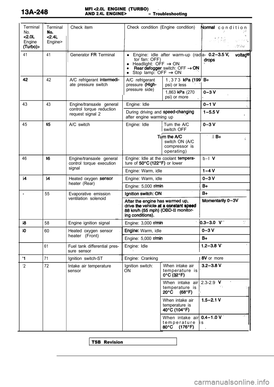
TerminalCheck itemCheck condition (Engine condition) c o n d i t i o n
No.
Engine>
Terminal
No.
Engine
41 41Generator Terminall Engine: idle after warm-up (radia-
tor fan: OFF)
l Headlight: OFF ONl switch: OFF l Stop lamp: OFF ON
A/C refrigerant A/C refrigerant1 , 3 7 3
ate pressure switch
pressurepsi) or less
pressure side)
1,863 (270
psi) or more
Engine/transaxle general
control torque reduction
request signal 2 Engine: Idle
During driving and
after engine warming up
Engine: Idle
Turn the A/C
,
switch OFF
switch ON (A/C
compressor is
operating)
Engine: Idle at the coolant b - l
ture of or lower
Engine: Warm, idle
Engine: Warm, idle
Engine: 5,000
the at a constant speed
Engine: 3,000
Warm, idle
Engine: 5,000
Engine: Idle
I
Engine: CrankingIor more
Ignition switch:
ON When intake air
t e m p e r a t u r e i s
When intake air 2.3-2.9
t e m p e r a t u r e i s
When intake air
temperature is
When intake air
t e m p e r a t u r e i s
.
42
4343
A/C switch45
46Engine/transaxle general
control torque execution
signal
Heated oxygen
heater (Rear)
55Evaporative emission
ventilation solenoid
58Engine ignition signal
Heated oxygen sensor
heater (Front)
60
61Fuel tank differential pres-
sure sensor
71Ignition switch-ST
Intake air temperature
sensor
‘272
TSB Revision
Page 632 of 2103
ENGINE (TURBO)
AND ENGINE> Troubleshooting
Terminal’ No.
6 - 1 2
9 - 1 2 11-12
ground
ground
54-12
55-12
72-92
17-92
-Body
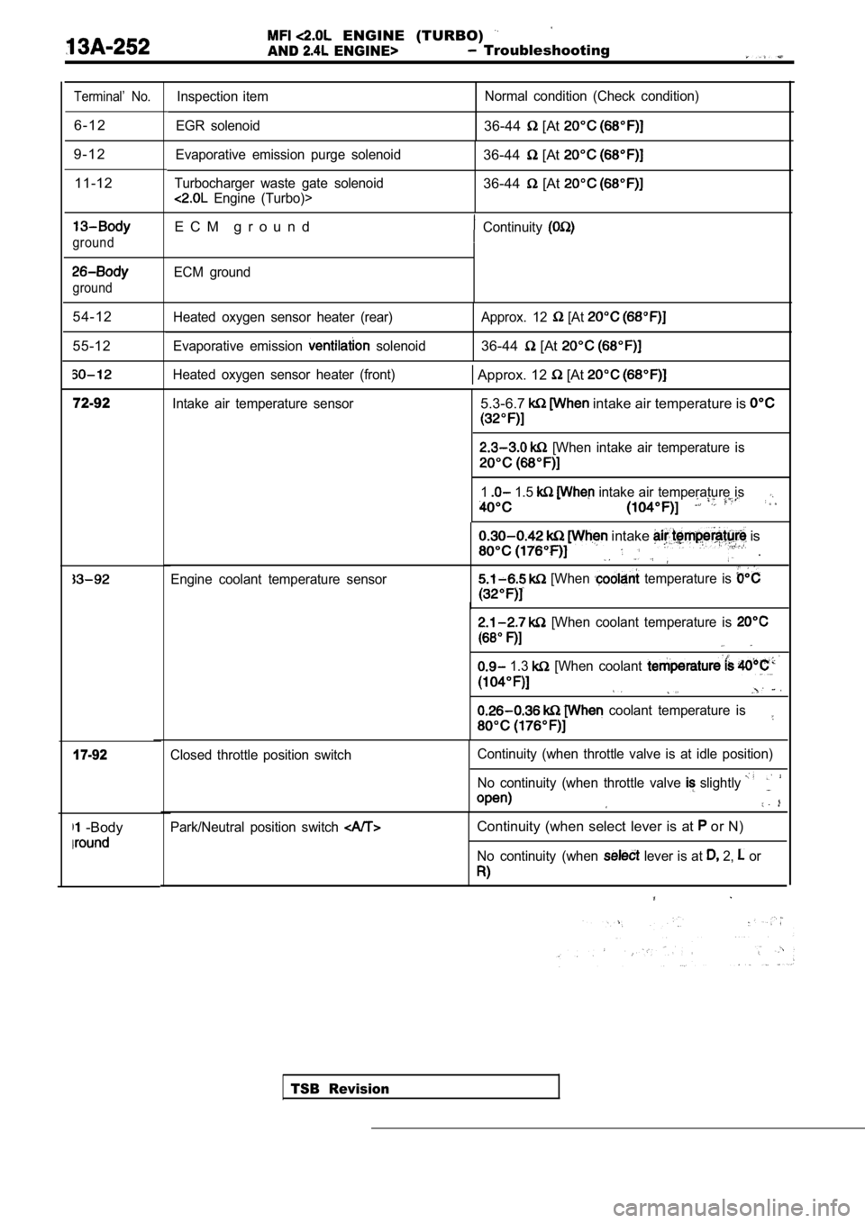
Inspection item
EGR solenoid Normal condition (Check condition)
36-44 [At
Evaporative emission purge solenoid
Turbocharger waste gate solenoid
Engine (Turbo)>
36-44 [At
36-44 [At
E C M g r o u n dContinuity
ECM ground
Heated oxygen sensor heater (rear)
Evaporative emission
solenoid Approx. 12
[At
36-44 [At
Heated oxygen sensor heater (front) Approx. 12 [At
Intake air temperature sensor5.3-6.7 intake air temperature is
[When intake air temperature is
1 1.5 intake air temperature is
Engine coolant temperature sensor
intake is
.
[When temperature is
[When coolant temperature is
1.3 [When coolant
coolant temperature is
TSB Revision
Closed throttle position switch
Continuity (when throttle valve is at idle position
)
No continuity (when throttle valve
slightly
Park/Neutral position switch Continuity (when select lever is at or N)
No continuity (when lever is at 2, or
Page 638 of 2103
Analyzer
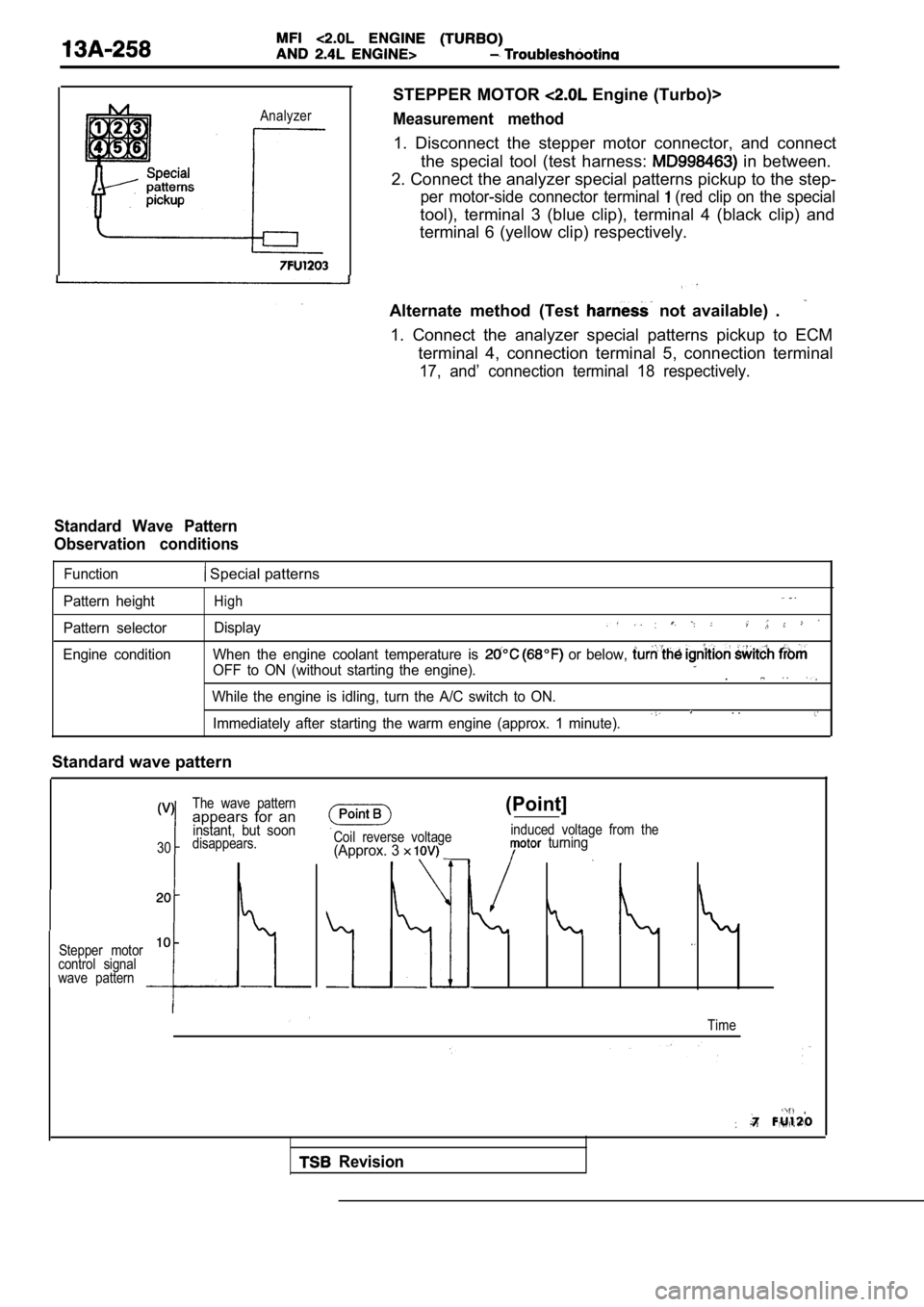
STEPPER MOTOR Engine (Turbo)>
Measurement method
1. Disconnect the stepper motor connector, and connect
the special tool (test harness:
in between.
2. Connect the analyzer special patterns pickup to the step-
per motor-side connector terminal (red clip on the special
tool), terminal 3 (blue clip), terminal 4 (black clip) and
terminal 6 (yellow clip) respectively.
Alternate method (Test
not available) .
1. Connect the analyzer special patterns pickup to ECM
terminal 4, connection terminal 5, connection termi nal
17, and’ connection terminal 18 respectively.
Standard Wave Pattern
Observation conditions
Function Special patterns
Pattern height
Pattern selector
Engine conditionHigh
Display
When the engine coolant temperature is or below,
OFF to ON (without starting the engine)..
While the engine is idling, turn the A/C switch to ON.. .Immediately after starting the warm engine (approx. 1 minute).
Standard wave pattern
The wave patternappears for aninstant, but soon
30disappears.
Stepper motor
10
control signal
wave pattern
Coil reverse voltage(Approx. 3
(Point]
induced voltage from the turning
Time
Revision
Page 646 of 2103
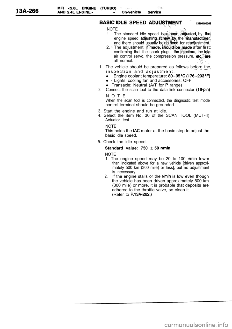
SPEED
NOTE
1.The standard idle speed by,
engine speed the
and there should usually for readjustment.
2. The adjustment, after first:
confirming that the spark plugs; the
air control servo, the compression pressure,
all normal.
1.. The vehicle should be prepared as follows before the
i n s p e c t i o n a n d a d j u s t m e n t .
lEngine coolant temperature:
l Lights, cooling fan and accessories: OFF
‘2.
l Transaxle: Neutral (A/T for range)
Connect the scan tool to the data link connector
N O T E
When the scan tool is connected, the diagnostic tes t mode
control terminal should be grounded.
3. Start the engine and run at idle.
4. Select the item No. 30 of the SCAN TOOL (MUT-II)
Actuator test.
NOTE
This holds the motor at the basic step to adjust the
basic idle speed.
5. Check the idle speed. Standard value: 750
50
NOTE
1. The engine speed may be 20 to 100 lower
than indicated above for a new vehicle [driven appr oxi-
mately 500 km (300 mile) or less], but no adjustment
is necessary.
2.If the engine stalls or the is low even though
the vehicle has been driven approximately 500 km (300 mile) or more, it is probable that deposits ar e
adhered to the throttle valve, so clean it. (Refer to
Page 652 of 2103
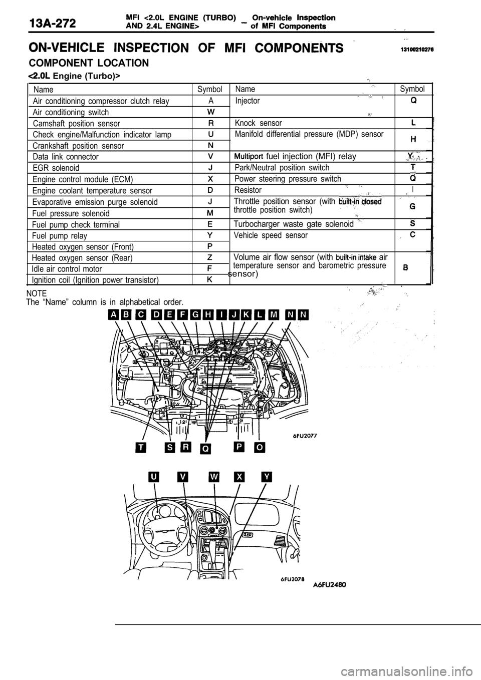
COMPONENT LOCATION
Engine (Turbo)>
Name
Air conditioning compressor clutch relay
Air conditioning switch Camshaft position sensor
Check engine/Malfunction indicator lamp
Crankshaft position sensor Data link connector
EGR solenoid
Engine control module (ECM)
Engine coolant temperature sensor
Evaporative emission purge solenoid
Fuel pressure solenoid
Fuel pump check terminal
Fuel pump relay
Heated oxygen sensor (Front)
Heated oxygen sensor (Rear)
Idle air control motor Ignition coil (Ignition power transistor)
NOTESymbol NameSymbol
A Injector
Knock sensor
Manifold differential pressure (MDP) sensor
fuel injection (MFI) relay
Park/Neutral position switch
Power steering pressure switch
ResistorI.
Throttle position sensor (with
throttle position switch)
Turbocharger waste gate solenoid
Vehicle speed sensor
Volume air flow sensor (with air
temperature sensor and barometric pressure
sensor)
.
The “Name” column is in alphabetical order.
Page 656 of 2103
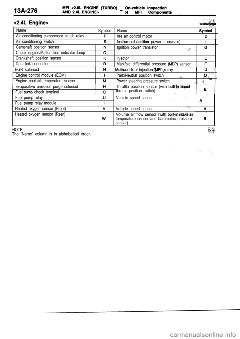
Name
Air conditioning compressor clutch relay
Air conditioning switchSymbol Name
air control motor
coil power transistor)
Camshaft position sensor
Check engine/Malfunction indicator lamp
Crankshaft position sensor
Data link connectorIgnition power transistor
injector
Manifold differential pressure sensor
EGR solenoid fuel relavI I
Engine control module (ECM)
Engine coolant temperature sensorPark/Neutral position switch
Power steering pressure switch
Evaporative emission purge solenoid
Fuel
check terminal
Throttle position sensor (with
throttle position switch)
Fuel pump relay
Fuel pump relay module
Heated oxygen sensor (Front)
Heated oxygen sensor (Rear)Vehicle speed sensor.
Vehicle speed sensor
Volume air flow sensor (with
temperature sensor and barometric pressure
sensor)
NOTE
The “Name” column is in alphabetical order.
Page 661 of 2103
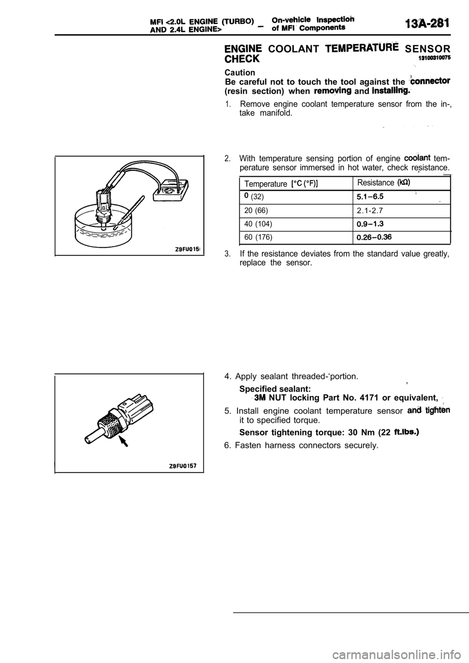
COOLANT SENSOR
Caution
Be careful not to touch the tool against the
(resin section) when and
1.Remove engine coolant temperature sensor from the in-,
take manifold.
2.With temperature sensing portion of engine tem-
perature sensor immersed in hot water, check resist ance.
,
Temperature
(32)
20 (66)
40 (104)
60 (176)
Resistance
2.1-2.7
3.If the resistance deviates from the standard value greatly,
replace the sensor.
4. Apply sealant threaded-‘portion. ,
Specified sealant:
NUT locking Part No. 4171 or equivalent,
5. Install engine coolant temperature sensor
it to specified torque.
Sensor tightening torque: 30 Nm (22
6. Fasten harness connectors securely.
Page 665 of 2103
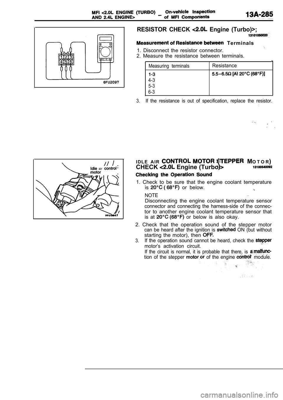
RESISTOR CHECK Engine (Turbo)>;
T e r m i n a l s
1. Disconnect the resistor connector.
2. Measure the resistance between terminals.
Measuring terminalsResistance
4-3
5-3
6-3
3.
If the resistance is out of specification, replace the resistor.
ai r
I D L E A I R MO T O R )
CHECK Engine (Turbo
1. Check to be sure that the engine coolant tempera ture
is
or below.
NOTE
Disconnecting the engine coolant temperature sensor
connector and connecting the harness-side of the co nnec-
tor to another engine coolant temperature sensor th at
is at
or below is also okay.
2. Check that the operation sound of the stepper mo tor
can be heard after the ignition is ON (but without
starting the motor), then
3.If the operation sound cannot be heard, check the
motor’s activation circuit.
If the circuit is normal, it is probable that there, is
tion of the stepper of the engine module.
Page 692 of 2103
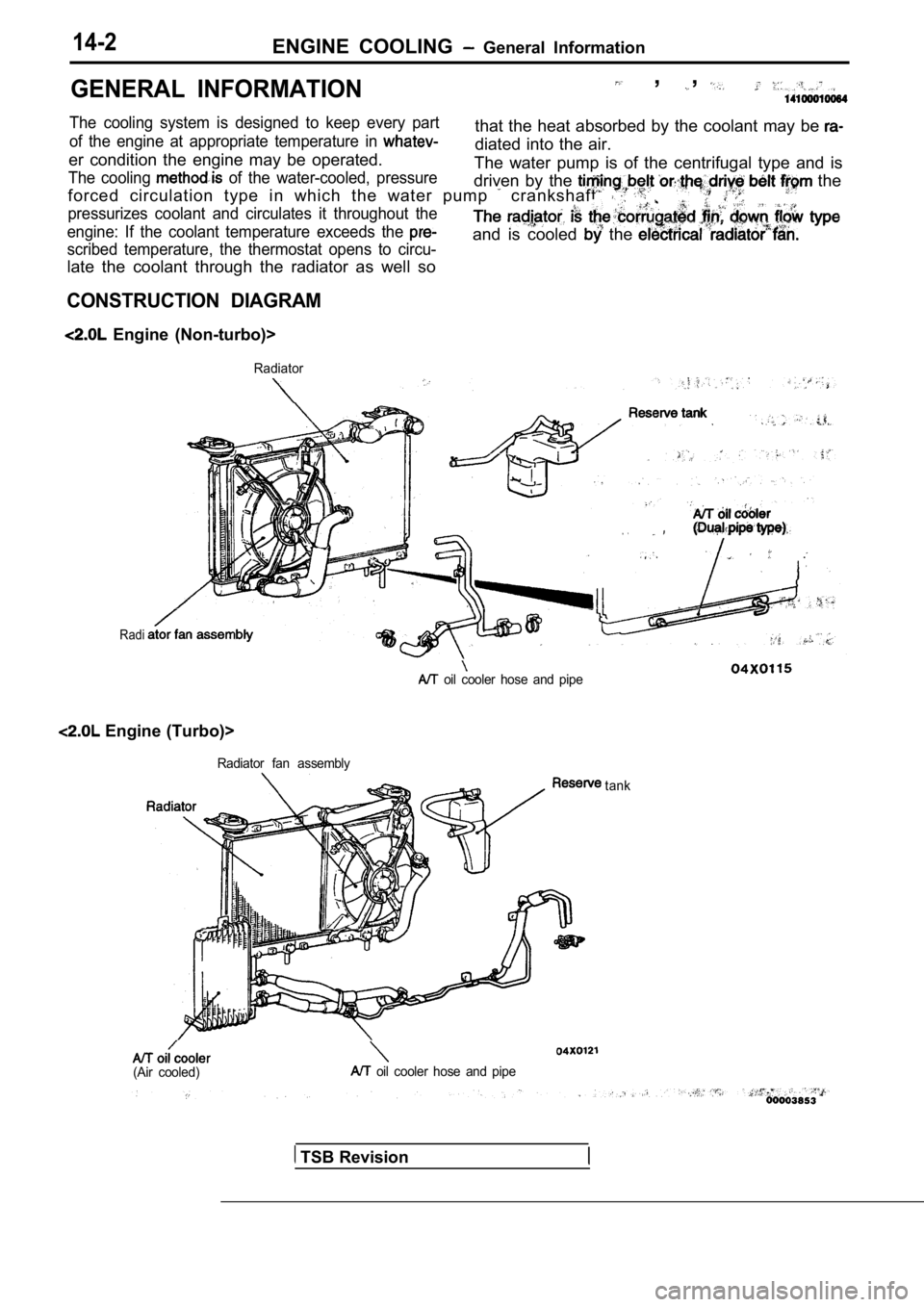
14-2ENGINE COOLING General Information
GENERAL INFORMATION , ,
The cooling system is designed to keep every partthat the heat absorbed by the coolant may be of the engine at appropriate temperature in diated into the air.
er condition the engine may be operated.
The cooling of the water-cooled, pressureThe water pump is of the centrifugal type and is
driven by the
the
forced circulation type in which the water pump crankshaft. .
pressurizes coolant and circulates it throughout th e
engine: If the coolant temperature exceeds the
scribed temperature, the thermostat opens to circu-
late the coolant through the radiator as well so
and is cooled the
CONSTRUCTION DIAGRAM
Engine (Non-turbo)>
Radiator
Radi
.
oil cooler hose and pipe
Engine (Turbo)>
Radiator fan assembly
(Air cooled) oil cooler hose and pipetank
TSB Revision
Page 693 of 2103
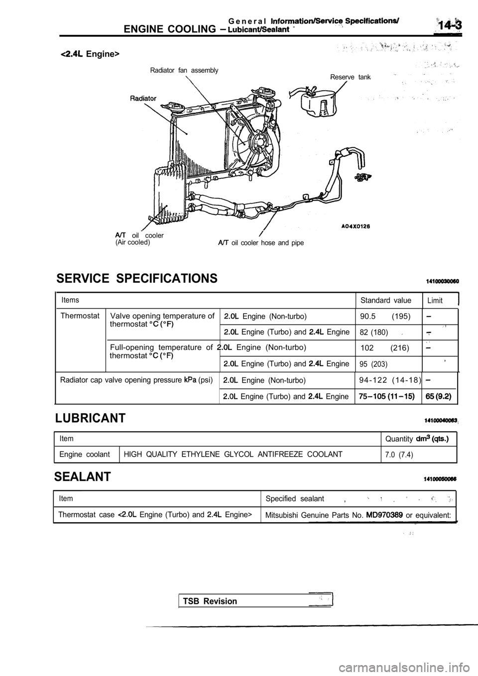
G e n e r a l
ENGINE COOLING
Engine>
Radiator fan assemblyReserve tank
(Airoilcooler
cooled) oil cooler hose and pipe
SERVICE SPECIFICATIONS
ItemsStandard valueLimit
ThermostatValve opening temperature of Engine (Non-turbo)90.5 (195) thermostat Engine (Turbo) and Engine 82 (180)
Full-opening temperature of Engine (Non-turbo)
102 (216)
thermostat
Engine (Turbo) and Engine95 (203),
Radiator cap valve opening pressure (psi) Engine (Non-turbo)9 4 - 1 2 2 ( 1 4 - 1 8 )
Engine (Turbo) and Engine
LUBRICANT
ItemQuantity
Engine coolant HIGH QUALITY ETHYLENE GLYCOL ANTIFREE ZE COOLANT7.0 (7.4)
SEALANT
ItemSpecified sealant,
Thermostat case Engine (Turbo) and Engine>
Mitsubishi Genuine Parts No. or equivalent:
TSB Revision