coolant temperature MITSUBISHI SPYDER 1990 Service Repair Manual
[x] Cancel search | Manufacturer: MITSUBISHI, Model Year: 1990, Model line: SPYDER, Model: MITSUBISHI SPYDER 1990Pages: 2103, PDF Size: 68.98 MB
Page 812 of 2103
(Turbo) and Engine>
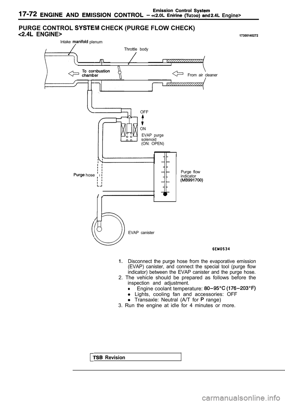
PURGE CONTROL CHECK (PURGE FLOW CHECK)
ENGINE>17300140272
IntakeplenumThrottle body
From air cleaner
OFF
ON EVAP purge
solenoid
(ON: OPEN)
hose IPurge flow
indicator
Revision
EVAP canister
Disconnect the purge hose from the evaporative emis sion
(EVAP) canister, and connect the special tool (purg e flow
indicator) between the EVAP canister and the purge hose.
2. The vehicle should be prepared as follows before the
inspection and adjustment.
lEngine coolant temperature:
l Lights, cooling fan and accessories: OFF
l Transaxle: Neutral (A/T for
range)
3. Run the engine at idle for 4 minutes or more.
Page 816 of 2103
AND C O N T R O L (Turbo) and Engine>
Valve
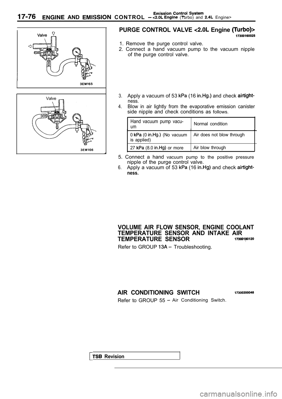
PURGE CONTROL VALVE Engine
1. Remove the purge control valve.
2. Connect a hand vacuum pump to the vacuum nipple of the purge control valve.
3.Apply a vacuum of 53 (16 and check
ness.
4.Blow in air lightly from the evaporative emission c anister
side nipple and check conditions as follows.
Hand vacuum pump vacu-
umNormal condition
0 (0 (No vacuumAir does not blow through
is applied)
27
(8.0 or more Air blow through
5. Connect a hand
vacuum pump to the positive pressure
nipple of the purge control valve.
6.Apply a vacuum of 53 (16 and check
ness.
Revision
VOLUME AIR FLOW SENSOR, ENGINE COOLANT
TEMPERATURE SENSOR AND INTAKE AIR
TEMPERATURE SENSOR
Refer to GROUP Troubleshooting.
AIR CONDITIONING SWITCH
Refer to GROUP 55 Air Conditioning Switch.
Page 820 of 2103
(Turbo) and Engine>
EXHAUST GAS RECIRCULATION
GENERAL INFORMATION
The exhaust gas recirculation (EG system lowers
the nitrogen oxide
emission level. When the
air/fuel mixture combustion temperature is high,
a large quantity of nitrogen oxides is gener-
ated in the combustion Therefore, this
system recirculates part of emission gas from the
exhaust port of the cylinder head to the combustion
OPERATION
When the engine coolant is low, when
the engine is at idle or when a wide open throttle
operation is performed, the EGR valve is kept
closed, achieving no EGR.
The manifold differential pressure sensor is locate d
in the intake manifold plenum. This sensor detects
variations in the manifold pressure when
the EGR solenoid is momentarily operated. If the
manifold negative pressure the EGR sys-
tem is normal.
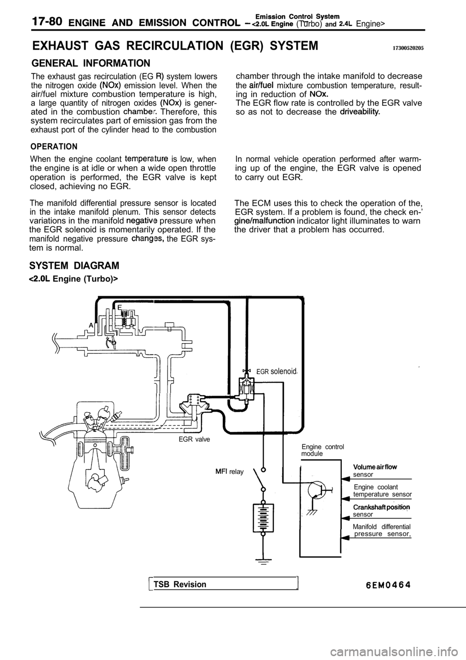
SYSTEM DIAGRAM
Engine (Turbo)>
(EGR) SYSTEM17300520205
chamber through the intake manifold to decrease
the mixture combustion temperature, result-
ing in reduction of
The EGR flow rate is controlled by the EGR valve
so as not to decrease the
In normal vehicle operation performed after warm-
ing up of the engine, the EGR valve is opened
to carry out EGR.
The ECM uses this to check the operation of the, EGR system. If a problem is found, the check en-’
indicator light illuminates to warn
the driver that a problem has occurred.
EGR valve
relay
EGRsolenoid
Engine control
module
Isensor
Engine coolant
temperature sensor
sensor
Manifold differential
TSB Revision
pressure sensor,
Page 823 of 2103
Emission Control
ENGINE AND EMISSION CONTROL Engine
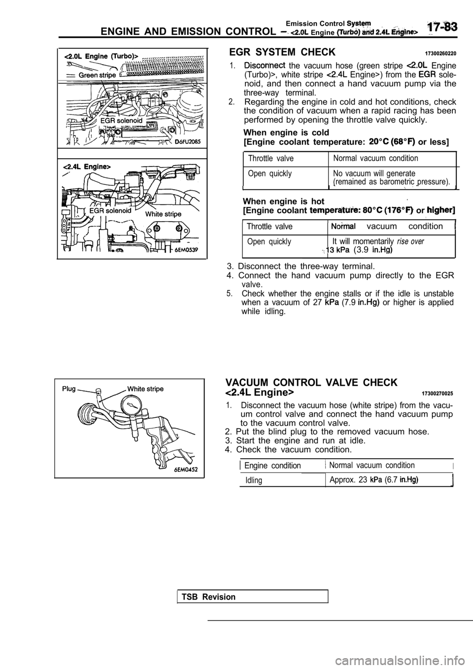
EGR SYSTEM CHECK17300260220
1. the vacuum hose (green stripe Engine
(Turbo)>, white stripe
Engine>) from the sole-
noid, and then connect a hand vacuum pump via the
three-way terminal.
2.Regarding the engine in cold and hot conditions, ch eck
the condition of vacuum when a rapid racing has bee n
performed by opening the throttle valve quickly.
When engine is cold [Engine coolant temperature:
or less]
Throttle valve
Open quickly Normal vacuum condition
No vacuum will generate
(remained as barometric pressure).
I
When engine is hot
[Engine coolant or
Throttle valve vacuum condition
Open quicklyIt will momentarily rise over
(3.9
3. Disconnect the three-way terminal.
4. Connect the hand vacuum pump directly to the EGR
valve.
5.Check whether the engine stalls or if the idle is u nstable
when a vacuum of 27
(7.9 or higher is applied
while idling.
VACUUM CONTROL VALVE CHECK
Engine>17300270025
1.Disconnect the vacuum hose (white stripe) from the vacu-
um control valve and connect the hand vacuum pump
to the vacuum control valve.
2. Put the blind plug to the removed vacuum hose.
3. Start the engine and run at idle.
4. Check the vacuum condition.
Engine condition Normal vacuum conditionI
IdlingApprox. 23 (6.7
TSB Revision
Page 1072 of 2103
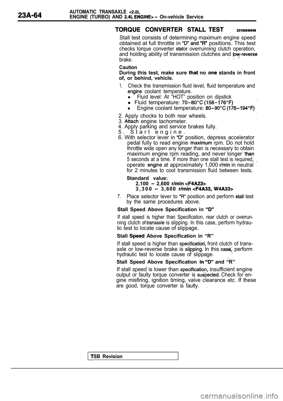
AUTOMATIC TRANSAXLE
ENGINE (TURBO) AND On-vehicle Service
Stall test consists of determining maximum engine speed
obtained at full throttle in positions. This test
checks torque converter overrunning clutch operation,
and holding ability of transmission clutches and
brake.
Caution
During this test, make sure no stands in front
of, or behind, vehicle.
1.Check the transmission fluid level, fluid temperatu re and
coolant temperature.
lFluid level: At “HOT” position on dipstick
l Fluid temperature:
lEngine coolant temperature:
2. Apply chocks to both rear wheels.
3.
engine tachometer.
4. Apply parking and service brakes fully.
5 . S t a r t e n g i n e .
6. With selector lever in position, depress accelerator
pedal fully to read engine
rpm. Do not hold
throttle wide open any longer than is necessary to obtain
maximum engine rpm reading, and never longer
5 seconds at a time. If more than one stall test is required,
operate at approximately 1,000 in neutral
for 2 minutes to cool transmission fluid between te sts.
Standard value:
TSB Revision
2,100 2,600
3 , 3 0 0 3 , 6 0 0
7.Place selector lever to position and perform test
by the same procedures above.
Stall Speed Above Specification in
If stall speed is higher than Specification, rear c lutch or overrun-
ning clutch is slipping. In this case, perform hydrau-
lic test to locate cause of slippage.
Stall Above Specification in “R”
If stall speed is higher than front clutch of trans-
axle or low-reverse brake is In this perform
hydraulic test to locate cause of slippage.
Stall Speed Above Specification and “R”
If stall speed is lower than insufficient engine
output or faulty torque converter is Check for en-
gine misfiring, ignition timing, valve clearance etc. If these
are good, torque converter is faulty..
Page 1163 of 2103
AUTOMATIC TRANSAXLE
ENGINE (NON-TURBO)>
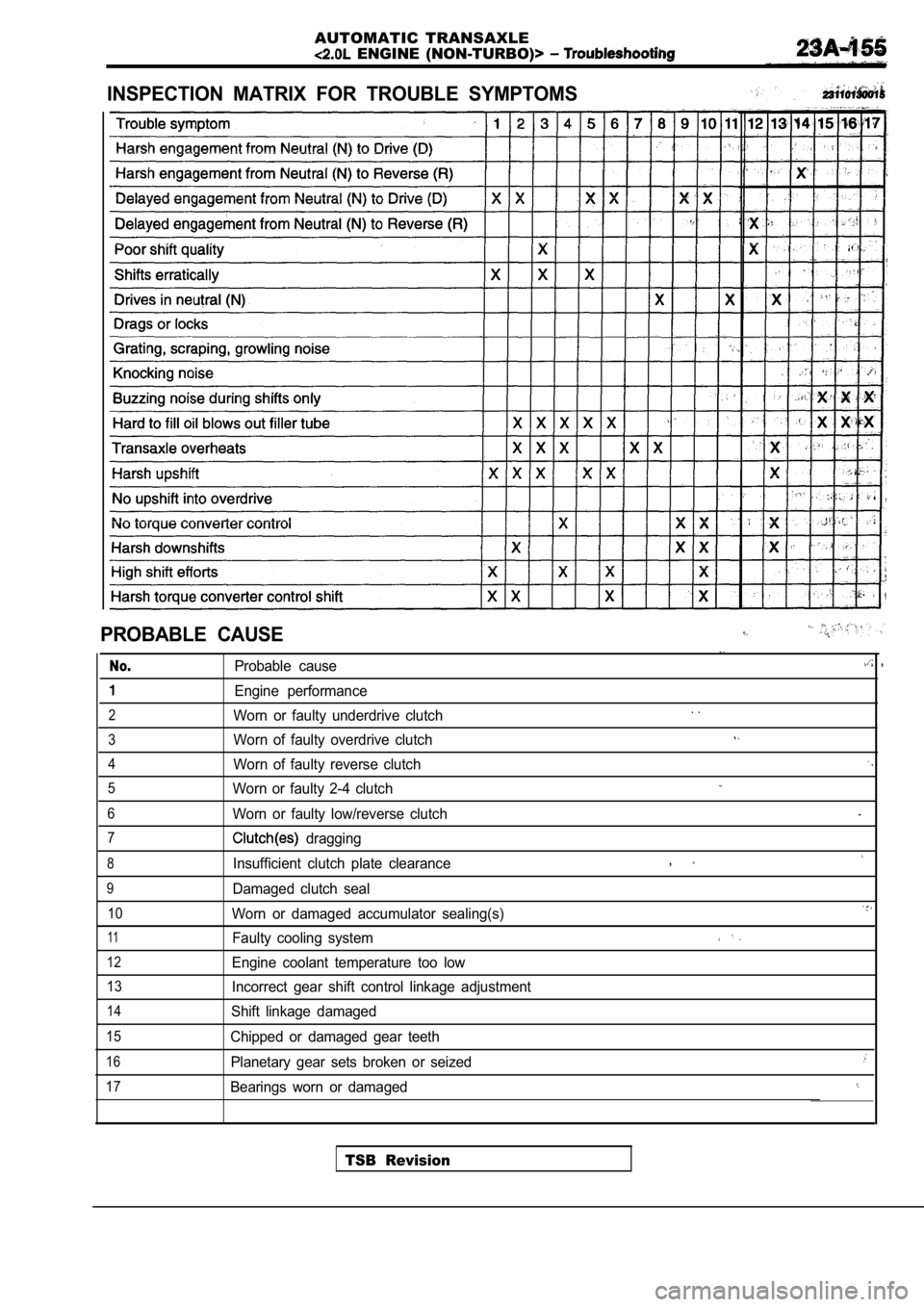
INSPECTION MATRIX FOR TROUBLE SYMPTOMS
PROBABLE CAUSE
No.Probable cause
Engine performance
2Worn or faulty underdrive clutch
3Worn of faulty overdrive clutch
4Worn of faulty reverse clutch
5Worn or faulty 2-4 clutch
6Worn or faulty low/reverse clutch
7 dragging
8Insufficient clutch plate clearance
9Damaged clutch seal
10Worn or damaged accumulator sealing(s)
11Faulty cooling system
12Engine coolant temperature too low
13Incorrect gear shift control linkage adjustment
14Shift linkage damaged
15Chipped or damaged gear teeth
16Planetary gear sets broken or seized
17Bearings worn or damaged
,
. .
,
TSB Revision
Page 1171 of 2103

AUTOMATIC TRANSAXLE
ENGINE (NON-TURBO)>: On-vehicle _ _
AUTOMATIC
COMPONENT CHECK
SPEED SENSOR
(1) Disconnect the input speed sensor connector.
(2) Measure the resistance
the input speed
side connector terminals 1 and 2.
Standard value:,
(3) If the resistance is outside the standard value , replace
the input speed sensor.
OUTPUT SPEED SENSOR CHECK
(1) Disconnect the output speed sensor connector.
(2) Measure the resistance between the input speed
side connector terminals 1 2.
Standard value:
(3) If the resistance is outside the standard value , replace
the output speed sensor.
TRANSAXLE RANGE SENSOR CONTINUITY CHECK
Refer to
OVERDRIVE SWITCH CONTINUITY CHECK
Refer to
POSITION SENSOR (TPS) CHECK
Refer to GROUP On-vehicle Inspection of Compo-
nents.
ENGINE COOLANT TEMPERATURE SENSOR CHECK
.
Refer to GROUP On-vehicle Inspection of
nents.
CRANKSHAFT CHECK
Refer to GROUP Troubleshooting.
ABSOLUTE PRESSURE SENSOR
Refer to On-vehicle Inspection of
nents.
Revision
Page 2043 of 2103
HEATER, AIR
AND VENTILATION General Information
GENERAL INFORMATION
The heater system uses a two-way-flow full-air-mixThe A/C system is basically the same as the
system that features high performance and lowtional system, but a new refrigerant system
operating noise, and includes an independent facebeen adopted as a response to
air blowing function and a air bypass function.use of chlorofluorocarbons. ,
Specifications
Heater unit type Two-way-flow full-air-mix system
Heater
controlassembly Dial and lever type
Compressor model
Engine (Turbo) and Scroll type
Engine>
Engine (Non-turbo)>Inclined-plate type
Dual pressure switch (psi)High-pressure switch OFF: 3,140 ON: 2,550 (370)
Low-pressureswitchOFF: 200 ON: 220 (32)
Refrigerant and quantity
(oz.) Approx. 700 740
OPERATION
Condenser fan and radiator fan control
lFor the operation of each fan, refer to COOLING
SYSTEM TROUBLESHOOTING.
Compressor control
lWhen the air conditioning switch is pushed in (A/C switch: ON) or the air outlet changeover
control knob is moved to the DEF or
position (defroster switch: ON), the air
conditioning system operates and compressor
control starts.
l The fin sensor, which senses the
temperature. of the air flowing out of the
evaporator, is deactivated with. temperature
3.2%
or below.
Here, the engine coolant ‘temperature sensor
senses the temperature of coolant,
it is turned off at or higher
peratures.
lThe dual pressure switch turns OFF when
refrigerant pressure becomes high
or low, thus the compressor circuit.
(See Table below.)
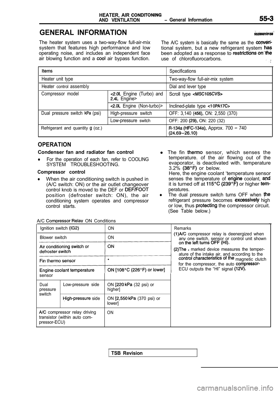
A/C ON Conditions
Ignition switch
Blower switch
ON
ON Remarks
compressor relay is deenergized when
anv one switch, sensor or control unit shown
l marked device measures the temper-
ature of the intake air, and according to the
magnetic clutch
for the compressor, the auto
ECU outputs the “HI” signal
sensor
DualLow-pressure side ON (32 psi) or
pressure
higher]
switch side ON (370 psi) or
lower]
compressor relay driving
transistor (within auto com-
pressor-ECU)ON
TSB Revision
Page 2057 of 2103
HEATER, AIR
AND VENTILATION On-vehicle Service
IDLE-UP OPERATION CHECK
1,Before inspection and adjustment, set the f&w-
ing condition:
lEngine coolant temperature:
lLights, electric cooling fan and accessories: Set t o
OFF
lTransmission: Neutral (N or for vehicles with
l Steering wheel:
2. Check whether or not the idling speed is the sta ndard
value.
Blower relay
Standard value:
100
Engine (Turbo) and Engine>
100 Engine (Non-turbo)>
3. When the
is running after turning the A/C switch
to ON, and the blower switch to the MH or HI positi on,
check to be sure that the idle speed is at the stan dard
value.
Standard value: (in Neutral)
NOTE
Idle speed is controlled by the system and is not
adjustable. If, idle speed is not within specifications, check
the system.
Engine (Non-turbo)>: Refer to GROUP On-
vehicle Service.)
Engine (Turbo)>: Refer to GROUP On-vehicle
Service.)
Engine>: Refer to GROUP On-vehicle Ser-
vice.)
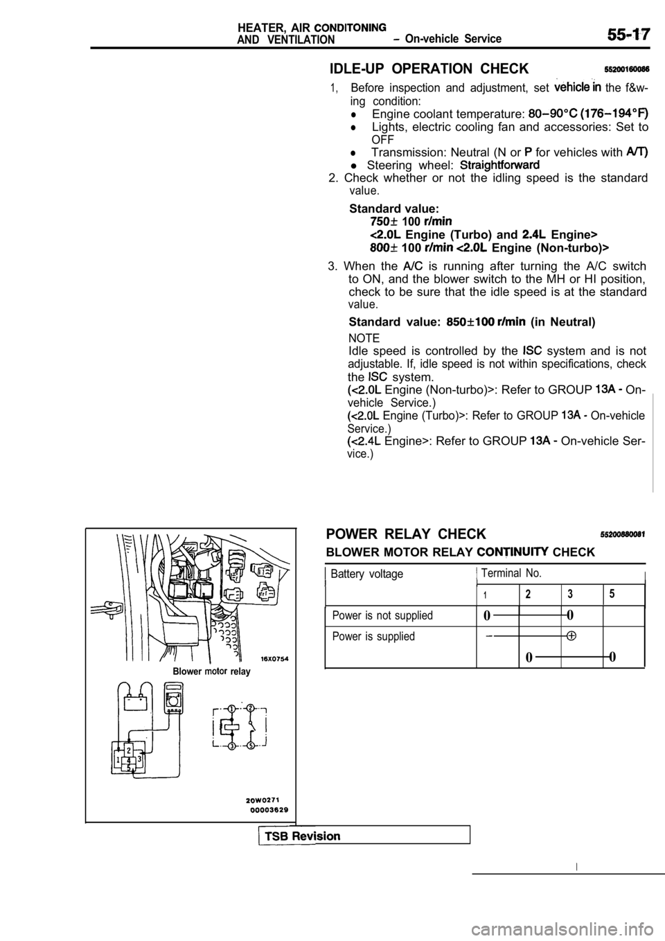
POWER RELAY CHECK
BLOWER MOTOR RELAY CHECK
Battery voltage Terminal No.III
1235
Power is not supplied
Power is supplied0 0
0 0
Page 2096 of 2103
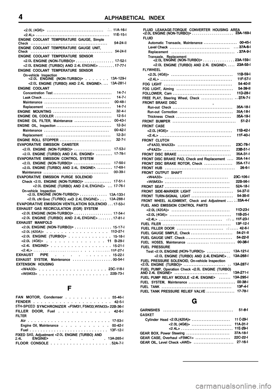
ALPHABETICAL INDEX
. . . . . . . . . . . . . . . . . . . . . . . . . . . . . . . . . ..
. . . . . . . . . . . . . . . . . . . . . . . . . . . . . . . . . . . . . . . . . . . .
ENGINE COOLANT TEMPERATURE GAUGE, SimpleCheck. . . . . . . . . . . . . . . . . . . . . . . . . . . . . . . . . . . . . . . . . . . . . .
ENGINE COOLANT TEMPERATURE GAUGE UNIT,Check. . . . . . . . . . . . . . . . . . . . . . . . . .
. . . . . . . . . . . . . . . . . . . .
ENGINE COOLANT TEMPERATURE SENSOR
ENGINE (NON-TURBO)> . . . . . . . . . . . . . . . . . .
ENGINE (TURBO) AND . . . . . . .
ENGINE COOLANT TEMPERATURE SENSOR
On-vehicle Inspection ENGINE (NON-TURBO)> . . . . . . .
ENGINE (TURBO) AND ENGINE>.. . .
ENGINE COOLANTConcentration Test. . . . . . . . . . . . . . . . . . . . . . . . . . . . . . . . . . .
. . . . . . . . . . . . . . . . . . . . . . . . . . . . . . . . . . . . . . . . .
Maintenance. . . . . . . . . . . . . . . . . . . . . . . . . . . . . . . . . . . . . . .
Replacement. . . . . . . . . . . . . . . . . . . . . . . . . . . . . . . . . . . . . . .
ENGINE MOUNTING. . . . . . . . . . . . . . . . . . . . . . . . . . . . . . . . . . .
ENGINE OIL COOLER. . . . . . . . . . . . . . . . . . . . . . . . . . . . . . . . . .
ENGINE OIL FILTER, Maintenance. . . . . . . . . . . . . . . . . . . . . .
ENGINE OIL, Inspection. . . . . . . . . . . . . . . . . . . . . . . . . . . . . . . . .
Maintenance. . . . . . . . . . . . . . . . . . . . . . . . . . . . . . . . . . . . . . .
Replacement. . . . . . . . . . . . . . . . . . . . . . . . . . . . . . . . . . . . . . .
ENGINE ROLL STOPPER. . . . . . . . . . . . . . . . . . . . . . . . . . . . . . .
EVAPORATIVE EMISSION CANISTER
ENGINE (NON-TURBO)>. . . . . . . . . . . . . . . . . . . . . .
ENGINE (TURBO) AND ENGINE>. . . . . . . . . .
EVAPORATIVE EMISSION CONTROL SYSTEM ENGINE (NON-TURBO)>. . . . . . . . . . . . . . . . . . . . . .
ENGINE (TURBO) AND ENGINE>.. . . . . . . . .
Maintenance. . . . . . . . . . . . . . . . . . . . . . . . . . . . . . . . . . . . . . .
EVAPORATIVE EMISSION PURGE SOLENOID
Check ENGINE (NON-TURBO)>. . . . . . . . . . . . . . . .
ENGINE (TURBO) AND . . .
On-vehicle Inspection ENGINE (NON-TURBO)> . . . . . . . . . . . . .
EN G INE AND . . .
EVAPORATIVE EMISSION VENTILATION SOLENOID . .
EXHAUST GAS RECIRCULATION (EGR) SYSTEM
ENGINE (NON-TURBO)> . . . . . . . . . . . . . . . . . .
ENGINE (TURBO) AND . . . . . . EXHAUST MANIFOLD ENGINE (NON-TURBO)> . . . . . . . . . . . . . . . . . . . . . . . . . . . . . . . . .
ENGINE (TURBO)> . . . . . . . . . . . . .
. . . . . . . . . . . . . . 11
ENGINE> . . . . . . . . . . . . . . . . . .
. . . . EXHAUST PIPE . . . . . . . . . .
EXHAUST SYSTEM, Maintenance. . . . . . . . . . . . . . . . . .
EXTENSION HOUSING
. . . . . . . . . . . . . . . . . . . .
. . . . . . . . . . . . . . . . . . . . .
FAN MOTOR, Condenser . . . . . . . . . . . . FENDER . . . . . . . . . . . . . . . . . . . . .
SYNCHRONIZER
FILLER DOOR, Fuel . . . . . . . . . . . .
FILTER
Air . . . . . . . . . . . . . . . . . . . . . . . . .
Engine Oil, Maintenance. . . . . . . . . . .
Fuel . . . . . . . . . . . . . . . . . . . . . . . . . . . . .
FIXED Adjustment ENGINE (TURBO) AND ENGINE> . . . . .
FLOOR CONSOLE . . . . . . . . . . . . . . . . . .
FLUID LEAKAGE-TORQUE CONVERTER HOUSING AREA ENGINE (NON-TURBO)> . . . . . . . . . . . . . . . . . . . .
FLUID
Automatic Transaxle, Maintenance. . . . . . . . . . . . . . . . . . . .
. . . . . . . . . . . . . . . . . . . . . . . . . . . . . . . . . . . .Replacement. . . . . . . . . . . . . . . . . . . . . . . . . . . . . . . . . . . . . .
Transaxle, Replacement ENGINE (NON-TURBO)> . . . . . . . . . . . . . . .
ENGINE (TURBO) AND ENGINE>.. . . .
FLYWHEEL
. . . . . . . . . . . . . . . . . . . . . . . . . . . . . . . . . . . . .
. . . . . . . . . . . . . . . . . . . . . . . . . . . . . . . . . . . . . . . . . . .
FOG LIGHT. . . . . . . . . . . . . . . . . . . . . . . . . . . . . . . . . . . . . . . . .
FOG LIGHT, Aiming. . . . . . . . . . . . . . . . . . . . . . . . . . . . . . . . . .
FOLLOWER, Cam. . . . . . . . . . . . . . . . . . . . . . . . . . . . . . . . . . .
FREE PLAY, Steering Wheel, Check. . . . . . . . . . . . . . . . . . .
FRONT BRAKE DISC,Run-out Check. . . . . . . . . . . . . . . . . . . . . . . . . . . . . . . . . . . .Run-out Correction. . . . . . . . . . . . . . . . . . . . . . . . . . . . . . . .
Thickness Check. . . . . . . . . . . . . . . . . . . . . . . . . . . . . . . . .
FRONT BUMPER. . . . . . . . . . . . . . . . . . . . . . . . . . . . . . . . . . . . . .
FRONT CASE
. . . . . . . . . . . . . . . . . . . . . . . . . . . . . . . . . . . . .
. . . . . . . . . . . . . . . . . . . . . . . . . . . . . . . . . . . . . . . . . . .
FRONT CLUTCH. . . . . . . . . . . . . . . . . . . . . . . . . . . . . . . .
. . . . . . . . . . . . . . . . . . . . . . . . . . . . . . . . . . . . . . . .FRONT DISC BRAKE. . . . . . . . . . . . . . . . . . . . . . . . . . . . . . . .
FRONT DISC BRAKE PAD, Check and Replacement. . . .
FRONT DISC BRAKE ROTOR, Check. . . . . . . . . . . . . . . . .FRONT HUB. . . . . . . . . . . . . . . . . . . . . . . . . . . . . . . . . . . . . . . . . .
FRONT OUTPUT SHAFT. . . . . . . . . . . . . . . . . . . . . . . . . . . . . . . . . . . . . .. . . . . . . . . . . . . . . . . . . . . . . . . . . . . . . . . . . . . . .
FRONT SEAT. . . . . . . . . . . . . . . . . . . . . . . . . . . . . . . . . . . . . . .
FRONT SIDE-MARKER LIGHT. . . . . . . . . . . . . . . . . . . . . . . .
FRONT TURN-SIGNAL LIGHT. . . . . . . . . . . . . . . . . . . . . . . . .
FRONT WHEEL ALIGNMENT, Check and Adjustment. . . .
FUEL AND EMISSION CONTROL PARTS. . . . . . . . . . . . . . . . . . . . . . . . . . . . . . . . . . .
. . . . . . . . . . . . . . . . . . . . . . . . . . . . . . . . . . . . .. . . . . . . . . . . . . . . . . . . . . . . . . . . . . . . . . . . . . ...
FUEL FILER. . . . . . . . . . . . . . . . . . . . . . . . . . . . . . . . . . . . . . . . .FUEL FILLER DOOR. . . . . . . . . . . . . . . . . . . . . . . . . . . .. . . . .
FUEL GAUGE SIMPLE, Check. . . . . . . . . . . . . . . . . . . . . . . . .
FUEL GAUGE UNIT. Check. . . . . . . . . . . . . . . . . . . . . . . . . . . .
FUEL HOSES, Maintenance. . . . . . . . . . . . .. . . . . . . . . . . . .
FUEL PRESSURETest ENGINE . . . . . . . . . . . . . .
ENGINE (TURBO) AND . .
FUEL PRESSURE SOLENOID, On-vehicle Inspection ENGINE (TURBO)>. . . . . . . . . . . . . . . . . . . . . . . . .
FUEL PUMP, Operation Check ENGINE (TURBO)
AND ENGINE>. . . . . . . . . . . . . . . . . . . . . . . . . . . . . . . .
FUEL PUMP RELAY MODULE ENGINE>. . . . . . .
FUEL SYSTEM, Maintenance. . . . . . . . . . . . . . . . . . . . . . . . . . . .
FUEL TANK. . . . . . . . . . . . . . . . . . . . . . . . . . . . . . . . . . . . . . . . . .FUEL TANK PRESSURE RELIEF VALVE. . . . . . . . . . . . . . . . .
GARNISHES. . . . . . . . . . . . . . . . . . . . . . . . . . . . . . . . . . . . . . . . . .
GASKET
Cylinder Head . . . . . . . . . . . . . . . . . . . . . . .11
. . . . . . . . . . . . . . . . . . . . . . . .. . . . . . . . . . . . . . . . . . . . . . . . . . . . .
GEAR BOX, Power . . . . . . . . . . . . . . . . . . . . . . . . . .
GEAR CASE, Overhaul . . . . . . . . . . . . . . . . . . . . .
GEAR OIL, Level Check . . . . . . . . . . . . . . . . . . . . . . . .